Latest Control and Protection Innovations Applied to the ... - Siemens
Latest Control and Protection Innovations Applied to the ... - Siemens
Latest Control and Protection Innovations Applied to the ... - Siemens

You also want an ePaper? Increase the reach of your titles
YUMPU automatically turns print PDFs into web optimized ePapers that Google loves.
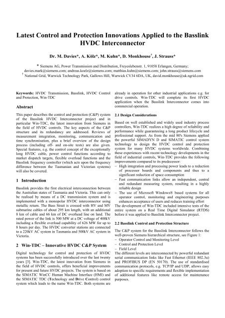
<strong>Latest</strong> <strong>Control</strong> <strong>and</strong> <strong>Protection</strong> <strong>Innovations</strong> <strong>Applied</strong> <strong>to</strong> <strong>the</strong> Basslink<br />
HVDC Interconnec<strong>to</strong>r<br />
Dr. M. Davies*, A. Kölz*, M. Kuhn*, D. Monkhouse † , J. Strauss*<br />
* <strong>Siemens</strong> AG, Power Transmission <strong>and</strong> Distribution, Freyeslebenstr. 1, 91058 Erlangen, Germany;<br />
davies.mark@siemens.com; <strong>and</strong>reas.koelz@siemens.com; matthias.kuhn@siemens.com; john.strauss@siemens.com<br />
† National Grid, Warwick Technology Park, Gallows Hill, Warwick CV34 6DA, UK, david.monkhouse@uk.ngrid.com<br />
Keywords: HVDC Transmission, Basslink, HVDC <strong>Control</strong><br />
<strong>and</strong> <strong>Protection</strong>, Win-TDC<br />
Abstract<br />
This paper describes <strong>the</strong> control <strong>and</strong> protection (C&P) system<br />
of <strong>the</strong> Basslink HVDC Interconnec<strong>to</strong>r project <strong>and</strong> in<br />
particular Win-TDC, <strong>the</strong> latest innovation from <strong>Siemens</strong> in<br />
<strong>the</strong> field of HVDC controls. The key aspects of <strong>the</strong> C&P<br />
structure <strong>and</strong> its redundancy are addressed. Reviews of<br />
measurement integration, moni<strong>to</strong>ring, communication <strong>and</strong><br />
time synchronisation, plus a brief overview of <strong>the</strong> design<br />
process (including off- <strong>and</strong> on-site tests) are also given.<br />
Special features, e.g. <strong>the</strong> control concept of <strong>the</strong> exceptionally<br />
long HVDC cable, power control functions according <strong>to</strong><br />
market dispatch targets, flexible overload functions <strong>and</strong> <strong>the</strong><br />
Basslink frequency controller (which acts upon <strong>the</strong> frequency<br />
difference between <strong>the</strong> Tasmanian <strong>and</strong> Vic<strong>to</strong>rian systems)<br />
will also be covered.<br />
1 Introduction<br />
Basslink provides <strong>the</strong> first electrical interconnection between<br />
<strong>the</strong> Australian states of Tasmania <strong>and</strong> Vic<strong>to</strong>ria. This can only<br />
be realised by means of a DC transmission system <strong>and</strong> is<br />
implemented with a monopolar HVDC interconnec<strong>to</strong>r using<br />
metallic return. The Bass Strait is crossed with HV <strong>and</strong> MV<br />
submarine cables of about 295 km length, with an additional<br />
8 km of cable <strong>and</strong> 66 km of DC overhead line on l<strong>and</strong>. The<br />
rated power of <strong>the</strong> link is 500 MW at a DC voltage of 400kV<br />
including a flexible overload capability of 626 MW for up <strong>to</strong><br />
8 hours per day. The HVDC converter stations are connected<br />
<strong>to</strong> a 220kV AC system in Tasmania <strong>and</strong> 500kV AC system in<br />
Vic<strong>to</strong>ria.<br />
2 Win-TDC – Innovative HVDC C&P System<br />
Digital technology for control <strong>and</strong> protection of HVDC<br />
systems has been successfully introduced over <strong>the</strong> last twenty<br />
years [3]. Win-TDC, <strong>the</strong> latest innovation from <strong>Siemens</strong> in<br />
<strong>the</strong> field of HVDC controls, offers beneficial improvements<br />
for present <strong>and</strong> future HVDC projects. The system is based on<br />
<strong>the</strong> SIMATIC WinCC Human Machine Interface (HMI) <strong>and</strong><br />
<strong>the</strong> SIMATIC TDC (Technology <strong>and</strong> Drive <strong>Control</strong>) control<br />
system which leads <strong>to</strong> <strong>the</strong> name Win-TDC. Both systems are<br />
already in operation for o<strong>the</strong>r industrial applications e.g. for<br />
drive controls. Win-TDC will complete its first HVDC<br />
application when <strong>the</strong> Basslink Interconnec<strong>to</strong>r comes in<strong>to</strong><br />
commercial operation.<br />
2.1 Design Considerations<br />
Based on well established <strong>and</strong> widely used industry process<br />
controllers, Win-TDC realizes a high degree of reliability <strong>and</strong><br />
performance while guaranteeing a long product lifecycle <strong>and</strong><br />
professional support. As from <strong>the</strong> mid 80's <strong>Siemens</strong> applied<br />
<strong>the</strong> powerful SIMADYN D <strong>and</strong> SIMATIC control system<br />
technology <strong>to</strong> design <strong>the</strong> HVDC control <strong>and</strong> protection<br />
system for many HVDC systems worldwide. Combining<br />
<strong>the</strong>se experiences with recent technology developments in <strong>the</strong><br />
field of industrial controls, Win-TDC provides <strong>the</strong> following<br />
improvements compared <strong>to</strong> its predecessor:<br />
− High integration <strong>and</strong> processing power leads <strong>to</strong> a reduction<br />
of processor boards <strong>and</strong> components <strong>and</strong> thus <strong>to</strong> a<br />
significant reduction of space consumption<br />
− Fast communication links allow an independent, central<br />
<strong>and</strong> redundant measuring system, resulting in a highly<br />
reliable design<br />
− The use of Microsoft Windows® based systems for all<br />
opera<strong>to</strong>r control, moni<strong>to</strong>ring <strong>and</strong> engineering purposes<br />
enhances acceptance of users <strong>and</strong> reduces training effort<br />
The development of Win-TDC included intensive tests of <strong>the</strong><br />
entire system on a Real Time Digital Simula<strong>to</strong>r (RTDS)<br />
before it was applied <strong>to</strong> Basslink Interconnec<strong>to</strong>r project.<br />
2.2 Basslink <strong>Control</strong> <strong>and</strong> <strong>Protection</strong> Structure<br />
The C&P system for <strong>the</strong> Basslink Interconnec<strong>to</strong>r follows <strong>the</strong><br />
well-proven <strong>Siemens</strong> hierarchical structure, see Figure 1:<br />
− Opera<strong>to</strong>r <strong>Control</strong> <strong>and</strong> Moni<strong>to</strong>ring Level<br />
− <strong>Control</strong> <strong>and</strong> <strong>Protection</strong> Level<br />
− Field Level<br />
The different levels are interconnected by powerful redundant<br />
serial communication links like Fast E<strong>the</strong>rnet (IEEE 802.3u)<br />
<strong>and</strong> PROFIBUS DP (EN 50170). The use of st<strong>and</strong>ardised<br />
communication pro<strong>to</strong>cols, e.g. TCP/IP <strong>and</strong> UDP, allows easy<br />
adoption <strong>to</strong> specific requirements <strong>and</strong> flexible implementation<br />
of additional features like remote access for maintenance<br />
purposes.
Figure 1: Basslink Win-TDC <strong>Control</strong> <strong>and</strong> <strong>Protection</strong> Structure Showing Redundancies<br />
2.3 Opera<strong>to</strong>r <strong>Control</strong> <strong>and</strong> Moni<strong>to</strong>ring, Communication<br />
The opera<strong>to</strong>r control <strong>and</strong> moni<strong>to</strong>ring level consists of <strong>the</strong><br />
HMI system for control <strong>and</strong> moni<strong>to</strong>ring of <strong>the</strong> plant, <strong>the</strong><br />
remote control interface (RCI) for communication <strong>to</strong> control<br />
centres, <strong>the</strong> transient fault recording system (TFR) <strong>and</strong> <strong>the</strong><br />
inter station communication system.<br />
The fully redundant HMI system for operation of <strong>the</strong> link<br />
from <strong>the</strong> control room at <strong>the</strong> converter stations runs on<br />
st<strong>and</strong>ard Microsoft Windows® personal computers.<br />
Overviews as well as detailed information of subsystems are<br />
presented <strong>to</strong> <strong>the</strong> opera<strong>to</strong>r in a well structured manner<br />
providing a quick yet comprehensive system overview. The<br />
integrated sequence of events recording module (SER) logs<br />
<strong>and</strong> archives all alarms, warnings <strong>and</strong> status messages of <strong>the</strong><br />
whole plant with a one millisecond time resolution.<br />
Cus<strong>to</strong>mised reports can be created by powerful sorting <strong>and</strong><br />
filtering functions. Through <strong>the</strong> integrated tag logging<br />
function recorded values are readily available as trend curves.<br />
Simple <strong>and</strong> quick configuration of <strong>the</strong> HMI system is done<br />
with <strong>the</strong> WinCC Explorer which is fully integrated in<strong>to</strong> <strong>the</strong><br />
Windows environment. As <strong>the</strong> WinCC software is used<br />
throughout <strong>the</strong> au<strong>to</strong>mation industry world wide, a large<br />
number of WinCC add-ons, e.g. web based access, are readily<br />
available from <strong>Siemens</strong> <strong>and</strong> third party suppliers.<br />
With ibaScope Win-TDC introduces a new transient fault<br />
recording system. The TFR master station provides <strong>the</strong><br />
central interface for evaluation <strong>and</strong> configuration. Data from<br />
<strong>the</strong> decentralised peripherals is transferred <strong>to</strong> <strong>the</strong> master<br />
station via a dedicated high speed network ensuring very<br />
short download times of less than 10 seconds even in case of<br />
large amounts of recorded data. As an integral part of Win-<br />
TDC, <strong>the</strong> TFR is directly connected <strong>to</strong> <strong>the</strong> measuring systems<br />
via serial fibre optic links. Thereby <strong>the</strong> measured values are<br />
recorded without additional A/D conversion. Powerful<br />
features such as on-line Fast Fourier Transform are available.<br />
The remote control interface (RCI) communicates with <strong>the</strong><br />
controls centres using <strong>the</strong> DNP3 pro<strong>to</strong>col. This Linux based<br />
system is realised on an industrial PC which is connected <strong>to</strong><br />
<strong>the</strong> control systems via <strong>the</strong> redundant Local Area Network<br />
(LAN). To provide a common time base for all station<br />
equipment like computers, control <strong>and</strong> protection systems as<br />
well as I/O peripherals, central GPS based master clocks<br />
system are used.<br />
LAN communication within <strong>the</strong> converter stations is based on<br />
<strong>the</strong> industrial twisted pair (ITP) st<strong>and</strong>ard using st<strong>and</strong>ardised<br />
network components (switches, routers). Redundant<br />
telecommunication equipment interconnects <strong>the</strong> LANs of <strong>the</strong><br />
two converter stations <strong>and</strong> provides <strong>the</strong> interface <strong>to</strong> <strong>the</strong><br />
control centres. Inter-station communication is routed via <strong>the</strong><br />
OPGW on <strong>the</strong> DC transmission lines <strong>and</strong> <strong>the</strong> fibre optic sea<br />
cable. Special power boosters allow communication over <strong>the</strong><br />
303km cable link without additional submarine amplifiers<br />
being required.<br />
2.4 <strong>Control</strong> <strong>and</strong> <strong>Protection</strong> Level<br />
The <strong>Control</strong> <strong>and</strong> <strong>Protection</strong> Level comprises <strong>the</strong> Station<br />
<strong>Control</strong>, Pole <strong>Control</strong>, DC <strong>Protection</strong> <strong>and</strong> Measuring systems.
These systems, as well as <strong>the</strong> AC filter main protections, are<br />
based on <strong>the</strong> latest development in <strong>the</strong> <strong>Siemens</strong> family of<br />
Programmable Logic <strong>Control</strong>lers – SIMATIC TDC.<br />
SIMATIC TDC includes a powerful st<strong>and</strong>ard function block<br />
library, <strong>the</strong> possibility of graphical programming <strong>and</strong> enables<br />
a high integration of control <strong>and</strong> protection functions while<br />
maintaining redundancy [3].<br />
One major innovation of Win-TDC is <strong>the</strong> central measuring<br />
system connected <strong>to</strong> <strong>the</strong> different control <strong>and</strong> protection<br />
systems <strong>and</strong> providing <strong>the</strong> interface <strong>to</strong> <strong>the</strong> well proven<br />
<strong>Siemens</strong> hybrid optical DC measuring system, see Figure 2.<br />
The AC <strong>and</strong> DC system quantities are transmitted <strong>to</strong> <strong>the</strong><br />
various control <strong>and</strong> protection processors via a high-speed<br />
optical Time Division Multiplexing (TDM) bus. This design<br />
significantly reduces <strong>the</strong> complexity of <strong>the</strong> system thus<br />
enhancing maintainability <strong>and</strong> reducing space consumption.<br />
Figure 2: Overview of Hybrid Optical DC Measuring System<br />
The Pole <strong>Control</strong> is <strong>the</strong> heart of <strong>the</strong> HVDC control system<br />
where power <strong>and</strong> current control as well as frequency control<br />
are carried out. The Station <strong>Control</strong> integrates <strong>the</strong> HVDC<br />
system in<strong>to</strong> <strong>the</strong> existing power system (e.g. reactive power<br />
control) <strong>and</strong> carries out administrative functions (e.g.<br />
managing <strong>the</strong> control authorities). The redundancy concept,<br />
hardware modules <strong>and</strong> basic software modules (e.g.<br />
communication software) of Pole <strong>Control</strong> <strong>and</strong> Station <strong>Control</strong><br />
are identical. Therefore plant engineers need only become<br />
familiar with one PLC language <strong>and</strong> hardware platform. Pole<br />
<strong>Control</strong> <strong>and</strong> Station <strong>Control</strong> are designed as fully redundant<br />
systems. Both redundant systems operate with identical states<br />
with one system active <strong>and</strong> <strong>the</strong> o<strong>the</strong>r passive. This allows<br />
redundancy switchovers without disturbance <strong>to</strong> power<br />
transmission.<br />
The protective systems ensure that all possible faults are<br />
detected, selectively acted upon <strong>and</strong> announced. The<br />
protection systems are divided in<strong>to</strong> main <strong>and</strong> backup systems.<br />
Where different principles cannot be used <strong>the</strong> protection is<br />
equipped with redundant systems. To reduce interfaces <strong>and</strong><br />
complexity, <strong>the</strong> processor <strong>and</strong> I/O boards of <strong>the</strong> DC<br />
<strong>Protection</strong> systems <strong>and</strong> Pole <strong>Control</strong> are installed in <strong>the</strong> same<br />
racks. To realise strict separation of control <strong>and</strong> protection<br />
tasks, <strong>the</strong> DC protection functions are carried out on separate<br />
processor boards using <strong>the</strong>ir own I/O boards <strong>and</strong> TDM bus<br />
connections.<br />
3 Special Basslink <strong>Control</strong> Features<br />
3.1 Special <strong>Control</strong>s for Long DC Cable<br />
The combination of <strong>the</strong> long DC cable <strong>and</strong> a weak AC system<br />
at <strong>the</strong> inverter station posed new challenges for <strong>the</strong> control<br />
system. Although <strong>the</strong> mainl<strong>and</strong> Vic<strong>to</strong>rian grid is always<br />
strong, under contingency events it is possible for <strong>the</strong><br />
Tasmanian grid <strong>to</strong> become very weak when importing power.<br />
Since <strong>the</strong> generating capability of <strong>the</strong> Tasmanian system is<br />
dominated by hydroelectricity, a quite quick re-configuration<br />
of <strong>the</strong> generating sources is possible <strong>and</strong> optimal efficiency<br />
places constraints on <strong>the</strong> provision of spinning reserve.<br />
Therefore <strong>the</strong> HVDC system had <strong>to</strong> demonstrate robust<br />
performance following faults in a very weak Tasmanian<br />
system. Although export from Tasmania <strong>to</strong> Vic<strong>to</strong>ria can reach<br />
higher power levels this was not so dem<strong>and</strong>ing since <strong>the</strong><br />
required number of genera<strong>to</strong>r sets au<strong>to</strong>matically lead <strong>to</strong> an<br />
increased SCR. The worst-case event involved tripping of <strong>the</strong><br />
large Gordon genera<strong>to</strong>r while importing in<strong>to</strong> an already<br />
weakened Tasmanian system (a fault level at George Town of<br />
just 1.18GVA). Based on <strong>the</strong> transformer’s MVA rating this<br />
gives an SCR of 1.9.<br />
While steady state stability can also worsen with a reduced<br />
SCR, <strong>the</strong> general challenge with line-commutated HVDC<br />
systems is <strong>the</strong> maintenance of a robust fault recovery<br />
performance following severe AC faults – especially at a<br />
weak inverter station. The converter is reliant upon a<br />
reasonable AC voltage quality for <strong>the</strong> commutation process<br />
<strong>and</strong> <strong>the</strong> control must also have a damped response <strong>to</strong> prevent<br />
commutation failure due <strong>to</strong> insufficient “gamma” margin. The<br />
extra difficulty given by <strong>the</strong> long DC cable is that it<br />
diminishes <strong>the</strong> assistance from <strong>the</strong> rectifier station.<br />
Effectively <strong>the</strong> long cable de-couples <strong>the</strong> two converter<br />
stations <strong>and</strong> although <strong>the</strong> rectifier remains in current control,<br />
<strong>the</strong> de-coupling prevents it from adequately damping <strong>the</strong><br />
current at <strong>the</strong> inverter. There were two control features which<br />
combined <strong>to</strong> obviate this problem.<br />
3.1.1 Phase Angle Damping<br />
With reduced SCR <strong>the</strong> swing between <strong>the</strong> phase angle of <strong>the</strong><br />
AC system <strong>and</strong> <strong>the</strong> converter during re-synchronisation<br />
following severe faults increases. This manifests as a power<br />
oscillation with a heightened risk of commutation failure in<br />
<strong>the</strong> recovery period. To prevent this, <strong>the</strong> DC current at <strong>the</strong><br />
inverter was fed in<strong>to</strong> <strong>the</strong> phase-locked loop via a b<strong>and</strong> pass<br />
filter, <strong>the</strong>reby damping <strong>the</strong> phase angle for fast changes in<br />
real power – refer <strong>to</strong> Figure 3.<br />
Figure 3: Block Diagram of Phase Angle Damping
3.1.2 Ud Reference Reduction<br />
In <strong>the</strong> Tasmanian grid, remote AC faults may persist for up <strong>to</strong><br />
0.5 seconds. If <strong>the</strong>re is an initial commutation failure <strong>the</strong><br />
HVDC system should recover <strong>and</strong> continue operation at a<br />
reduced power level – with <strong>the</strong> inverter now operating at its<br />
gamma limit of 17°. It was found that with <strong>the</strong> low SCR<br />
system a better response time/stability compromise was<br />
obtained with an indirect method of gamma control. This is<br />
implemented by reducing <strong>the</strong> Ud reference voltage as a<br />
function of <strong>the</strong> AC voltage magnitude, as shown in Figure 4.<br />
The reduced AC voltage correctly defines <strong>the</strong> lower U d<br />
required at <strong>the</strong> inverter <strong>and</strong> because it is less influenced by<br />
changes in real power flow (compared with <strong>the</strong> gamma<br />
measurement) a more robust response is achieved.<br />
Figure 4: Block Diagram of Ud Reference Reduction<br />
3.2 Basslink Frequency <strong>Control</strong>ler<br />
The principle concept of <strong>the</strong> Basslink Frequency <strong>Control</strong>ler<br />
(FC) is <strong>to</strong> control <strong>the</strong> system frequencies of <strong>the</strong> connected<br />
networks based on <strong>the</strong> measured frequency deviations<br />
between <strong>the</strong> two networks. The Vic<strong>to</strong>rian actual frequency<br />
contribution is predefined by <strong>the</strong> Basslink Objective Function<br />
(BOF). Considering <strong>the</strong> power direction of <strong>the</strong> HVDC system<br />
<strong>the</strong> Frequency <strong>Control</strong> function calculates an additional<br />
modulation power order taking <strong>the</strong> mentioned frequency<br />
st<strong>and</strong>ards between <strong>the</strong> two systems in<strong>to</strong> account. The<br />
frequency controller is active on <strong>the</strong> rectifier side (when<br />
enabled by <strong>the</strong> opera<strong>to</strong>r). The Basslink Frequency <strong>Control</strong>ler<br />
forms an integral part of <strong>the</strong> overall control mechanisms for<br />
Basslink <strong>and</strong> it manages power transfer between <strong>the</strong> two<br />
interconnected systems in real time. The Frequency<br />
<strong>Control</strong>ler will transfer appropriate quantities of Frequency<br />
<strong>Control</strong> Ancillary Services (FCAS), as well as enhancing<br />
o<strong>the</strong>r aspects of power system security.<br />
prevent equipment from being overloaded, current limitation<br />
functions have been implemented for all relevant equipment,<br />
e.g. converter transformers, DC cable, thyris<strong>to</strong>r valves, AC<br />
filters. The consumed lifetime L of <strong>the</strong> converter transformers<br />
is determined within a floating 24h interval based on <strong>the</strong><br />
measured winding hot spot temperature T HS as follows:<br />
T<br />
24<br />
HS −C<br />
h − ∆t<br />
∆t<br />
6<br />
L(<br />
t1)<br />
= L(<br />
t1<br />
− ∆t) * + V ( t1) * with V ( t1)<br />
= 2<br />
24h<br />
24h<br />
with ∆t = 1 minute, t 1 – actual time, C – unity aging rate<br />
Values L > 1 mean lifetime consumption, whereas L < 1<br />
means life time saving. For L ≥ 1 <strong>the</strong> DC current will be<br />
limited <strong>to</strong> <strong>the</strong> nominal value <strong>to</strong> prevent accelerated aging.<br />
A cable load prediction system (CLPS) has been installed by<br />
<strong>the</strong> cable manufacturer. It operates on basis of predetermined<br />
data of <strong>the</strong> environmental <strong>and</strong> laying conditions. In particular,<br />
all <strong>the</strong>rmal sections, cable type, laying configurations <strong>and</strong><br />
burial depths are considered for load prediction <strong>and</strong><br />
calculation of <strong>the</strong> actual cable current limitation value. The<br />
limitation value is interfaced <strong>to</strong> <strong>the</strong> Pole <strong>Control</strong> <strong>to</strong> restrict <strong>the</strong><br />
DC current accordingly.<br />
3.4 Power Target <strong>Control</strong><br />
The Basslink Interconnec<strong>to</strong>r integrates Tasmania in<strong>to</strong> <strong>the</strong><br />
Australian National Electricity Market (NEM). This market is<br />
operated by NEMMCO, <strong>the</strong> National Electricity Market<br />
Management Company. Wholesale trading in electricity is<br />
conducted as a spot market where supply <strong>and</strong> dem<strong>and</strong> are<br />
instantaneously matched in real-time through a centrallycoordinated<br />
dispatch process [1]. Within this process, <strong>the</strong><br />
Basslink Interconnec<strong>to</strong>r is continuously dispatched by power<br />
targets. These targets are transmitted <strong>to</strong> <strong>the</strong> HVDC controls<br />
via control centres <strong>and</strong> RCI every 5 minutes. A target defines<br />
<strong>the</strong> power level <strong>to</strong> be transmitted at <strong>the</strong> end of <strong>the</strong> 5 minute<br />
interval. Due <strong>to</strong> <strong>the</strong> nature of <strong>the</strong> HVDC transmission system,<br />
i.e. <strong>the</strong> possibility <strong>to</strong> change power flow direction <strong>and</strong> <strong>the</strong><br />
+/-50MW dead b<strong>and</strong> of <strong>the</strong> link, special procedures have been<br />
developed in cooperation with NEMMCO <strong>and</strong> <strong>the</strong> AC system<br />
opera<strong>to</strong>rs <strong>to</strong> integrate Basslink in<strong>to</strong> <strong>the</strong> NEM. Main features<br />
of <strong>the</strong> power target control function are<br />
− Calculation of power ramping speed <strong>to</strong> meet <strong>the</strong> target<br />
− Power reversal sequence within one or more dispatch<br />
intervals, taking in<strong>to</strong> account 2 minute cable deionisation<br />
− Special AC filter controls <strong>to</strong> minimise system disturbance<br />
during power reversals, i.e. filter(s) remain connected<br />
during 2 minute cable deionisation time<br />
− Coordination with frequency controller ensures that target<br />
control is not disturbed by previous frequency deviations.<br />
4 Design <strong>and</strong> Testing Principles<br />
Figure 5: Block Diagram of <strong>the</strong> Frequency <strong>Control</strong>ler<br />
3.3 Flexible Overload Functions<br />
The design process of <strong>the</strong> Basslink control <strong>and</strong> protection<br />
system has a number of quality assurance review miles<strong>to</strong>nes<br />
at which <strong>the</strong> functionality <strong>and</strong> performance of <strong>the</strong> controls<br />
<strong>and</strong> protections are verified [2], see Figure 6.<br />
The Pole <strong>Control</strong> incorporates functions <strong>to</strong> flexibly utilise <strong>the</strong><br />
inherent overload capabilities of <strong>the</strong> primary equipment. To
protection logic as well as equivalents for <strong>the</strong> complete<br />
AC <strong>and</strong> HVDC systems.<br />
4.2 On-Site Testing<br />
Figure 6: Design <strong>and</strong> Testing Concept <strong>and</strong> Quality Assurance<br />
4.1 Design <strong>and</strong> Off-Site Testing<br />
The design process generally falls in<strong>to</strong> two categories: <strong>the</strong><br />
actual software development, which utilizes a real time<br />
simula<strong>to</strong>r <strong>and</strong> concept development in non-real time. Since<br />
<strong>the</strong> SIMATIC TDC platform debuted for Basslink a new nonreal<br />
time simulation model was needed <strong>to</strong> fully reflect <strong>the</strong><br />
hierarchical structure of <strong>the</strong> TDC software. To achieve this,<br />
<strong>the</strong> Electromagnetic Transient Program for DC Applications<br />
(EMTDC) was used under its latest version PSCAD4, which<br />
also has hierarchical modeling capabilities. It was essential<br />
that <strong>the</strong> non real time simulation accurately reflected <strong>the</strong> real<br />
software st<strong>and</strong> <strong>and</strong> so all control <strong>and</strong> protection functions<br />
with time constants of less than about 5s were copied directly<br />
in<strong>to</strong> <strong>the</strong> model. As part of this process <strong>Siemens</strong> developed its<br />
own TDC library for use within PSCAD. This allowed a<br />
faithful reproduction of <strong>the</strong> actual software’s functionality<br />
while also conveying a good graphical likeness <strong>to</strong> it. As<br />
shown in Figure 6 EMTDC studies run in parallel with <strong>the</strong><br />
o<strong>the</strong>r design activities <strong>and</strong> since EMTDC runs on st<strong>and</strong>ard<br />
PCs, simulation results are produced relatively early in <strong>the</strong><br />
project. By using non-real time simulation, optimized settings<br />
for <strong>the</strong> control <strong>and</strong> protection systems can be generated as<br />
soon as <strong>the</strong> actual hardware becomes available. The<br />
development process itself is somewhat iterative. In general<br />
new functionality is tried <strong>and</strong> tested in non-real time before<br />
being imported in <strong>the</strong> actual implementation. Here it can be<br />
fur<strong>the</strong>r optimized, for instance <strong>to</strong> minimize processing time,<br />
before being re-checked by EMTDC.<br />
Off-site testing comprises functional as well as dynamic<br />
performance testing of <strong>the</strong> control systems according <strong>to</strong><br />
specification. The objective of <strong>the</strong> functional performance<br />
testing of <strong>the</strong> control <strong>and</strong> protection equipment is <strong>to</strong> check<br />
proper operation of <strong>the</strong> individual controls <strong>and</strong> correct<br />
interaction <strong>and</strong> functionality of relevant interfaces.<br />
The aim of dynamic performance tests is <strong>to</strong> analyze <strong>the</strong><br />
interaction between <strong>the</strong> AC <strong>and</strong> DC systems as well as <strong>to</strong><br />
verify <strong>the</strong> proper control <strong>and</strong> protection behaviour under<br />
dynamic, transient, quasi steady state <strong>and</strong> steady state<br />
conditions. For this purpose two types of digital simula<strong>to</strong>rs<br />
are used:<br />
1. For real time digital simulation <strong>the</strong> actual Win-TDC<br />
control <strong>and</strong> protection system is connected <strong>to</strong> a Real Time<br />
Digital Simula<strong>to</strong>r (RTDS®) provided by RTDS<br />
Technologies. RTDS is used for modelling <strong>the</strong> complete<br />
HVDC Transmission system (converter, valves,<br />
smoothing reac<strong>to</strong>r <strong>and</strong> DC-cable etc.) <strong>to</strong>ge<strong>the</strong>r with a<br />
model of <strong>the</strong> AC grid complete with source impedance<br />
<strong>and</strong> filter banks.<br />
2. For off-line or non-real time digital simulations EMTDC<br />
is utilised, which consists of <strong>the</strong> principle control <strong>and</strong><br />
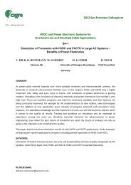
For comparison <strong>the</strong> EMTDC simulated as well as actual<br />
onsite recordings are presented for a DC line fault thrown at<br />
<strong>the</strong> George Town converter station overhead line while<br />
importing 100 MW from Vic<strong>to</strong>ria <strong>to</strong> Tasmania. Figures 7, 8<br />
<strong>and</strong> 9 show <strong>the</strong> actual system measurements (black traces)<br />
compared <strong>to</strong> <strong>the</strong> simulated EMTDC results (grey traces) for<br />
DC current, voltage <strong>and</strong> firing angle.<br />
350<br />
300<br />
250<br />
200<br />
150<br />
100<br />
50<br />
0<br />
-50<br />
0.9 1.4 1.9 2.4 sec<br />
Figure 7: DC Current – High Voltage (IdCH)<br />
The difference between measured <strong>and</strong> simulated current is<br />
caused by <strong>the</strong> integral portion of <strong>the</strong> frequency controller<br />
which leads <strong>to</strong> steady state offset modulation.<br />
50<br />
0<br />
0.9 1.4 1.9 2.4 sec<br />
-50<br />
-100<br />
-150<br />
-200<br />
-250<br />
-300<br />
-350<br />
-400<br />
-450<br />
Figure 8: DC Voltage – High Voltage Bus (UdCH)<br />
160<br />
155<br />
150<br />
145<br />
140<br />
135<br />
130<br />
125<br />
120<br />
115<br />
110<br />
0.9 1.4 1.9 2.4 sec<br />
Figure 9: Firing Angle (Alpha)<br />
IdCH_M<br />
IdCH_S<br />
George Town<br />
IdCH (Amps)<br />
UdCH_M<br />
UdCH_S<br />
George Town<br />
UdCH (kV)<br />
FiringA_M<br />
FiringA_S<br />
George Town<br />
Firing Angle<br />
(deg)
Conclusion<br />
Successful commissioning tests of <strong>the</strong> Basslink HVDC<br />
Interconnec<strong>to</strong>r proved <strong>the</strong> capability of <strong>the</strong> new Win-TDC<br />
control <strong>and</strong> protection system <strong>and</strong> its ability <strong>to</strong> flexibly adapt<br />
<strong>to</strong> project specific needs.<br />
References<br />
[1] National Electricity Market Management Company Ltd.,<br />
“An Introduction <strong>to</strong> Australia’s National Electricity<br />
Market”, p.6, ISBN 0-646-41233-7 (June 2005)<br />
[2] <strong>Siemens</strong> AG, Power Transmission <strong>and</strong> Distribution High<br />
Voltage Division, “Win-TDC – The State-of-<strong>the</strong>-Art<br />
<strong>Control</strong> <strong>and</strong> <strong>Protection</strong> System for HVDC Applications<br />
from <strong>Siemens</strong>” (June 2003)<br />
[3] Georg Wild, “Win-TDC The New Powerful HVDC<br />
<strong>Control</strong> <strong>and</strong> <strong>Protection</strong> System”, CIGRE-Colloquium on<br />
Role of HVDC, FACTS <strong>and</strong> Emerging Technologies in<br />
Evolving Power Systems, 17-24 September 2005,<br />
Bangalore, India