System Sensor i3 Smoke Detector - Wiley Systems
System Sensor i3 Smoke Detector - Wiley Systems
System Sensor i3 Smoke Detector - Wiley Systems

Create successful ePaper yourself
Turn your PDF publications into a flip-book with our unique Google optimized e-Paper software.
The i 3 Series heads and bases are keyed so that a 2-wire head will<br />
only mount to a 2-wire base, and a 4-wire head will only mount<br />
to a 4-wire base. The heads and bases are clearly identified as<br />
either 2-wire or 4-wire. When mounting the i 3 Series, ensure that<br />
the head is mounted to the correct base.<br />
Tamper-Resistant Feature<br />
The i 3 Series detectors include a tamper-resistant feature that prevents<br />
removal from the mounting base without the use of a tool.<br />
To engage the tamper-resistant feature, cut the small plastic tab<br />
located on the mounting base (Figure 2), and then install the<br />
detector. To remove the detector from the base once it has been<br />
made tamper resistant, use a small screwdriver to depress the<br />
square tamper release tab, located on the skirt of the mounting<br />
base, and turn the detector counterclockwise.<br />
Figure 2: Tamper-Resistant Feature<br />
DIRECT MOUNT<br />
HOLES<br />
Wire connections are made by stripping approximately 1 ⁄4-inch of<br />
insulation from the end of the feed wire, inserting it into the proper<br />
base terminal, and tightening the screw to secure the wire in<br />
place.<br />
Two-Wire Compatibility<br />
<strong>System</strong> <strong>Sensor</strong> two-wire smoke detectors are marked with a compatibility<br />
identifier located on the label on the back of the product.<br />
For two-wire models 2W-B and 2WT-B, connect detectors<br />
only to compatible alarm control panels as identified by <strong>System</strong><br />
<strong>Sensor</strong>’s compatibility chart. This chart contains the current list of<br />
detectors and UL Listed compatible control units. A copy of this<br />
list is available from <strong>System</strong> <strong>Sensor</strong> upon request.<br />
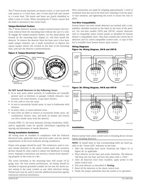
Wiring Diagrams<br />
Figure 3a: Wiring Diagram, 2W-B and 2WT-B<br />
2-WIRE<br />
ZONE<br />
+<br />
–<br />
EOL<br />
RESISTOR<br />
RA400Z<br />
RA400Z<br />
TAMPER<br />
RELEASE TAB<br />
SNAP OFF TAB<br />
FOR TAMPER LOCK<br />
A78-2711-00<br />
Do NOT Install <strong>Detector</strong>s in the Following Areas:<br />
• In or near areas where particles of combustion are normally<br />
present such as kitchens; in garages (vehicle exhaust); near<br />
furnaces, hot water heaters, or gas space heaters.<br />
• In very cold or very hot areas.<br />
• In wet or excessively humid areas, or next to bathrooms with<br />
showers.<br />
• In dusty, dirty, or insect-infested areas.<br />
• Near fresh air inlets or returns or excessively drafty areas. Air<br />
conditioners, heaters, fans, and fresh air intakes and returns<br />
can drive smoke away from the detector.<br />
2-WIRE<br />
CONTROL<br />
PANEL<br />
Figure 3b: Wiring Diagram, 4W-B and 4WT-B<br />
AUX OR<br />
SMOKE<br />
+<br />
POWER –<br />
IDC<br />
–<br />
+<br />
4-WIRE<br />
CONTROL<br />
PANEL<br />
(1) + IN<br />
(1) + IN<br />
(2) + OUT<br />
(2) + OUT<br />
(3) – IN/OUT<br />
(3) – IN/OUT<br />
(4) RA +<br />
2W-B or<br />
2WT-B<br />
(4) COM<br />
4W-B or<br />
4WT-B<br />
(5) RA –<br />
(5) NO<br />
(1) + IN<br />
(1) + IN<br />
(2) + OUT<br />
(2) + OUT<br />
(3) – IN/OUT<br />
(3) – IN/OUT<br />
(4) RA +<br />
2W-B or<br />
2WT-B<br />
(4) COM<br />
4W-B or<br />
4WT-B<br />
(5) RA –<br />
(5) NO<br />
A78-2714-00<br />
EOL<br />
RELAY<br />
(A77-716B)<br />
EOL<br />
RESISTOR<br />
Consult NFPA 72, the local Authority Having Jurisdiction (AHJ),<br />
and/or applicable codes for specific information regarding the<br />
spacing and placement of smoke detectors.<br />
Wiring Installation Guidelines<br />
All wiring must be installed in compliance with the National<br />
Electrical Code, applicable state and local codes, and any special<br />
requirements of the local Authority Having Jurisdiction.<br />
Proper wire gauges should be used. The conductors used to connect<br />
smoke detectors to the alarm control panel and accessory<br />
devices should be color-coded to reduce the likelihood of wiring<br />
errors. Improper connections can prevent a system from responding<br />
properly in the event of a fire.<br />
The screw terminals in the mounting base will accept 14–22<br />
gauge wire. For best system performance, all wiring should be<br />
installed in separate grounded conduit; do not mix fire alarm system<br />
wiring in the same conduit as any other electrical wiring.<br />
Twisted pair may be used to provide additional protection against<br />
extraneous electrical interference.<br />
Installation<br />
WARNING<br />
A78-2715-00<br />
Remove power from alarm control unit or initiating device circuits<br />
before installing detectors.<br />
NOTE: To install units so that corresponding LEDs are lined up,<br />
refer to the “Green LED” indicator on the base.<br />
1. Wire the mounting base screw terminals per Figure 3a or<br />
Figure 3b, as applicable.<br />
2. Place detector on the base and rotate clockwise. The detector<br />
will drop into the base and lock into place with a “click”.<br />
3. After all detectors have been installed, apply power to the<br />
alarm control unit.<br />
4. Test each detector as described in Testing.<br />
5. Reset all the detectors at the alarm control unit.<br />
6. Notify the proper authorities that the system is in operation.<br />
D100-96-00 2 I56-1800-02R