System Sensor i3 Smoke Detector - Wiley Systems
System Sensor i3 Smoke Detector - Wiley Systems
System Sensor i3 Smoke Detector - Wiley Systems

Create successful ePaper yourself
Turn your PDF publications into a flip-book with our unique Google optimized e-Paper software.
INSTALLATION AND MAINTENANCE INSTRUCTIONS<br />
Photoelectric <strong>Smoke</strong> <strong>Detector</strong><br />
Models:<br />
Series<br />
2W-B, 2WT-B<br />
4W-B, 4WT-B<br />
Before Installing<br />
Please read thoroughly <strong>System</strong> <strong>Sensor</strong> manual A05-1003,<br />
Application Guide: <strong>System</strong> <strong>Smoke</strong> <strong>Detector</strong>s, which provides<br />
detailed information on detector spacing, placement, zoning,<br />
wiring, and special applications. Copies of this manual are available<br />
from <strong>System</strong> <strong>Sensor</strong> at no charge.<br />
NOTICE: This manual shall be left with the owner/user of this<br />
equipment.<br />
IMPORTANT: This detector must be tested and maintained regularly<br />
following NFPA 72 requirements. At a minimum, cleaning<br />
should be performed annually.<br />
General Description<br />
Models 2W-B and 2WT-B are 2-wire photoelectric smoke detectors;<br />
models 4W-B and 4WT-B are 4-wire photoelectric smoke<br />
detectors. All models incorporate a state-of-the-art optical sensing<br />
chamber and an advanced microprocessor. The microprocessor<br />
allows the detector to automatically adjust its sensitivity back to<br />
the factory setting when it becomes more sensitive due to contaminants<br />
settling in its chamber. Should it become necessary, the<br />
screen/sensing chamber is field replaceable. Models 2WT-B and<br />
4WT-B also feature a restorable, built-in, fixed temperature<br />
(135°F) thermal detector and are also capable of sensing a freeze<br />
condition if the temperature is below 41°F.<br />
All i 3 Series detectors are designed to provide open area protection.<br />
Two-wire models must be used with compatible UL Listed<br />
panels only.<br />
When used with an i 3 Series compatible control panel or the i 3<br />
Series 2W-MOD module (refer to installation manual D500-46-00),<br />
the 2W-B and 2WT-B are capable of generating a “maintenance<br />
needed” signal. The 2W-MOD can indicate a need for cleaning,<br />
replacement, or a freeze condition (2WT-B only) at the control<br />
panel or module.<br />
Installation of the 2W-B, 2WT-B, 4W-B, and 4WT-B detectors is<br />
simplified by the use of a mounting base that may be pre-wired to<br />
the system, allowing the detector to be easily installed or<br />
removed. The mounting base installation is further simplified by<br />
the incorporation of features compatible with drywall fasteners.<br />
Two LEDs on the detector provide a local visual indication of the<br />
detector’s status:<br />
Table 1: <strong>Detector</strong> LED Modes<br />
| Green LED | Red LED<br />
Power-up | Blink 10 sec | Blink 10 sec<br />
Normal (standby) | Blink 5 sec | —<br />
Out of sensitivity | — | Blink 5 sec<br />
Freeze Trouble | — | Blink 10 sec<br />
Alarm | — | Solid<br />
3825 Ohio Avenue, St. Charles, Illinois 60174<br />
1-800-SENSOR2, FAX: 630-377-6495<br />
www.systemsensor.com<br />
After an initial power-up delay, the red and green LEDs will blink<br />
synchronously once every ten seconds. It will take approximately 80<br />
seconds for the detector to finish the power-up cycle (see Table 2).<br />
Table 2: Power-up Sequence for LED Status Indication*<br />
Condition<br />
| Duration<br />
Initial LED Status Indication<br />
| 80 seconds<br />
Initial LED Status Indication |<br />
(if excessive electrical noise is present) | 4 minutes<br />
*Refer to Electrical Specifications for power up to alarm time.<br />
NOTE: If, during power-up, the detector determines there is<br />
excessive electrical noise in the system such as those caused by<br />
improper grounding of the system or the conduit, both LEDs will<br />
blink for up to 4 minutes before displaying detector status (see<br />
Table 2).<br />
After power-up has completed and the detector is functioning normally<br />
within its listed sensitivity range, the green LED blinks once<br />
every five seconds. If the detector is in need of maintenance<br />
because its sensitivity has shifted outside the listed limits, the red<br />
LED blinks once every five seconds. When the detector is in the<br />
alarm mode, the red LED latches on. The LED indication must not<br />
be used in lieu of the tests specified under Testing. In a freeze<br />
trouble condition, the red LED will blink once every 10 seconds<br />
(refer to Table 1).<br />
To measure the detector’s sensitivity, the i 3 Series Model SENS-<br />
RDR Infrared Sensitivity Reader tool (see Figure 4) should be<br />
used.<br />
Models 2W-B and 2WT-B also include an output that allows an<br />
optional Model RA400Z Remote Annunciator to be connected.<br />
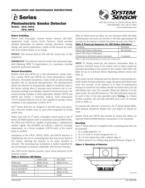
Mounting<br />
Each i 3 Series detector is supplied with a mounting base that can<br />
be mounted:<br />
1. To a single gang box, or<br />
2. To a 3 1 ⁄2-inch or 4-inch octagonal box, or<br />
3. To a 4-inch square box with a plaster ring, or<br />
4. Direct mount or to ceiling using drywall fasteners (Figure 2).<br />
Figure 1: Mounting of <strong>Detector</strong><br />
A78-2706-00<br />
D100-96-00 1 I56-1800-02R
The i 3 Series heads and bases are keyed so that a 2-wire head will<br />
only mount to a 2-wire base, and a 4-wire head will only mount<br />
to a 4-wire base. The heads and bases are clearly identified as<br />
either 2-wire or 4-wire. When mounting the i 3 Series, ensure that<br />
the head is mounted to the correct base.<br />
Tamper-Resistant Feature<br />
The i 3 Series detectors include a tamper-resistant feature that prevents<br />
removal from the mounting base without the use of a tool.<br />
To engage the tamper-resistant feature, cut the small plastic tab<br />
located on the mounting base (Figure 2), and then install the<br />
detector. To remove the detector from the base once it has been<br />
made tamper resistant, use a small screwdriver to depress the<br />
square tamper release tab, located on the skirt of the mounting<br />
base, and turn the detector counterclockwise.<br />
Figure 2: Tamper-Resistant Feature<br />
DIRECT MOUNT<br />
HOLES<br />
Wire connections are made by stripping approximately 1 ⁄4-inch of<br />
insulation from the end of the feed wire, inserting it into the proper<br />
base terminal, and tightening the screw to secure the wire in<br />
place.<br />
Two-Wire Compatibility<br />
<strong>System</strong> <strong>Sensor</strong> two-wire smoke detectors are marked with a compatibility<br />
identifier located on the label on the back of the product.<br />
For two-wire models 2W-B and 2WT-B, connect detectors<br />
only to compatible alarm control panels as identified by <strong>System</strong><br />
<strong>Sensor</strong>’s compatibility chart. This chart contains the current list of<br />
detectors and UL Listed compatible control units. A copy of this<br />
list is available from <strong>System</strong> <strong>Sensor</strong> upon request.<br />
Wiring Diagrams<br />
Figure 3a: Wiring Diagram, 2W-B and 2WT-B<br />
2-WIRE<br />
ZONE<br />
+<br />
–<br />
EOL<br />
RESISTOR<br />
RA400Z<br />
RA400Z<br />
TAMPER<br />
RELEASE TAB<br />
SNAP OFF TAB<br />
FOR TAMPER LOCK<br />
A78-2711-00<br />
Do NOT Install <strong>Detector</strong>s in the Following Areas:<br />
• In or near areas where particles of combustion are normally<br />
present such as kitchens; in garages (vehicle exhaust); near<br />
furnaces, hot water heaters, or gas space heaters.<br />
• In very cold or very hot areas.<br />
• In wet or excessively humid areas, or next to bathrooms with<br />
showers.<br />
• In dusty, dirty, or insect-infested areas.<br />
• Near fresh air inlets or returns or excessively drafty areas. Air<br />
conditioners, heaters, fans, and fresh air intakes and returns<br />
can drive smoke away from the detector.<br />
2-WIRE<br />
CONTROL<br />
PANEL<br />
Figure 3b: Wiring Diagram, 4W-B and 4WT-B<br />
AUX OR<br />
SMOKE<br />
+<br />
POWER –<br />
IDC<br />
–<br />
+<br />
4-WIRE<br />
CONTROL<br />
PANEL<br />
(1) + IN<br />
(1) + IN<br />
(2) + OUT<br />
(2) + OUT<br />
(3) – IN/OUT<br />
(3) – IN/OUT<br />
(4) RA +<br />
2W-B or<br />
2WT-B<br />
(4) COM<br />
4W-B or<br />
4WT-B<br />
(5) RA –<br />
(5) NO<br />
(1) + IN<br />
(1) + IN<br />
(2) + OUT<br />
(2) + OUT<br />
(3) – IN/OUT<br />
(3) – IN/OUT<br />
(4) RA +<br />
2W-B or<br />
2WT-B<br />
(4) COM<br />
4W-B or<br />
4WT-B<br />
(5) RA –<br />
(5) NO<br />
A78-2714-00<br />
EOL<br />
RELAY<br />
(A77-716B)<br />
EOL<br />
RESISTOR<br />
Consult NFPA 72, the local Authority Having Jurisdiction (AHJ),<br />
and/or applicable codes for specific information regarding the<br />
spacing and placement of smoke detectors.<br />
Wiring Installation Guidelines<br />
All wiring must be installed in compliance with the National<br />
Electrical Code, applicable state and local codes, and any special<br />
requirements of the local Authority Having Jurisdiction.<br />
Proper wire gauges should be used. The conductors used to connect<br />
smoke detectors to the alarm control panel and accessory<br />
devices should be color-coded to reduce the likelihood of wiring<br />
errors. Improper connections can prevent a system from responding<br />
properly in the event of a fire.<br />
The screw terminals in the mounting base will accept 14–22<br />
gauge wire. For best system performance, all wiring should be<br />
installed in separate grounded conduit; do not mix fire alarm system<br />
wiring in the same conduit as any other electrical wiring.<br />
Twisted pair may be used to provide additional protection against<br />
extraneous electrical interference.<br />
Installation<br />
WARNING<br />
A78-2715-00<br />
Remove power from alarm control unit or initiating device circuits<br />
before installing detectors.<br />
NOTE: To install units so that corresponding LEDs are lined up,<br />
refer to the “Green LED” indicator on the base.<br />
1. Wire the mounting base screw terminals per Figure 3a or<br />
Figure 3b, as applicable.<br />
2. Place detector on the base and rotate clockwise. The detector<br />
will drop into the base and lock into place with a “click”.<br />
3. After all detectors have been installed, apply power to the<br />
alarm control unit.<br />
4. Test each detector as described in Testing.<br />
5. Reset all the detectors at the alarm control unit.<br />
6. Notify the proper authorities that the system is in operation.<br />
D100-96-00 2 I56-1800-02R
Dust covers are an effective way to limit the entry of dust into<br />
the smoke detector sensing chamber. However, they may not<br />
completely prevent airborne dust particles from entering the<br />
detector. Therefore, <strong>System</strong> <strong>Sensor</strong> recommends the removal of<br />
detectors before beginning construction or other dust producing<br />
activity. When returning the system to service, be sure to remove<br />
the dust covers from any detectors that were left in place during<br />
construction.<br />
Testing<br />
<strong>Detector</strong>s must be tested after installation and following<br />
maintenance.<br />
NOTE: Before testing, notify the proper authorities that maintenance<br />
is being performed and the system will be temporarily out<br />
of service. Disable the zone or system undergoing maintenance to<br />
prevent any unwanted alarms.<br />
Ensure proper wiring and power is applied. After power up, allow<br />
80 seconds for the detector to stabilize before testing.<br />
Test i 3 Series detectors as follows:<br />
A. Test Switch<br />
1. An opening for the recessed test switch is located on the<br />
detector housing (See Figure 4).<br />
2. Insert a small screwdriver or allen wrench (0.18″ max.) into<br />
the test switch opening; push and hold.<br />
3. If the detector is within the listed sensitivity limits, the<br />
detector’s red LED should light within five seconds.<br />
Figure 4: Recessed Test Switch Opening and SENS-RDR<br />
Position<br />
RECESSED TEST SWITCH<br />
LED<br />
CAUTION<br />
POSITION SENS-RDR<br />
VERTICALLY TO<br />
OVAL AREA BY THE<br />
WORD “PAINT”<br />
PUSH RECESSED<br />
SWITCH WITH A<br />
0.18″ MAX.<br />
DIAMETER TOOL<br />
A78-2712-00<br />
B. <strong>Smoke</strong> Entry Test<br />
Hold a smoldering punk stick or cotton wick at the side of the<br />
detector and gently blow the smoke through the detector until<br />
it alarms.<br />
C. Direct Heat Method (models 2WT-B and 4WT-B only)<br />
Using a 1000-1500 watt hair dryer, direct the heat toward either<br />
of the thermistors. Hold the heat source about 12 inches from<br />
the detector to avoid damage to the plastic.<br />
NOTE: For the above tests, the detector will reset only after the<br />
power source has been momentarily interrupted.<br />
Loop Verification (models 2W-B and 2WT-B only)<br />
Loop verification is provided by the EZ Walk loop test feature.<br />
This feature is for use with i 3 Series compatible control panels or<br />
the i 3 Series 2W-MOD module only. The EZ Walk loop test verifies<br />
the initiating loop wiring and provides visual status indication<br />
at each detector.<br />
1. Ensure proper wiring and power is applied. Wait approximately<br />
six minutes before performing EZ Walk test.<br />
2. Place control panel or module in EZ Walk Test mode (refer<br />
to panel manufacturer’s manual or 2W-MOD manual D500-<br />
46-00).<br />
3. Observe the LEDs on each detector:<br />
Table 3: EZ Walk Test <strong>Detector</strong> Modes<br />
|Green LED |Red LED<br />
Proper Operation |Double blink 5 sec |—<br />
Out of Sensitivity |— |Double Blink 5 sec<br />
Freeze Condition |— |Double Blink 10 sec<br />
NOTE: The EZ Walk loop test must not be used instead of alarm<br />
testing.<br />
Maintenance<br />
NOTE: Before performing maintenance on the detector, notify the<br />
proper authorities that maintenance is being performed and the<br />
system will be temporarily out of service. Disable the zone or system<br />
undergoing maintenance to prevent any unwanted alarms.<br />
1. Remove the detector cover by turning counterclockwise. (See<br />
Figure 5.)<br />
2. Vacuum the cover or use canned air to remove any dust or<br />
debris.<br />
3. Remove the top half of the screen/sensing chamber by lifting<br />
straight up (Figure 5).<br />
4. Vacuum or use canned air to remove any dust or particles that<br />
are present on both chamber halves.<br />
5. Replace the top half of the screen/sensing chamber by aligning<br />
the arrow on the screen/sensing chamber with the arrow on<br />
the housing. Press down firmly until the screen/sensing chamber<br />
is fully seated.<br />
6. Replace the detector cover by placing it over the screen/sensing<br />
chamber and turning it clockwise until it snaps into place.<br />
7. Reinstall the detector and test. (See the Testing section.)<br />
8. Notify the proper authorities when the system is back in service.<br />
Figure 5: Removing/Replacing Screen/Sensing Chamber<br />
REMOVABLE<br />
DETECTOR<br />
COVER<br />
SCREEN/SENSING<br />
CHAMBER<br />
(TOP HALF)<br />
If a detector fails any of the above test methods, its wiring should<br />
be checked and it should be cleaned as outlined in the<br />
Maintenance section. If the detector still fails, it should be<br />
replaced.<br />
Notify the proper authorities when the system is back in service.<br />
DETECTOR<br />
HOUSING<br />
A78-2713-00<br />
D100-96-00 3 I56-1800-02R
Electrical Specifications 2-wire 4-wire<br />
<strong>System</strong> Voltage – Nominal: 12/24 12/24 Volts Non-polarized<br />
Min.: 8.5 8.5 Volts<br />
Max.: 35 35 Volts<br />
Max. Ripple Voltage: 30 30 % of nominal<br />
peak to peak<br />
Max. Standby Current: 50 50 µA average<br />
Peak Standby Current: 100 — µA<br />
Max. Start-up Capacitance: 0.1 — µF<br />
Latching Alarm: Reset by momentary power interruption<br />
Maximum Initial<br />
Start-up Time: 45 15 sec<br />
Power-up Time<br />
after 10 sec. reset: 15 15 sec<br />
Max. Alarm Current: 130 20 mA 12 Volt <strong>System</strong>s<br />
(For 2W-B and 2WT-B,<br />
panel must limit current) 130 23 mA 24 Volt <strong>System</strong>s<br />
Alarm Contact Ratings: — 0.5 Amp @ 30 V AC/DC<br />
Alarm Reset Voltage: 2.5 2.5 Volts<br />
Alarm Reset Time: 0.3 0.3 sec<br />
Physical Specifications<br />
Heat <strong>Sensor</strong><br />
(Model 2WT-B and 4WT-B): 135°F (57.2°C)<br />
Freeze Trouble<br />
(Model 2WT-B and 4WT-B): 41°F (5°C)<br />
Operating Temperature Range:<br />
2W-B and 4W-B:<br />
32 to 120°F (0 to 49°C)<br />
2WT-B and 4WT-B: 32 to 100°F (0 to 37.8°C)<br />
Operating Humidity Range: 0 to 95% RH non-condensing<br />
Storage Temperature Range: –4 to 158°F (–20 to 70°C)<br />
Diameter (including base): 5.3 inches<br />
Height (including base): 2.0 inches<br />
Weight:<br />
6.3 oz.<br />
Please refer to insert for the Limitations of Fire Alarm <strong>System</strong>s<br />
<strong>System</strong> <strong>Sensor</strong> warrants its enclosed smoke detector to be free from defects in<br />
materials and workmanship under normal use and service for a period of three<br />
years from date of manufacture. <strong>System</strong> <strong>Sensor</strong> makes no other express warranty<br />
for this smoke detector. No agent, representative, dealer, or employee of the<br />
Company has the authority to increase or alter the obligations or limitations of<br />
this Warranty. The Company’s obligation of this Warranty shall be limited to the<br />
repair or replacement of any part of the smoke detector which is found to be<br />
defective in materials or workmanship under normal use and service during the<br />
three year period commencing with the date of manufacture. After phoning<br />
<strong>System</strong> <strong>Sensor</strong>’s toll free number 800-SENSOR2 (736-7672) for a Return<br />
Authorization number, send defective units postage prepaid to: <strong>System</strong> <strong>Sensor</strong>,<br />
Three-Year Limited Warranty<br />
Repair Department, RA #__________, 3825 Ohio Avenue, St. Charles, IL 60174.<br />
Please include a note describing the malfunction and suspected cause of failure.<br />
The Company shall not be obligated to repair or replace units which are found to<br />
be defective because of damage, unreasonable use, modifications, or alterations<br />
occurring after the date of manufacture. In no case shall the Company be liable<br />
for any consequential or incidental damages for breach of this or any other<br />
Warranty, expressed or implied whatsoever, even if the loss or damage is caused<br />
by the Company’s negligence or fault. Some states do not allow the exclusion or<br />
limitation of incidental or consequential damages, so the above limitation or<br />
exclusion may not apply to you. This Warranty gives you specific legal rights, and<br />
you may also have other rights which vary from state to state.<br />
FCC Statement<br />
This device complies with part 15 of the FCC Rules. Operation is subject to the following two conditions: (1) This device may not cause harmful interference, and (2) this<br />
device must accept any interference received, including interference that may cause undesired operation.<br />
Note: This equipment has been tested and found to comply with the limits for a Class B digital device, pursuant to Part 15 of the FCC Rules. These limits are designed to provide<br />
reasonable protection against harmful interference in a residential installation. This equipment generates, uses and can radiate radio frequency energy and, if<br />
not installed and used in accordance with the instructions, may cause harmful interference to radio communications. However, there is no guarantee that interference<br />
will not occur in a particular installation. If this equipment does cause harmful interference to radio or television reception, which can be determined by turning the<br />
equipment off and on, the user is encouraged to try to correct the interference by one or more of the following measures:<br />
– Reorient or relocate the receiving antenna.<br />
– Increase the separation between the equipment and receiver.<br />
– Connect the equipment into an outlet on a circuit different from that to which the receiver is connected.<br />
– Consult the dealer or an experienced radio/TV technician for help.<br />
D100-96-00 4 I56-1800-02R<br />
©<strong>System</strong> <strong>Sensor</strong> 2001