BHEL-ISG 2 X 250 MW BARAUNI THERMAL POWER STATION ...
BHEL-ISG 2 X 250 MW BARAUNI THERMAL POWER STATION ...
BHEL-ISG 2 X 250 MW BARAUNI THERMAL POWER STATION ...

Create successful ePaper yourself
Turn your PDF publications into a flip-book with our unique Google optimized e-Paper software.
<strong>BHEL</strong>-<strong>ISG</strong><br />
2 X <strong>250</strong> <strong>MW</strong> <strong>BARAUNI</strong> <strong>THERMAL</strong> <strong>POWER</strong><br />
<strong>STATION</strong><br />
Technical Specification for<br />
Piling, Civil, Structural & Architectural Works<br />
SPECIFICATION NO<br />
IS- 1-10-2013 /005<br />
DATE:04/06/2011<br />
VOLUME-2<br />
SL<br />
No.<br />
SECTION<br />
NUMBER<br />
TITLE<br />
PAGES<br />
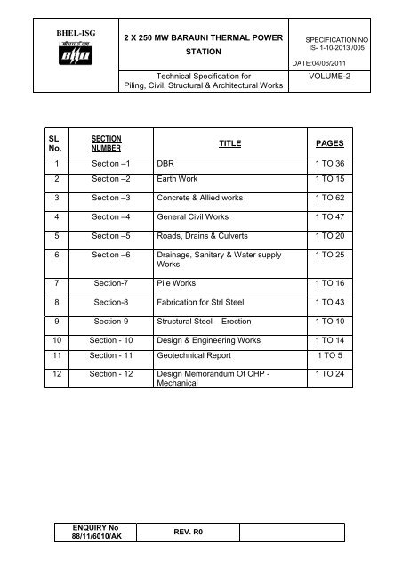
1 Section –1 DBR 1 TO 36<br />
2 Section –2 Earth Work 1 TO 15<br />
3 Section –3 Concrete & Allied works 1 TO 62<br />
4 Section –4 General Civil Works 1 TO 47<br />
5 Section –5 Roads, Drains & Culverts 1 TO 20<br />
6 Section –6 Drainage, Sanitary & Water supply<br />
Works<br />
1 TO 25<br />
7 Section-7 Pile Works 1 TO 16<br />
8 Section-8 Fabrication for Strl Steel 1 TO 43<br />
9 Section-9 Structural Steel – Erection 1 TO 10<br />
10 Section - 10 Design & Engineering Works 1 TO 14<br />
11 Section - 11 Geotechnical Report 1 TO 5<br />
12 Section - 12 Design Memorandum Of CHP -<br />
Mechanical<br />
1 TO 24<br />
ENQUIRY No<br />
88/11/6010/AK<br />
REV. R0
<strong>BHEL</strong>-<strong>ISG</strong><br />
2 X <strong>250</strong> <strong>MW</strong> <strong>BARAUNI</strong> <strong>THERMAL</strong> <strong>POWER</strong><br />
<strong>STATION</strong><br />
Design Criteria for Piling, Civil, Structural<br />
& Architectural Works<br />
SPECIFICATION NO<br />
IS- 1-10-2013 /005<br />
DATE:04/06/2011<br />
VOLUME 2 /<br />
SECTION 1<br />
SECTION 1:<br />
DESIGN BASIS REPORT<br />
Enquiry No<br />
88/11/6010/AK<br />
Rev no R00
<strong>BHEL</strong>-<strong>ISG</strong><br />
2 X <strong>250</strong> <strong>MW</strong> <strong>BARAUNI</strong> <strong>THERMAL</strong> <strong>POWER</strong><br />
<strong>STATION</strong><br />
Design Criteria for Piling, Civil, Structural<br />
& Architectural Works<br />
SPECIFICATION NO<br />
IS- 1-10-2013 /005<br />
DATE:04/06/2011<br />
VOLUME 2 /<br />
SECTION 1<br />
CONTENTS: -<br />
Clause No Sub-Clause<br />
Description<br />
No<br />
1.0 General<br />
2.0 Project Information<br />
2.1 Site Specific Project Data<br />
3.0 Soil Condition, Ground Water Table, Bearing<br />
Capacity<br />
4.0 Applicable Codes, Standards & Specifications<br />
4.1 Materials<br />
5.0 Design Loads<br />
5.1 Dead Loads<br />
5.2 Imposed Loads<br />
5.3 Surcharge Loads<br />
5.4 Earth Pressure Loads<br />
5.5 Wind Loads<br />
5.6 Seismic Loads<br />
5.7 Equipment Loads<br />
5.8 Material Loads<br />
6.0 Load Combinations<br />
6.1 Basic Load Cases<br />
6.2 Load Combinations<br />
6.3 Load Combinations for Underground Structures<br />
7.0 Design Methodology of Reinforced Concrete<br />
Structures<br />
8.0 Design Methodology of Steel Structures<br />
9.0 Paintings<br />
10.0 Specific requirement & Design Philosophy of<br />
Buildings & Structures of Solid Material Handling<br />
System<br />
11.0 Material & Finishing Specification<br />
11.1 Material Specification<br />
11.2 Finishing Specification<br />
11.3 Miscellaneous Specification<br />
Enquiry No<br />
88/11/6010/AK<br />
Rev no R00<br />
Page no: 1 of 37
<strong>BHEL</strong>-<strong>ISG</strong><br />
2 X <strong>250</strong> <strong>MW</strong> <strong>BARAUNI</strong> <strong>THERMAL</strong> <strong>POWER</strong><br />
<strong>STATION</strong><br />
Design Criteria for Piling, Civil, Structural<br />
& Architectural Works<br />
SPECIFICATION NO<br />
IS- 1-10-2013 /005<br />
DATE:04/06/2011<br />
VOLUME 2 /<br />
SECTION 1<br />
1.0. GENERAL<br />
Bihar State Electricity Board (BSEB) is setting up a Coal fired Thermal Power plant at<br />
Barauni, Begusarai District, and Bihar. The capacity of the proposed thermal power project is<br />
500<strong>MW</strong> with 2 x <strong>250</strong> <strong>MW</strong> configurations with sub – critical steam parameters. The power<br />
generated from the plant will be sold to BIHAR as well as to other states through interstate<br />
transmission system. <strong>BHEL</strong> is the EPC contractor for the above.<br />
This document deals mainly with the technical specifications needed for the design and<br />
preparation of detailed drawings, getting the designs and drawings approved by the<br />
Engineering, fabrication, erection and construction of the necessary civil, structural and<br />
architectural works associated with the coal and ash handling plant to be installed at 2 X <strong>250</strong><br />
BSEB Barauni Thermal Power Project. This document also indicates the general description<br />
of facilities, description of structural framing system, applicable design codes and standards,<br />
specific design criteria, design loads and combinations, design methodology and construction<br />
materials proposed to be adopted for all the works in the project.<br />
The specifications are intended for the general description of the work, quality and<br />
workmanship. However, the specifications are not intended to cover minute details and the<br />
work shall be executed according to the relevant latest Indian Standard Codes/I.R.S. /I.R.C.<br />
specifications.<br />
2.0. SOIL CONDITION, GROUND WATER TABLE AND BEARING CAPACITY<br />
From the Interim Geotechnical Investigation, it was found that the entire area of the proposed<br />
Thermal Power Plant was found filled up by fly ash layers up to a depth of 10.5m. Hence<br />
placing foundations will produce adverse effect without adopting any suitable ground<br />
improvement technique.<br />
Increasing trend in N-value below 10.5m depth indicate soil strata of medium dense, dense<br />
and very dense of relative density.<br />
During interim field investigation the water table was recorded between 3.68m & 10.10m<br />
showing variability in water table at site.<br />
The following are the Net Allowable Bearing Capacities of foundation soil for 25mm<br />
settlement:<br />
Up to 10.5 m depth (N=4) = 2.2 t/m2<br />
Beyond 10.5 m depth (Average N =14) = 7.7 t/m2<br />
Enquiry No<br />
88/11/6010/AK<br />
Rev no R00<br />
Page no: 2 of 37
<strong>BHEL</strong>-<strong>ISG</strong><br />
2 X <strong>250</strong> <strong>MW</strong> <strong>BARAUNI</strong> <strong>THERMAL</strong> <strong>POWER</strong><br />
<strong>STATION</strong><br />
Design Criteria for Piling, Civil, Structural<br />
& Architectural Works<br />
SPECIFICATION NO<br />
IS- 1-10-2013 /005<br />
DATE:04/06/2011<br />
VOLUME 2 /<br />
SECTION 1<br />
As such the Net Allowable BC as assessed above are of lower order for settlement criteria.<br />
On the basis of the interim field investigation, the following observations/suggestions have<br />
been offered:<br />
• A simple method of construction of granular piles / stone column alternative to fibro<br />
floatation / fibro replacement methods are suggested to use which will prove<br />
beneficial to reduce settlement and improve bearing capacity.<br />
• Considering the safety of the structures of the industrial building, the cast- in-situ<br />
piles of Diameter 600mm and 750 mm and length about 20m to 22m after the cut off<br />
level from the existing ground level will be more appropriate.<br />
However, the final lengths, dimensions and other specifications of Piles will be given only<br />
after the Detailed Geotechnical Investigation has been carried out.<br />
3.0. APPLICABLE CODES, STANDARDS & SPECIFICATIONS<br />
The pertinent clauses and sections of Bureau of Indian Standards publications and bearing the<br />
prefix IS with all amendments will be applicable to the material, design, detailing, fabrication,<br />
construction, testing etc. It is not intended to list out all the applicable IS codes, but the list of<br />
most frequently used BIS codes are furnished.<br />
IS Code<br />
IS:432-1982<br />
IS:456-2000<br />
Description of the Code<br />
Specification for mild steel and medium tensile<br />
steel bars for concrete reinforcement.<br />
Code of Practice for plain and reinforced concrete<br />
IS 458 : 2003 Precast Concrete Pipes (with and without<br />
Reinforcement) - Specification<br />
IS 783 : 1985<br />
Code of practice for laying of concrete pipes<br />
IS:800-<br />
1984/2007<br />
IS:814-2004<br />
IS:816-1969<br />
IS: 875 (Part 1-<br />
5)-1987<br />
Code of Practice for general construction in steel<br />
Specification for covered electrodes for metal arc<br />
welding for weld steel.<br />
Code of Practice for use of metal arc welding for<br />
general construction in mild steel<br />
Code of Practice for design loads (other than<br />
earthquake) for Buildings and structures.<br />
IS:1038-1983 Specification for steel doors, windows and<br />
ventilators<br />
Enquiry No<br />
88/11/6010/AK<br />
Rev no R00<br />
Page no: 3 of 37
<strong>BHEL</strong>-<strong>ISG</strong><br />
2 X <strong>250</strong> <strong>MW</strong> <strong>BARAUNI</strong> <strong>THERMAL</strong> <strong>POWER</strong><br />
<strong>STATION</strong><br />
Design Criteria for Piling, Civil, Structural<br />
& Architectural Works<br />
SPECIFICATION NO<br />
IS- 1-10-2013 /005<br />
DATE:04/06/2011<br />
VOLUME 2 /<br />
SECTION 1<br />
IS 1079 : 1994 Hot Rolled Carbon Steel Sheets and Strips -<br />
Specification<br />
IS:1161-1998<br />
IS:1361-1978<br />
IS: 1363 (Part 1-<br />
2)-2002<br />
IS: 1363 (Part 3)-<br />
1992<br />
IS: 1364 (Part 1-<br />
3)-2002<br />
IS: 1364 (Part 4)-<br />
2003<br />
IS: 1364 (Part 5-<br />
6)-2002<br />
IS: 1367 (Part 1-<br />
20)<br />
IS:1786-1985<br />
IS:1893-2002<br />
(All Parts)<br />
IS:1904-1986<br />
IS:1948-1961<br />
IS:2062-2006<br />
IS:2950(Part 1)-<br />
1981<br />
IS : 2911-1979<br />
IS : 2911-1979<br />
IS : 2911-1985<br />
IS:2974(Part 1)-<br />
1982<br />
Steel tubes for structural purposes<br />
Steel windows for industrial buildings.<br />
Hexagon head bolts, screws and nuts of<br />
production grade C.<br />
Hexagon head bolts, screws and nuts of<br />
production grade C.<br />
Hexagon head bolts, screws and nuts of<br />
production grades A & B.<br />
Hexagon head bolts, screws and nuts of<br />
production grades A & B.<br />
Hexagon head bolts, screws and nuts of<br />
production grades A & B.<br />
Technical supply conditions for threaded<br />
fasteners.<br />
Specification for high strength deformed steel bars<br />
and wires for concrete reinforcement.<br />
Criteria for earthquake resistant design of<br />
Structures<br />
Code of practice for design and construction of<br />
foundations in soils<br />
Specification for aluminium doors, windows and<br />
ventilators<br />
Steel for general structural purposes<br />
Code of practice for design & construction of raft<br />
foundations<br />
Code of practice for design and construction of<br />
pile foundations. (Part-1/Sec.1) Driven cast in situ<br />
concrete piles.<br />
Code of practice for design and construction of<br />
pile foundations. (Part-1/Sec.2) Bored cast-in-situ<br />
concrete piles.<br />
Code of practice for design and construction of<br />
pile foundations. (Part-IV) Load test on piles<br />
Code of practice for design & construction of<br />
machine foundations.<br />
Enquiry No<br />
88/11/6010/AK<br />
Rev no R00<br />
Page no: 4 of 37
<strong>BHEL</strong>-<strong>ISG</strong><br />
2 X <strong>250</strong> <strong>MW</strong> <strong>BARAUNI</strong> <strong>THERMAL</strong> <strong>POWER</strong><br />
<strong>STATION</strong><br />
Design Criteria for Piling, Civil, Structural<br />
& Architectural Works<br />
SPECIFICATION NO<br />
IS- 1-10-2013 /005<br />
DATE:04/06/2011<br />
VOLUME 2 /<br />
SECTION 1<br />
IS:2974(Part 2)-<br />
1980<br />
IS:2974(Part 3)-<br />
1992<br />
IS:2974(Part 4)-<br />
1979<br />
IS:2974(Part 5)-<br />
1987<br />
IS:3370(Part 1-<br />
2)-1967<br />
IS:3370(Part 3-<br />
4)-1967<br />
IS:3502-19940<br />
IS:4326-1993a<br />
IS:4351-2003<br />
IS:4995-1974<br />
IS: 5624-1993<br />
IS: 6248-1979<br />
IS: 6403-1981<br />
IS: 7215-1974<br />
IS: 8009 (Part 1)-<br />
1976<br />
IS: 8009 (Part 2)-<br />
1980<br />
IS:9595-1996<br />
Code of practice for design & construction of<br />
machine foundations.<br />
Code of practice for design & construction of<br />
machine foundations.<br />
Code of practice for design & construction of<br />
machine foundations.<br />
Code of practice for design & construction of<br />
machine foundations.<br />
Code of Practice for concrete structures for the<br />
storage of liquids:<br />
Code of Practice for concrete structures for the<br />
storage of liquids:<br />
Steel Chequered Plates<br />
Code of Practice for earthquake resistant design<br />
and construction of buildings<br />
Specification for steel door frames.<br />
Criteria for design of reinforced concrete bins for<br />
storage of granular and powdery materials (All<br />
parts)<br />
Foundation Bolts<br />
Specification for metal rolling shutters and rolling<br />
grills.<br />
Code for determination of bearing capacity of<br />
shallow foundations.<br />
Tolerances for fabrication steel structures.<br />
Code of practice for calculation of settlement of<br />
foundations-shallow foundations.<br />
Code of practice for calculation of settlement of<br />
foundations-deep foundations.<br />
Recommendations for Metal arc welding of carbon<br />
and carbon manganese steel<br />
IS :10262-1982 Recommended guidelines for concrete mix<br />
design.<br />
IS:11592-2000 Selection and design of belt conveyors<br />
IS: 12843-1989 Tolerance for erection of steel structures.<br />
IS 13920 : 1993 Ductile detailing of reinforced concrete structures<br />
subjected to seismic forces - Code of practice<br />
Enquiry No<br />
88/11/6010/AK<br />
Rev no R00<br />
Page no: 5 of 37
<strong>BHEL</strong>-<strong>ISG</strong><br />
2 X <strong>250</strong> <strong>MW</strong> <strong>BARAUNI</strong> <strong>THERMAL</strong> <strong>POWER</strong><br />
<strong>STATION</strong><br />
Design Criteria for Piling, Civil, Structural<br />
& Architectural Works<br />
SPECIFICATION NO<br />
IS- 1-10-2013 /005<br />
DATE:04/06/2011<br />
VOLUME 2 /<br />
SECTION 1<br />
IS: 14246-1995<br />
SP-7-2005<br />
BS 5493:1977<br />
Indian Railway<br />
Code<br />
Continuously pre-painted galvanised steel sheets<br />
and coils.<br />
National building code of India.<br />
Code of practice for protective coating of iron and<br />
steel structures against corrosion<br />
Indian Railway standard code of practice for<br />
design of Railway load bearing structure.<br />
NOTE: All the IS codes used should be the latest versions.<br />
3.1. Materials<br />
The following table gives the most commonly used material in the project under<br />
consideration. However all the materials used in the works will conform to relevant BIS.<br />
S No Material Reference Codes /<br />
Standards<br />
1. Cement OPC Grade 43 IS:8112-1989<br />
2. Specification for Portland slag cement IS:455-1989<br />
3. Coarse Aggregates IS:383-1970<br />
4. Fine Aggregates IS:383-1970<br />
5. Reinforcement Steel- Mild Steel IS:432 grade 1-<br />
1982<br />
6. Reinforcement Steel-HYSD Bars IS:1786-2008<br />
7. Steel for general structural purposes IS:2062- Grade A &<br />
B-2006<br />
8. Burnt Clay bricks ( Min 50 kg/cm²) IS: 1077-<br />
1992<br />
9. Specification for Portland pozzolana cement<br />
Part 1 Flyash based<br />
IS 1489:Part<br />
1:1991<br />
10. Flyash Clay bricks IS: 13757-<br />
1993<br />
11. Water for concrete/ masonry works IS:456-2000<br />
12. MS Steel Tubes IS:1161-1998<br />
13. Steel Doors & ventilators IS:1038-1983<br />
Enquiry No<br />
88/11/6010/AK<br />
Rev no R00<br />
Page no: 6 of 37
<strong>BHEL</strong>-<strong>ISG</strong><br />
4.0 DESIGN LOADS<br />
2 X <strong>250</strong> <strong>MW</strong> <strong>BARAUNI</strong> <strong>THERMAL</strong> <strong>POWER</strong><br />
<strong>STATION</strong><br />
Design Criteria for Piling, Civil, Structural<br />
& Architectural Works<br />
14. Steel windows for industrial buildings IS:1361-1978<br />
15. Galvanised Steel Sheets (Plain and<br />
IS: 277-2003<br />
Corrugated)<br />
16. PVC Water Stop IS: 12200-2001<br />
17. Sealing Compounds for joints in concrete IS: 1834-1984<br />
18. Ready mixed paint, brushing, bituminous,<br />
black, lead-free, acid, alkali and heat resisting<br />
19. Specification for Expanded Metal Steel<br />
Sheets for General Purposes<br />
20. Specification for ceramic unglazed vitreous<br />
acid resisting tile<br />
21. Specification for chemical resistant mortars:<br />
Part I Silicate type<br />
22. Specification for Chemical Resistant Mortars -<br />
Part II : Resin type<br />
23. Specification for chemical resistant mortars:<br />
Part III Sulphur type<br />
24. Specification for bitumen mastic acid-resisting<br />
grade<br />
SPECIFICATION NO<br />
IS- 1-10-2013 /005<br />
DATE:04/06/2011<br />
VOLUME 2 /<br />
SECTION 1<br />
All structures shall be designed for the most critical combinations of dead loads, imposed<br />
loads, equipment loads (including impact / vibration), crane loads, monorails loads etc. and<br />
other loads such as wind loads, seismic loads and any other loads likely to be experienced<br />
by the structures during the design life of the structures / building. Suitable expansion joints<br />
shall be provided as per the stipulations of BIS codes to take care of thermal movements<br />
4.1. DEAD LOADS:<br />
IS 158-1981<br />
IS 412-1975<br />
IS 4457-1982<br />
IS 4832: Part<br />
1:1969<br />
IS 4832: Part<br />
2:1969<br />
IS 4832: Part<br />
3:1968<br />
IS 9510: 1980<br />
Dead load on the structure will include self weight with all finishes and fixtures, piping,<br />
ducting, cable etc including all likely permanent loads to be experienced by the structure<br />
during its life time.<br />
For computation of loads, unit weight of materials as given in IS: 875 (Part-1) shall be<br />
considered. Wherever unit weights are not available in the BIS Codes, manufacturer’s<br />
recommended weights shall be considered.<br />
4.2. IMPOSED LOADS: If the erection load is higher than the above specified live loads on<br />
any floor or part thereof, then the erection loads are to be considered for the design.<br />
Enquiry No<br />
88/11/6010/AK<br />
Rev no R00<br />
Page no: 7 of 37
<strong>BHEL</strong>-<strong>ISG</strong><br />
2 X <strong>250</strong> <strong>MW</strong> <strong>BARAUNI</strong> <strong>THERMAL</strong> <strong>POWER</strong><br />
<strong>STATION</strong><br />
Design Criteria for Piling, Civil, Structural<br />
& Architectural Works<br />
SPECIFICATION NO<br />
IS- 1-10-2013 /005<br />
DATE:04/06/2011<br />
VOLUME 2 /<br />
SECTION 1<br />
S.<br />
No<br />
Area / Location<br />
1 Flat roof ( Accessible roofs)<br />
2 Flat roof ( Non-accessible roofs)<br />
Imposed Loads in kg /m²<br />
150 (IL) +100 (Dust<br />
Load) = <strong>250</strong><br />
75 (IL) + 125 ( Dust<br />
Load ) = 225<br />
3 Sloped / inclined roof As per IS 875 for IL +<br />
75kg/m 2 (DL) i.e. Dust<br />
load<br />
4 R.C.C. floors 500<br />
5 Stairs, landings and balconies 500<br />
6 Toilet rooms 200<br />
7 Access Platforms 500<br />
8 Walkways (including walkways in<br />
conveyor galleries) cross overs,<br />
service platforms & maintenance<br />
300<br />
platforms<br />
9 Spillage Loads ( as per IS 11592,<br />
Cal 8.14.2.3) on Gallery walk way,<br />
100<br />
JT, Crusher floor<br />
10 MCC floors 1000<br />
11 Road Culverts and its allied<br />
structures including R.C.C. pipe<br />
crossing & road crossing of<br />
trenches.<br />
For class 'AA' loading<br />
and checked for class A<br />
loading as per IRC<br />
standard.<br />
12 Covers for trenches/ channels 400<br />
13 Sumps & tanks and other underground<br />
basement type structures<br />
including Channels / Trenches<br />
14 For other moving parts of<br />
Conveyor as per IS: 11592 Cal:<br />
8.14.2.2.<br />
A surcharge of 2T/m 2 in<br />
addition to other loads.<br />
1.1 times for all moving<br />
parts such as material<br />
on belt, belt, moving /<br />
rotating parts of the<br />
conveyor system to<br />
cater for dynamic loads.<br />
Enquiry No<br />
88/11/6010/AK<br />
Rev no R00<br />
Page no: 8 of 37
<strong>BHEL</strong>-<strong>ISG</strong><br />
2 X <strong>250</strong> <strong>MW</strong> <strong>BARAUNI</strong> <strong>THERMAL</strong> <strong>POWER</strong><br />
<strong>STATION</strong><br />
Design Criteria for Piling, Civil, Structural<br />
& Architectural Works<br />
SPECIFICATION NO<br />
IS- 1-10-2013 /005<br />
DATE:04/06/2011<br />
VOLUME 2 /<br />
SECTION 1<br />
4.3 Surcharge loads<br />
For channels, sumps, tanks and other underground basement type structures, a<br />
surcharge pressure of 2.0 t/m 2 shall be considered in addition to earth pressure,<br />
water pressure, etc. for design. For minor underground structures such as cable/pipe<br />
trenches, surcharge load of 1.0 t/m² shall be considered.<br />
4.4 Earth Pressure Loads<br />
Earth pressure (horizontal pressure of the soil) for all underground structures shall<br />
be calculated using coefficient of earth pressure at rest or coefficient of active or<br />
passive earth pressure (whichever is applicable) depending upon the structural<br />
configuration.<br />
The earth pressure including the surcharge load shall be calculated as follows:<br />
p o = K(γ h + q), Where<br />
γ = Unit weight of soil (saturated) (kN/m 3 )<br />
h = position of earth pressure p 0 from ground surface (m)<br />
q = surcharge load<br />
K = Earth pressure co-efficient, K0 Ka Kp (whichever is applicable)<br />
K0 = Coefficient of Earth pressure at rest<br />
Ka = Coefficient of Earth pressure for active case<br />
Kp = Coefficient of Earth pressure for passive case<br />
φ = internal friction angle<br />
4.5 Wind loads<br />
All exposed structures or parts of structures shall be designed to resist the pressures<br />
due to wind in any direction in accordance with IS 875 -1987 (Part 3). The evaluation<br />
of the design wind speed and pressures shall be made on the basis of the following<br />
parameters:<br />
Basic wind speed at 10m above ground<br />
(V b )<br />
47 m/sec<br />
Risk coefficient k 1 1.07<br />
Terrain Category 2<br />
Factor k 2 As per IS:875 -1987 (Part 3)<br />
Topography Factor k 3 As per IS:875 -1987 (Part 3)<br />
The design wind pressure computed at any point shall not be taken less than 1500<br />
N/m² for all classes of structures, i.e. A, B & C, as defined in IS: 875 (Part-3)<br />
Enquiry No<br />
88/11/6010/AK<br />
Rev no R00<br />
Page no: 9 of 37
<strong>BHEL</strong>-<strong>ISG</strong><br />
2 X <strong>250</strong> <strong>MW</strong> <strong>BARAUNI</strong> <strong>THERMAL</strong> <strong>POWER</strong><br />
<strong>STATION</strong><br />
Design Criteria for Piling, Civil, Structural<br />
& Architectural Works<br />
SPECIFICATION NO<br />
IS- 1-10-2013 /005<br />
DATE:04/06/2011<br />
VOLUME 2 /<br />
SECTION 1<br />
The wind analysis shall consider the wind direction relative to the structure and both<br />
external and internal pressures as applied to the windward and lee ward sides of the<br />
structure. Values of damping coefficients β as per Table 34 of IS 875(Part-3) shall be<br />
as under.<br />
S. Structure<br />
Damping coefficient (β)<br />
No<br />
1. Welded steel structures 0.010<br />
2. Bolted steel structures 0.020<br />
3. Reinforced concrete<br />
0.016<br />
structures<br />
Analysis for dynamic effects of wind shall be undertaken for any structure which has<br />
a height to minimum lateral dimension ratio greater than 5 and/or if the fundamental<br />
frequency of the structure is less than 1 Hz.<br />
4.6 Seismic loads<br />
The proposed project is located in seismic Zone IV, as per IS: 1893:2002, Seismic<br />
forces shall be considered as per the IS Code accordingly. The lateral forces shall<br />
be established in accordance with the recommendations of IS: 1893 (Latest Version<br />
only). Importance factor shall be taken as 1.5 in general. Response spectrum<br />
method shall be used for seismic analysis as per IS: 1893 (Latest) for at least five (5)<br />
modes of vibration.<br />
Type of Structure<br />
Damping factor<br />
Steel structures 2%<br />
Reinforced Concrete<br />
structures<br />
5%<br />
4.7 Equipment Loads<br />
Equipment loads shall be considered over and above the imposed loads for design<br />
and analysis of all structures. Static and Dynamic loads as furnished by the<br />
equipment vendors shall be considered for the design. Equipment loads which are<br />
permanent in nature shall be considered as dead load. Impact factors for Cranes<br />
and monorails shall be considered as per the relevant BIS codes.<br />
4.8 Material Loads<br />
The following table indicates bulk density of materials considered for volumetric &<br />
Enquiry No<br />
88/11/6010/AK<br />
Rev no R00<br />
Page no: 10 of 37
<strong>BHEL</strong>-<strong>ISG</strong><br />
structural load calculation.<br />
2 X <strong>250</strong> <strong>MW</strong> <strong>BARAUNI</strong> <strong>THERMAL</strong> <strong>POWER</strong><br />
<strong>STATION</strong><br />
Design Criteria for Piling, Civil, Structural<br />
& Architectural Works<br />
SPECIFICATION NO<br />
IS- 1-10-2013 /005<br />
DATE:04/06/2011<br />
VOLUME 2 /<br />
SECTION 1<br />
Material For Volume<br />
Calculation<br />
( δ 1 )<br />
For Load<br />
Calculation<br />
( δ 2 )<br />
Coal 800 kg/m³ 1500kg/m³<br />
For calculation of material load on the moving conveyor, a multiplication factor of 1.6<br />
shall be considered to take care of inertia forces, casual overburden and impact<br />
factor etc. Thus the coal load per unit length of each conveyor<br />
a) Without impact factor shall be<br />
{Rated capacity of conveyor / Conveyor Speed} x {δ 2 / δ 1 }<br />
b) With impact factor shall be<br />
1.6 x {Rated capacity of conveyor / Conveyor Speed} x {δ 2 / δ 1 }<br />
5.0 LOAD COMBINATIONS<br />
5.1 Basic Load Cases<br />
The following basic load cases shall be considered for the analysis:<br />
S.N<br />
o<br />
1.<br />
2.<br />
Load Description<br />
Dead Load (including dust<br />
load)<br />
Imposed load on floor /<br />
walkway<br />
Abbreviatio<br />
n<br />
DL<br />
3. Imposed load on roof ILR<br />
4. Wind load WL<br />
5. Seismic load SL<br />
6. Load due to soil pressure SP<br />
7. Load due to surcharge SCL<br />
8.<br />
Load due to hydrostatic<br />
pressure<br />
IL<br />
HP<br />
9. Special loads SPL<br />
10. Monorail Load MRL<br />
Enquiry No<br />
88/11/6010/AK<br />
Rev no R00<br />
Page no: 11 of 37
<strong>BHEL</strong>-<strong>ISG</strong><br />
2 X <strong>250</strong> <strong>MW</strong> <strong>BARAUNI</strong> <strong>THERMAL</strong> <strong>POWER</strong><br />
<strong>STATION</strong><br />
Design Criteria for Piling, Civil, Structural<br />
& Architectural Works<br />
SPECIFICATION NO<br />
IS- 1-10-2013 /005<br />
DATE:04/06/2011<br />
VOLUME 2 /<br />
SECTION 1<br />
11. Belt Tension Load BTL<br />
Note:<br />
(i) Dust load shall be treated as dead load<br />
(ii) Equipment loads which are of permanent nature shall be treated as dead load.<br />
5.2 Load Combinations<br />
The individual members of the frame shall be designed for worst combination of<br />
forces such as bending moment, axial force, shear force and torsion as applicable.<br />
Permissible stresses for different load combinations shall be taken as per IS 875<br />
(Part V) and other relevant IS codes. Wind and seismic forces shall not be<br />
considered to act simultaneously. “Lifted load” of crane/ monorails shall not be<br />
considered during seismic condition.<br />
6.0 DESIGN METHODOLOGY: REINFORCED CONCRETE STRUCTURES<br />
All structures shall be analysed as framed structure using ‘STAAD PRO’ or any<br />
validated in-house software for the loads and their combinations specified in section<br />
7.0. Design of structural elements shall be done by validated in-house excel spread<br />
sheets/ STAAD.<br />
6.0.1 General<br />
Designs of all RC structures shall be carried out by limit state method as per IS 456<br />
unless use of working stress method is specifically required & called far. Design<br />
strength of materials and design loads shall be calculated using appropriate partial<br />
safety factors over characteristic strength and characteristic loads as per IS: 456.<br />
All underground & Liquid retaining structures shall be designed as per IS: 3370 (Part<br />
I to IV. Face of the structure in contact with liquid shall be designed as uncracked<br />
section.<br />
For design of R.C.C. pipes for culverts codes IS: 458 and IS: 783 shall be followed.<br />
6.0.2 Grade of Concrete<br />
The following minimum grades of concrete as per IS: 456 shall generally be used for<br />
the type of structures noted against each grade.<br />
Type of work<br />
Concrete grade<br />
PCC as mud mat for foundation below brick wall, M7.5<br />
Enquiry No<br />
88/11/6010/AK<br />
Rev no R00<br />
Page no: 12 of 37
<strong>BHEL</strong>-<strong>ISG</strong><br />
2 X <strong>250</strong> <strong>MW</strong> <strong>BARAUNI</strong> <strong>THERMAL</strong> <strong>POWER</strong><br />
<strong>STATION</strong><br />
Design Criteria for Piling, Civil, Structural<br />
& Architectural Works<br />
blinding layer below foundations, pile caps, trenches<br />
and underground structures (minimum thickness of 75<br />
mm)<br />
For all Underground / sub structural R.C.C. works<br />
including piles<br />
R.C.C. superstructure works including ground floor<br />
slabs, trenches & drains.<br />
SPECIFICATION NO<br />
IS- 1-10-2013 /005<br />
DATE:04/06/2011<br />
VOLUME 2 /<br />
SECTION 1<br />
M30<br />
M25<br />
For concreting of underground structures requiring water tightness, plasticizer cum<br />
water proofing admixture shall be added to the concrete mix.<br />
6.0.3 Grade of Reinforcement steel<br />
Reinforcement steel for various types of work shall be as follows.<br />
Basement type foundation, piles, Pile cap and all other superstructure works –<br />
Fe415/ Fe500D conforming to IS: 1786<br />
Mild steel reinforcement bars wherever used shall conform to IS: 432 grade 1.<br />
6.0.4 Thickness of Structural Elements<br />
Minimum thickness of the various structural elements shall be as follows:<br />
S. No Structural Element Min.<br />
thickness<br />
1. Floor/ Roof slab (Suspended),<br />
150 mm<br />
Walkway, Canopy slab, etc with a<br />
minimum reinforcement of 10 dia.<br />
HYSD bar at 200 C/C.<br />
2. Ground floor slab (non-suspended) 100 mm<br />
3. Liquid Retaining/Leak Proof Structure<br />
a) Walls<br />
b) Base Slab with Beams<br />
c) Base Slab without Beams<br />
4. Cable / Pipe Trench / Launder walls<br />
and base slab<br />
150 mm<br />
200 mm<br />
300 mm<br />
125 mm<br />
5. All footings (including raft 300 mm<br />
Enquiry No<br />
88/11/6010/AK<br />
Rev no R00<br />
Page no: 13 of 37
<strong>BHEL</strong>-<strong>ISG</strong><br />
2 X <strong>250</strong> <strong>MW</strong> <strong>BARAUNI</strong> <strong>THERMAL</strong> <strong>POWER</strong><br />
<strong>STATION</strong><br />
Design Criteria for Piling, Civil, Structural<br />
& Architectural Works<br />
SPECIFICATION NO<br />
IS- 1-10-2013 /005<br />
DATE:04/06/2011<br />
VOLUME 2 /<br />
SECTION 1<br />
foundations)<br />
6. Parapet wall 100 mm<br />
7. Sunshades 100 mm<br />
8. Louver / Fin 100 mm<br />
9. Precast Trench Cover / Precast Floor 75/100 mm<br />
Slab<br />
10. Paving 100 mm<br />
6.0.5 Minimum cover to reinforcement<br />
The following minimum clear cover shall be as per relevant IS Code.<br />
6.0.6 Foundations and Underground Structures<br />
All foundations including machine/equipment foundations shall be of RCC<br />
construction. All foundations shall be designed in accordance with relevant parts of<br />
IS: 2974 and IS: 456 as per limit state method of design. Raft foundation shall be<br />
designed as per IS: 2950 and design of pile foundation shall be as per IS: 2911. A<br />
combination of open and pile foundations shall not be permitted under the same<br />
equipment/ structure/building.<br />
For design of all underground structures, foundations, etc. ground water table shall<br />
be considered at Finished Ground Level.<br />
Safe bearing capacity of the soil shall be increased by 25% under seismic/wind<br />
loading condition.<br />
The following minimum factor of safety for stability checks for foundation shall be<br />
used.<br />
Overturning 1.2 of Dead load & 1.4 of imposed load<br />
Sliding 1.4<br />
Where dead load provides restoring forces, only 0.90 times dead load shall be<br />
considered. Minimum factor of safety against uplift shall be 1.2 for all structures.<br />
(Note: In case of sumps, lining weight shall not be included)<br />
6.0.7 Minimum Height of Pedestals<br />
Minimum heights for pedestals of building steel columns, trestles etc shall be as<br />
under:<br />
Enquiry No<br />
88/11/6010/AK<br />
Rev no R00<br />
Page no: 14 of 37
<strong>BHEL</strong>-<strong>ISG</strong><br />
2 X <strong>250</strong> <strong>MW</strong> <strong>BARAUNI</strong> <strong>THERMAL</strong> <strong>POWER</strong><br />
<strong>STATION</strong><br />
Design Criteria for Piling, Civil, Structural<br />
& Architectural Works<br />
SPECIFICATION NO<br />
IS- 1-10-2013 /005<br />
DATE:04/06/2011<br />
VOLUME 2 /<br />
SECTION 1<br />
a. Top of pedestals for building structures/Trestle/ground conveyor shall be 300 mm<br />
above FGL.<br />
b. Stairs and ladder pedestal shall be kept 200mm above the FFL.<br />
c. Pedestals to steel columns for equipment structures:<br />
i. Equipment in open area. as required (300 mm<br />
min)<br />
ii. Equipment in covered area as required (200 min)<br />
iii. Structures and equipment<br />
supplied by vendor<br />
as per vendors data<br />
subject to min as<br />
specified above<br />
In case structural column base plates are proposed below the floor level, the same<br />
shall be encased with adequate cover up to the finished floor level with minimum<br />
M20 grade concrete. Dowels shall be left from the pedestals to be lapped to the skin<br />
reinforcement of the encasing.<br />
6.0.8 Machine Foundations<br />
The design of equipment foundation shall be as per IS: 456 and IS: 2974.<br />
All units of foundation system, except foundation raft shall be provided with<br />
symmetric reinforcement on opposite faces, even if not required by design<br />
considerations.<br />
All block foundations resting on soil shall be designed using the elastic half space<br />
theory. The mass of the RCC block shall not be less than three times mass of the<br />
machine. Dynamic analysis shall be carried out to calculate natural frequencies in all<br />
modes including coupled modes and to calculate vibration amplitudes. Frequency<br />
and amplitude criteria as laid down by the relevant codes or machine manufacturers<br />
shall be satisfied. Minimum reinforcement shall be governed by IS 2974 and IS 456.<br />
However minimum reinforcement in base raft in either direction shall be as follows:<br />
At bottom face 0.12% of gross cross-sectional area.<br />
At top face 0.12% of gross cross-sectional area.<br />
For the foundations supporting minor equipment weighing less than one tonne or of<br />
the mass of the rotating parts is less than one hundredth of the mass of the<br />
foundation, no dynamic analysis shall be carried out. However, if such minor<br />
equipment is to be supported on building structures, floors, etc., suitable vibration<br />
isolation shall be provided by means of springs, neoprene pads, etc., and such<br />
vibration isolation system shall be designed suitably.<br />
Enquiry No<br />
88/11/6010/AK<br />
Rev no R00<br />
Page no: 15 of 37
<strong>BHEL</strong>-<strong>ISG</strong><br />
2 X <strong>250</strong> <strong>MW</strong> <strong>BARAUNI</strong> <strong>THERMAL</strong> <strong>POWER</strong><br />
<strong>STATION</strong><br />
Design Criteria for Piling, Civil, Structural<br />
& Architectural Works<br />
SPECIFICATION NO<br />
IS- 1-10-2013 /005<br />
DATE:04/06/2011<br />
VOLUME 2 /<br />
SECTION 1<br />
Crushers shall be supported on vibration isolation system. The vibration isolation<br />
system shall consist of helical spring units and viscous dampers supporting the RCC<br />
deck which support the machine.<br />
Other minor fan foundations shall be supported on conventional block/frame type<br />
RCC foundations.<br />
All such foundation shall be separated from adjoining part of building and other<br />
foundations. Joints at floor / slab shall be suitably sealed. All appendages to such<br />
foundations shall be reinforced suitably to ensure integral action.<br />
6.0.9 Liquid retaining / Underground Structures<br />
All deep underground structures which are not liquid retaining shall be designed as<br />
per IS: 456 with necessary water proofing treatment. For achieving water tightness,<br />
suitable plasticiser cum water proofing admixture shall be added to the concrete mix.<br />
RCC water retaining structure like sumps, underground tank etc., shall be leak proof<br />
and designed as uncracked section in accordance with IS:3370 (Part I to IV) by<br />
working stress method.<br />
7.0 DESIGN METHODOLOGY OF STEEL STRUCTURES<br />
7.0.1 General<br />
Designs of all steel structures shall be carried out as per IS 800. Design strength of<br />
materials and design loads shall conform to appropriate Indian Standards.<br />
7.0.2 Materials<br />
Structural steel shall conform to Grade E<strong>250</strong>A of IS: 2062 for rolled steel sections<br />
and for plates up to 20mm thickness in semi killed condition. For plates beyond<br />
20mm thickness shall conform to grade E<strong>250</strong>B of IS: 2062 in killed condition.<br />
Chequered plates shall conform to IS: 3502 with tensile properties conforming to<br />
grade E<strong>250</strong>A of IS: 2062. Pipes for handrail shall be of medium grade conforming to<br />
IS: 1161. Seal plates shall conform to IS: 1079.<br />
Other materials such as welding consumables, bolts & nuts, washers etc used in<br />
association with structural steel work shall conform to appropriate Indian Standards.<br />
7.0.3 Framing<br />
All steel framed structures shall be designed either as “rigid frame “or “braced<br />
frames “or a combination of both.<br />
Lateral forces shall be resisted by stiff jointed moment connections in rigid frame<br />
Enquiry No<br />
88/11/6010/AK<br />
Rev no R00<br />
Page no: 16 of 37
<strong>BHEL</strong>-<strong>ISG</strong><br />
2 X <strong>250</strong> <strong>MW</strong> <strong>BARAUNI</strong> <strong>THERMAL</strong> <strong>POWER</strong><br />
<strong>STATION</strong><br />
Design Criteria for Piling, Civil, Structural<br />
& Architectural Works<br />
SPECIFICATION NO<br />
IS- 1-10-2013 /005<br />
DATE:04/06/2011<br />
VOLUME 2 /<br />
SECTION 1<br />
design. The column bases shall generally be fixed to concrete foundation pedestal<br />
by providing moment resistant base detail.<br />
Braced frame design utilises single-span beam systems, vertical diagonal bracing at<br />
main column lines and horizontal bracing at the roof and major floor levels. Most of<br />
the buildings/ structures of Conveyor system shall be designed as braced frame<br />
structures.<br />
Grating/Chequered plate floor shall neither be considered to provide lateral support<br />
to the top flange of supporting beams or to provide a shear diaphragm. Adequate<br />
lateral support and horizontal bracing shall be provided as required.<br />
Floors for vibrating machines of all kind together with supporting framework shall be<br />
adequately braced in both horizontal and vertical planes. Floors or structure<br />
supporting mechanical equipment shall be designed to minimise vibration, avoid<br />
resonance and maintain alignment and level.<br />
Columns shall be designed to support the load combination, which produces the<br />
maximum interaction ratio. Exterior columns shall be designed to resist wind<br />
moments between braced elevations as appropriate. Columns shall also be<br />
designed to resist moments caused by discontinuous vertical bracing or nonconcentric<br />
bracing work points.<br />
7.0.4 Design<br />
The Design of steel structures shall be carried out in accordance with the provisions<br />
of latest version of IS: 800. In addition all structures pertaining to coal handling<br />
system, due consideration shall be given to relevant clauses of IS: 11592 and other<br />
IS Codes as applicable to specific structures. Permissible stresses and permissible<br />
increase in stresses shall be as per the provisions of relevant IS Codes.<br />
7.0.5 Limiting deflections<br />
The limiting vertical and horizontal deflection of various steel members under normal<br />
loading conditions is specified below. For calculation of deflections in structures and<br />
individual members dynamic effects shall not be considered. Also, no increase in<br />
deflection limits shall be allowed when wind or seismic loads are acting concurrent<br />
with normal loading conditions.<br />
S.No. Vertical Deflection Limiting Deflection<br />
1. Beams supporting floors / masonry Span / 325<br />
2. Beams directly supporting drive machinery Span / 500<br />
3. Roofing and Cladding components for Span / <strong>250</strong><br />
Enquiry No<br />
88/11/6010/AK<br />
Rev no R00<br />
Page no: 17 of 37
<strong>BHEL</strong>-<strong>ISG</strong><br />
2 X <strong>250</strong> <strong>MW</strong> <strong>BARAUNI</strong> <strong>THERMAL</strong> <strong>POWER</strong><br />
<strong>STATION</strong><br />
Design Criteria for Piling, Civil, Structural<br />
& Architectural Works<br />
metal sheets<br />
SPECIFICATION NO<br />
IS- 1-10-2013 /005<br />
DATE:04/06/2011<br />
VOLUME 2 /<br />
SECTION 1<br />
4. Gratings and Chequered plates Span / <strong>250</strong> or<br />
minimum 6 mm<br />
whichever is less<br />
5. Material carrying conveyor gallery bridges Span /325<br />
(latticed frame work)<br />
6. Manually operated Cranes & Hoists (<br />
excluding impact )<br />
Span /500<br />
S.No. Transverse Deflection Limiting Deflection<br />
1. Trestles supporting conveyor galleries Height / 1000<br />
2. Single storied building without crane Height / 325<br />
3. Multi-storeyed building without crane Height / 500<br />
4. End portals of conveyor galleries Height / 325<br />
5. Crane gantry girder due to surge Span/2000 or max<br />
15 mm<br />
Provision of IS: 800, IS: 11592 and relevant IS code shall be followed for limiting<br />
deflections of structural elements not listed above.<br />
7.0.6 Minimum Thickness and Sizes of Steel Elements<br />
The minimum thickness of various components of a built-up structure sections shall<br />
be as follows. The minimum thickness of rolled shapes shall mean flange thickness<br />
regardless of web thickness. Structural steel members exposed to significantly<br />
corrosive environment shall be increased suitably in thickness or suitably protected<br />
otherwise as per good practice and sound engineering judgement in each instance.<br />
In addition recommendation of IS: 800 shall be followed.<br />
S.No<br />
.<br />
Structural Element<br />
Min. Thickness<br />
1. Trusses, Purlins, Grits & Bracings 6<br />
2. Columns and beams 7<br />
3. Plate stiffeners 8<br />
4. Base Plates 10<br />
5. Chequered plates 6mm O/P<br />
6. Grating flats (main bearing bar)<br />
6mm for stair &<br />
12mm for drains<br />
Enquiry No<br />
88/11/6010/AK<br />
Rev no R00<br />
Page no: 18 of 37
<strong>BHEL</strong>-<strong>ISG</strong><br />
2 X <strong>250</strong> <strong>MW</strong> <strong>BARAUNI</strong> <strong>THERMAL</strong> <strong>POWER</strong><br />
<strong>STATION</strong><br />
Design Criteria for Piling, Civil, Structural<br />
& Architectural Works<br />
SPECIFICATION NO<br />
IS- 1-10-2013 /005<br />
DATE:04/06/2011<br />
VOLUME 2 /<br />
SECTION 1<br />
7. Insert Plates 8<br />
8. Gussets in trusses & girders<br />
a. Upton and including 12m span<br />
b. Above 12m span<br />
The minimum thickness of structural components (except gratings and chequered<br />
plates), which are directly exposed to weather and inaccessible for repainting, shall<br />
be 8mm.<br />
7.0.7 Norms for Selection of Gussets<br />
Following norms shall be adopted while selecting the thickness of gussets in braced<br />
and latticed members. However minimum thickness of gusset at any location shall<br />
be as indicated in Clause 8.2.6.<br />
8<br />
10<br />
7.0.8 Connections<br />
7.0.8.1 General<br />
Welding shall be used for both shop and field connections. Field connections shall<br />
be either welded or bolted and as shown in design drawings. All connections shall be<br />
designed to transfer the forces in the members as indicated on the design drawings.<br />
The minimum forces for which the end connection shall be design are as follows.<br />
a) All moment connections shall be designed for its full moment carrying capacity of<br />
the connecting member.<br />
b) For shear connections<br />
i. For rolled sections minimum 70 % of full member shear capacity.<br />
ii. For built up beams such as rolled sections with additional plates and for plate<br />
girders 80% of the member shear capacity.<br />
iii. In the bracing members end connection shall be designed for 75% of full<br />
tensile capacity of the member force.<br />
Where forces transmitted is not more than 20t<br />
Where forces transmitted is more than 20 t but less<br />
than 40 t<br />
Where forces transmitted is more than 40 t, but less<br />
than 75 t<br />
Where forces transmitted is more than 75 t:<br />
For gallery girder spans less than 18 m<br />
For gallery girder spans more than 18 m<br />
8 mm<br />
10 mm<br />
12 mm<br />
16 mm<br />
Vertical gussets 10 mm,<br />
Plan gussets 8 mm<br />
Vertical gussets 10 mm,<br />
Plan gussets 10 mm<br />
Enquiry No<br />
88/11/6010/AK<br />
Rev no R00<br />
Page no: 19 of 37
<strong>BHEL</strong>-<strong>ISG</strong><br />
2 X <strong>250</strong> <strong>MW</strong> <strong>BARAUNI</strong> <strong>THERMAL</strong> <strong>POWER</strong><br />
<strong>STATION</strong><br />
Design Criteria for Piling, Civil, Structural<br />
& Architectural Works<br />
SPECIFICATION NO<br />
IS- 1-10-2013 /005<br />
DATE:04/06/2011<br />
VOLUME 2 /<br />
SECTION 1<br />
However if the actual load is more than the minimum indicated above, the<br />
connection shall be designed for the actual forces.<br />
7.0.8.2 Bolted Connection<br />
For field connections, high tensile bolts can be used. All permanent bolts wherever<br />
provided shall be high tensile of 20 mm dia. or of higher diameter and of property<br />
class 8.8 (min.) as per IS: 1367(latest) for all major connections. All erection bolts<br />
wherever provided shall be high tensile of 20 mm dia. of property class 8.8 (minimum)<br />
as per IS: 1367(latest). However, the nominal connections in the field like stairs, wall<br />
beams, shall be done by means of M.S. black bolts, conforming to grade 4.6 of IS:<br />
1363 unless specified otherwise. All removable type connections shall be with bearing<br />
type HT bolts of property class 8.8 (minimum).<br />
7.0.8.3 Welded Connection<br />
Minimum size of fillet weld shall be 6 mm. Main structural elements shall be welded<br />
continuously. Intermittent weld shall be used only on secondary members, which<br />
are not exposed to weather or other corrosive influence IS: 816 and IS: 9595 shall<br />
be followed for welding of structures.<br />
Efficiency of site welds shall be considered as indicated below:<br />
a) Butt weld above 25 m from ground ---50%<br />
b) Other welds ---80%<br />
8.0 PAINTING<br />
All painting on masonry or concrete surface shall preferably be applied by roller. If<br />
applied by brush then same shall be finished off with roller.<br />
‣ All paints shall be of approved make including chemical resistant paint.<br />
‣ Minimum two finishing coats of paint shall be applied over a coat of primer.<br />
‣ Exterior masonry paint (water or solvent base) shall consist of special resins &<br />
‣ additives, mixed with fine, hard stone aggregates & finest available pigment. The<br />
‣ paint shall be applied on a coat of primer over dried, prepared plastered surface<br />
as per manufacturer's guidelines.<br />
‣ The final, finished coating shall be fungus resistant, UV resistant, water repellant,<br />
alkali resistant, and extremely durable with colour fastness.<br />
Enquiry No<br />
88/11/6010/AK<br />
Rev no R00<br />
Page no: 20 of 37
<strong>BHEL</strong>-<strong>ISG</strong><br />
2 X <strong>250</strong> <strong>MW</strong> <strong>BARAUNI</strong> <strong>THERMAL</strong> <strong>POWER</strong><br />
<strong>STATION</strong><br />
Design Criteria for Piling, Civil, Structural<br />
& Architectural Works<br />
SPECIFICATION NO<br />
IS- 1-10-2013 /005<br />
DATE:04/06/2011<br />
VOLUME 2 /<br />
SECTION 1<br />
‣ Acrylic emulsion paint shall be as per IS: 5411 (Part-I). Oil bound distemper shall<br />
be as per IS: 428. Cement paint shall conform to IS: 5410, white wash/colour<br />
wash shall conform to IS:627.<br />
‣ Fire resistant transparent paint as per IS: 162 shall be provided on all wood work<br />
over French polish or flat oil paint. French polish shall conform to IS: 348. Flat oil<br />
paint shall conform to IS: 137.<br />
‣ All fire exits shall be painted in post office red/signal red colour shade, which shall<br />
not be used anywhere else except to indicate emergency or safety measure.<br />
‣ For painting on concrete, masonry and plastered surface IS:2395 shall be<br />
followed.<br />
‣ For painting on wood work IS:2338 shall be followed.<br />
‣ For painting on steel work and ferrous metals, BS: 5493 and IS: 1477 shall be<br />
followed. The type of surface preparation, thickness and type of primer,<br />
intermediate and finishing paint shall be according to the painting system adopted.<br />
‣ Bitumen primer used in acid/alkali resistant treatment shall conform to IS:158.<br />
‣ All plastered areas above false ceiling shall be provided with two or more coats of<br />
white wash.<br />
‣ Resin bonded granular textured finish, for external applications shall consist of<br />
crushed stone / quartz chips of 0.5 mm to 2.5 mm size and of approved natural<br />
colour/ shade and bonded with synthetic resins, Adhesives and additives, all<br />
together in a single pack mix.<br />
It shall be applied externally, on cured and dried plastered surfaces, with a dry film<br />
thickness of min. 2.0 mm. The final finish shall have UV-Resistant,<br />
fungus/bacterial resistant properties.<br />
‣ Grooves shall be provided as per drawing and the same shall be filled with<br />
polysulphide sealant of matching colour/shade.<br />
9.0 SPECIFIC REQUIREMENT AND DESIGN PHILOSOPHY OF BUILDINGS AND<br />
STRUCTURES OF COAL MATERIAL HANDLING SYSTEM<br />
9.1 Transfer Houses<br />
The over ground portion of the transfer house shall be framed structure of structural<br />
Enquiry No<br />
88/11/6010/AK<br />
Rev no R00<br />
Page no: 21 of 37
<strong>BHEL</strong>-<strong>ISG</strong><br />
2 X <strong>250</strong> <strong>MW</strong> <strong>BARAUNI</strong> <strong>THERMAL</strong> <strong>POWER</strong><br />
<strong>STATION</strong><br />
Design Criteria for Piling, Civil, Structural<br />
& Architectural Works<br />
SPECIFICATION NO<br />
IS- 1-10-2013 /005<br />
DATE:04/06/2011<br />
VOLUME 2 /<br />
SECTION 1<br />
steel work with permanently color coated profiled steel sheet side cladding and<br />
suitable RCC foundation of grade M-30. All floors and roof of this building shall be of<br />
RCC of grade M-25 supported over structural beams. RCC slabs shall act as<br />
diaphragm to transmit all the lateral loads to the braced bays. In case of openings in<br />
floor, diaphragm action may not be considered.<br />
The lower portion of side cladding shall be provided with one brick thick wall<br />
(plastered on both faces) for a height of minimum 900mm above the ground finished<br />
floor level.<br />
One brick thick 300 mm high brick wall over which 700 mm high, 32NB high steel<br />
hand rails shall be provided at the edge of RCC floor along the metal cladding.<br />
50mm thick IPS (cement concrete) flooring with metallic hardener topping (12mm<br />
thick) shall be provided for all transfer points.<br />
Roof shall be provided with water proofing treatment. Adequate steel doors and<br />
windows for proper natural lighting shall be provided. In addition to steel windows,<br />
panels of suitable size to suit the architectural and natural lighting requirement made<br />
with translucent sheets of polycarbonate material shall also be provided on the side<br />
cladding. Necessary steel staircase to approach various floors shall be provided and<br />
outside stairs to transfer points shall be of open type. However, RCC slabs shall be<br />
provided at the top.<br />
9.2 Crusher House<br />
The over ground portion of the crusher house shall be framed structure of structural<br />
steel work with permanently color coated profiled steel sheet side cladding and<br />
suitable RCC foundation of grade M-30. All floors and roof of this building shall be of<br />
RCC of grade M-25 supported over structural beams. RCC slabs shall act as<br />
diaphragm to transmit all the lateral loads to the braced bays. Within this building<br />
cubicles are to be provided for operator’s rest room with roof slab and these shall be<br />
constructed with one brick thick wall having both sides plastered. In case of<br />
openings in floor, diaphragm action may not be considered.<br />
The lower portion of side cladding shall be provided with one brick thick wall<br />
(plastered on both faces) for a height of minimum 900mm above the ground finished<br />
floor level.<br />
One brick thick 300mm high brick wall over which 700 mm high, 32NB high steel<br />
hand rails shall be provided at the edge of RCC floor along the metal cladding.<br />
Roof shall be provided with water proofing treatment. Adequate steel doors and<br />
windows for proper natural lighting shall be provided. In addition to steel windows,<br />
panels of suitable size to suit the architectural and natural lighting requirement made<br />
with translucent sheets of polycarbonate material shall also be provided on the side<br />
Enquiry No<br />
88/11/6010/AK<br />
Rev no R00<br />
Page no: 22 of 37
<strong>BHEL</strong>-<strong>ISG</strong><br />
2 X <strong>250</strong> <strong>MW</strong> <strong>BARAUNI</strong> <strong>THERMAL</strong> <strong>POWER</strong><br />
<strong>STATION</strong><br />
Design Criteria for Piling, Civil, Structural<br />
& Architectural Works<br />
SPECIFICATION NO<br />
IS- 1-10-2013 /005<br />
DATE:04/06/2011<br />
VOLUME 2 /<br />
SECTION 1<br />
cladding. Necessary steel staircase to approach various floors shall be provided and<br />
outside stairs shall be of open type.<br />
Crushers shall be supported on R.C.C. deck, which in turn shall rest on suitable<br />
vibration isolation system consisting of springs and dampers. This R.C.C. deck shall<br />
be isolated from the floor and the vibration isolation system consisting of springs and<br />
dampers shall rest on main building framework<br />
9.3 Overhead / Ground Conveyor Galleries and Trestles<br />
The galleries and trestles shall be structural steel and the foundation for trestles shall<br />
be of RCC of grade M-30. The gallery shall consist of two latticed girders of depth<br />
2700 mm, suitably braced at top and bottom chord levels to transmit loads to end<br />
portals connected to trestles. Common end portal frame shall not be used for<br />
adjacent conveyor spans. Roof truss shall be provided at upper node points of<br />
latticed girders to form an enclosure. Cross beams at floor level supporting conveyor<br />
stringer beams shall be steel beam, single channel section or plate girder. The<br />
normal span of the gallery shall be limited to 25 m unless higher span is required<br />
due to specific site requirements.<br />
Seal plates under the conveyor galleries shall be provided at road and railway<br />
crossings only. Seal plates shall be provided with minimum 12 gauge thick seal<br />
plates. The walkways shall be provided with 6 o/p chequered plates. Both sides of<br />
central and side walkways shall be provided with MS pipe handrails of 32NB<br />
(medium). For double stream conveyor gallery, one central walk way of 1100/800MM<br />
and two side walk way of 800 mm shall be provided. The width of two side walk way<br />
of single stream conveyor gallery shall be 800 mm and 1100mm/800mm<br />
respectively.<br />
The conveyor gallery shall be covered with permanently color coated steel sheet on<br />
roof and both sides. For natural lighting in roof, suitable panel size at about 6.0m<br />
centers shall be provided with translucent sheets of polycarbonate material. Steel<br />
windows (with wire mesh) in staggered fashion at an interval of 25m shall be<br />
provided on both sides of conveyor gallery. A continuous slit opening of 500mm shall<br />
be provided on both sides just below the roof sheeting for ventilation purpose. Crossover<br />
with chequered plate platforms and cage ladder for crossing over the conveyor<br />
shall be provided at approximately 100 m intervals preferably at 4 legged rigid trestle<br />
locations. Slotted holes shall be provided at one end of the gallery for relieving<br />
forces due to temperature variation. Accordingly for the purpose of analysis of<br />
gallery girder, one end shall be treated as hinged and other end as roller. End of the<br />
gallery (End portal) resting on Junction towers( TP ) /Crusher house shall be<br />
provided with sliding PTFE support so that no horizontal forces are transferred from<br />
gallery to the towers or vice versa.<br />
For the location where overhead conveyor gallery crosses road / rail line, minimum<br />
Enquiry No<br />
88/11/6010/AK<br />
Rev no R00<br />
Page no: 23 of 37
<strong>BHEL</strong>-<strong>ISG</strong><br />
2 X <strong>250</strong> <strong>MW</strong> <strong>BARAUNI</strong> <strong>THERMAL</strong> <strong>POWER</strong><br />
<strong>STATION</strong><br />
Design Criteria for Piling, Civil, Structural<br />
& Architectural Works<br />
clearance of 8.0 m above the road crest / rail top shall be provided.<br />
SPECIFICATION NO<br />
IS- 1-10-2013 /005<br />
DATE:04/06/2011<br />
VOLUME 2 /<br />
SECTION 1<br />
For Ground conveyor all portals shall be provided at a maximum spacing of 6 m and<br />
the sides and roof covered with colour coated sheets. Plinth protection along with<br />
drains shall be routed along the ground conveyors. Provisions shall be kept with<br />
platforms and ladders for crossing over the conveyors at approximately 100 m<br />
intervals of route length and minimum one per conveyor. Where height of conveyor<br />
gallery (walkway level) is 10m or more, monkey ladder shall be provided at every<br />
trestle. Where height of conveyor gallery (walkway level) is less than 10m, cage<br />
ladder shall be provided on alternate trestles.<br />
While designing the structures of Conveyor galleries and trestles, provisions of<br />
Clause 8.14 of IS 11592 in addition to requirements of IS 800 shall be followed.<br />
9.4 Stacker Reclaimer Foundation<br />
The Stacker Reclaimer foundation shall be RCC framed structure of grade M-30.<br />
The portion between the two rails shall be paved in concrete as per specification for<br />
grade slab (no metallic hardener finish over R.C.C. slabs). Drains with proper slope<br />
shall be provided along the rails for drainage of rain/ dust suppression/ floor washing<br />
water. Drains shall be in R.C.C. with precast RCC covers and routed on both sides<br />
of the foundation along the rail. Drains shall be connected to the network drainage<br />
system for finally discharge into coal settling tank. The foundation shall be designed<br />
for the most critical combination of loads as furnished by the equipment supplier.<br />
9.5 Control and M. C. C. Buildings<br />
Control and M.C.C. Buildings shall be of R.C.C. framed structure and cladding shall<br />
be of brickwork with plastering on both sides. Roof shall be provided with suitable<br />
roof water proofing treatment. In case of control building suitable permanent<br />
interconnection shall be provided at appropriate level with the existing respective<br />
buildings. All air-conditioned areas shall be provided with the suspended<br />
permanently color coated aluminum false ceiling system. Adequate aluminum doors<br />
and windows shall be provided for natural lighting, ventilation and view. Plinth level<br />
of all buildings shall be kept at least 500 mm above the finished grade /formation<br />
level. Area of windows shall be at least 10 % of the floor area of the respective<br />
building.<br />
9.6 Pump House<br />
Pump House Buildings shall be of R.C.C. framed structure and cladding shall be of<br />
brickwork with plastering on both sides. Underground sump and water tanks shall be<br />
of R.C.C. Roof shall be provided with roof water proofing treatment. Adequate<br />
number of doors, Windows and Rolling Shutters shall be provided. Galvanized steel<br />
Enquiry No<br />
88/11/6010/AK<br />
Rev no R00<br />
Page no: 24 of 37
<strong>BHEL</strong>-<strong>ISG</strong><br />
2 X <strong>250</strong> <strong>MW</strong> <strong>BARAUNI</strong> <strong>THERMAL</strong> <strong>POWER</strong><br />
<strong>STATION</strong><br />
Design Criteria for Piling, Civil, Structural<br />
& Architectural Works<br />
SPECIFICATION NO<br />
IS- 1-10-2013 /005<br />
DATE:04/06/2011<br />
ladder / rung ladder shall be provided for access to the roof level of the<br />
VOLUME 2 /<br />
SECTION 1<br />
10.0 MATERIAL AND FINISHING SPECIFICATION<br />
10.1 Material Specification<br />
10.1.1 Cement<br />
For basement type foundations, Piles & Pile cap, Portland slag cement or OPC<br />
blended with GGBS up to 60% shall be used. For all other works, fly ash based<br />
Portland Pozzolona cement conforming to IS: 1489 Part 1 or 43 grade / 53 grade<br />
ordinary Portland cement as per IS: 8112 / IS: 12269 shall be used.<br />
10.1.2 Aggregates<br />
In concrete works, coarse aggregates and fine aggregates used shall be as per IS:<br />
383. For plastering work fine aggregates shall conform to IS: 2116.<br />
10.1.3 Reinforcement steel<br />
Reinforcement steel for various types of work shall be as follows:<br />
Basement type foundations, Piles & Pile cap & all other superstructure works –<br />
Fe415 / Fe 500D conforming to IS 1786<br />
10.1.4 Structural steel<br />
Structural steel shall conform to Grade E<strong>250</strong>A of IS: 2062 for rolled steel sections<br />
and for plates up to 20mm thickness in semi killed condition. For plates beyond<br />
20mm thickness shall conform to grade E<strong>250</strong>B of IS: 2062 in killed condition.<br />
Chequered plates shall conform to IS: 3502 with tensile properties conforming to<br />
grade E<strong>250</strong>A of IS: 2062 pipes for handrail shall conform to medium grade of ARE:<br />
1161. Seal plates shall conform to IS: 1079.<br />
10.1.5 Bricks<br />
Burnt clay bricks conforming to class designation 50 and having minimum crushing<br />
strength of 50 kg/cm² and conforming to IS: 1077 shall be used for all masonry<br />
works.<br />
Enquiry No<br />
88/11/6010/AK<br />
Rev no R00<br />
Page no: 25 of 37
<strong>BHEL</strong>-<strong>ISG</strong><br />
10.1.6 Metal Cladding<br />
2 X <strong>250</strong> <strong>MW</strong> <strong>BARAUNI</strong> <strong>THERMAL</strong> <strong>POWER</strong><br />
<strong>STATION</strong><br />
Design Criteria for Piling, Civil, Structural<br />
& Architectural Works<br />
SPECIFICATION NO<br />
IS- 1-10-2013 /005<br />
DATE:04/06/2011<br />
VOLUME 2 /<br />
SECTION 1<br />
For wall cladding and conveyor gallery sides and roof, permanently color coated<br />
sheet of troughed profile shall be used. The nominal depth of trough shall be 30 mm.<br />
Permanently color coated sheet shall be of galvanized mild steel of minimum 0.6mm<br />
BMT of grade SS255 as per ATM-A653M/grade G<strong>250</strong> as per AS1397, coated with<br />
zinc of class designation Z275 or high tensile steel of minimum 0.5mm BMT of grade<br />
SS340-class-4 as per ASTM A792M/grade G350 as per AS 1397, coated with<br />
aluminum zinc alloy of class designation AZ150. For wall cladding and conveyor<br />
gallery sides and roof, permanently color coated sheet of troughed profile shall be<br />
used. The nominal depth of trough shall be 30 mm.<br />
The polycarbonate sheet to be used for cladding in conveyor galleries and glazing<br />
purpose shall have toughed profile to match with the metal cladding profile. Minimum<br />
2.0mm thick fire retardant and UV resistant polycarbonate clean sheet of GE plastic<br />
or equivalent approved make will be used.<br />
Polycarbonate sheet minimum 6mm thick multi wall fire retardant, impact resistant<br />
and UV resistant sheet will be used for as glazing in all transfer houses, pump<br />
houses etc.<br />
10.1.7 Glazing<br />
All accessible windows and ventilators shall be provided with 4mm thick toughened<br />
glass for glazing purpose. In air-conditioned areas, double glazing with two 6mm<br />
thick clear toughened glass hermetically sealed and separated by 12mm thick gap<br />
for thermal insulation at partition of A/C and non A/C area shall be provided. In toilets<br />
ground glass of minimum 4mm thick shall be provided.<br />
10.1.8 Grout below base plates<br />
All anchor bolt sleeves/pockets and spaces under column bases, machine base,<br />
shoe plates etc shall be grouted with ready mix non - shrink cementations grout as<br />
approved by the Engineer. Crushing strength of grout shall be one grade higher than<br />
the foundation concrete. Minimum crushing strength shall be 30N/mm² unless higher<br />
strength requirement is specified by the equipment supplier.<br />
10.2 Finishing Specification<br />
10.2.1 Brick wall<br />
Bricks to be used in brickwork shall be of minimum Class designation 50 and<br />
plastered on both faces. Unless noted otherwise, cement mortar to be used shall be<br />
1:6 for brick masonry of 230 mm thickness and above and 1:4 for 115 mm thickness<br />
brick masonry. Structural steel wall beams supporting brickwork shall be suitably<br />
Enquiry No<br />
88/11/6010/AK<br />
Rev no R00<br />
Page no: 26 of 37
<strong>BHEL</strong>-<strong>ISG</strong><br />
2 X <strong>250</strong> <strong>MW</strong> <strong>BARAUNI</strong> <strong>THERMAL</strong> <strong>POWER</strong><br />
<strong>STATION</strong><br />
Design Criteria for Piling, Civil, Structural<br />
& Architectural Works<br />
SPECIFICATION NO<br />
IS- 1-10-2013 /005<br />
DATE:04/06/2011<br />
VOLUME 2 /<br />
SECTION 1<br />
encased with plaster or 1:2:4 concrete. In case of box type steel beam, encasement<br />
shall be done with cement sand plaster in specified thickness and proportions over<br />
G. I. wire netting of 0.9 mm thickness.<br />
10.2.2 Doors, Windows and Ventilators<br />
All doors, windows and ventilators of control room building, S and T control room<br />
and M.C.C. buildings shall have Electro color coated (anodized) aluminum frame<br />
work with glazing. Hollow extruded section of minimum 3 mm wall thickness as<br />
manufactured by INDAL or equivalent shall be used for all aluminum doors,<br />
windows, and ventilators. All other buildings shall have steel doors, windows and<br />
ventilators. Conveyor galleries shall be provided with steel windows of open able<br />
type. The window shutters shall be provided with M.S. louvers.<br />
Minimum sizes of doors shall be 2100 mm high and 1200 mm wide in general. Doors<br />
in toilets shall be of factory made pre-laminated particle board (MDF exterior grade)<br />
and shall be 750 mm wide. All windows in the ground floor shall be provided with<br />
suitable grill.<br />
All steel doors shall consist of double plate flush door shutters. Pressed steel door<br />
shutter shall be made with 18 gauge steel sheets (overall 45mm thick), with<br />
continuous vertical 20 gauge stiffeners at the rate 150 mm centre to centre and side,<br />
top and bottom edges of shutters shall be reinforced by continuous pressed steel<br />
channel with minimum 18 gauge pressed steel frames. The door shall be deadened<br />
by filling the inside void with mineral wool. Doors shall be complete with all hardware<br />
and fixtures like door stoppers, MS caldrons, handles, tower bolts, locks etc.<br />
Windows of coal galleries shall be provided with welded wire fabric of 1.6 mm thick<br />
wire as per IS: 4948 and 12 mm x 30 mm mesh size.<br />
In transfer points, windows near floors shall be steel and open able types. Windows /<br />
ventilators at higher level can be of steel with fixed glazing. All open able windows<br />
shall be provided with suitable stays.<br />
All windows and ventilators on ground floor of all switchgear and M. C. C. buildings<br />
shall be provided with suitable steel grill. Steel windows and ventilators shall conform<br />
to IS: 1361 and IS: 1038.<br />
10.2.3 DPC<br />
Plain cement concrete (1:2:4) of minimum 50mm thick (using 10 mm nominal size<br />
aggregates) with approved water proofing compound shall be provided as damp<br />
proof course at plinth level of all masonry walls.<br />
10.2.4 Plastering<br />
Enquiry No<br />
88/11/6010/AK<br />
Rev no R00<br />
Page no: 27 of 37
<strong>BHEL</strong>-<strong>ISG</strong><br />
2 X <strong>250</strong> <strong>MW</strong> <strong>BARAUNI</strong> <strong>THERMAL</strong> <strong>POWER</strong><br />
<strong>STATION</strong><br />
Design Criteria for Piling, Civil, Structural<br />
& Architectural Works<br />
SPECIFICATION NO<br />
IS- 1-10-2013 /005<br />
DATE:04/06/2011<br />
VOLUME 2 /<br />
SECTION 1<br />
Plain cement plaster shall be provided in following thickness:<br />
a) 12mm thick in 1:6 cement mortars laid in two courses for all plumb of the internal<br />
masonry walls & RCC columns coming in line (flush) with this side of wall.<br />
b) The external plastering shall be 18mm thick 1:6 cement sand plaster laid in two<br />
layers on all RCC and brickwork.<br />
c) 6mm thick in 1:3 cement mortars for all RCC slabs (except areas provided with false<br />
ceiling, cable vault ceiling and metal decking).<br />
10.2.5 Plain Cement Concrete (PCC)<br />
Minimum 75mm thick PCC M-7.5 shall be provided under non-suspended ground<br />
floor slabs and foundations. Projection of PCC beyond foundations shall be 75mm<br />
an all sides.<br />
10.2.6 Flooring, Painting - Masonry & Concrete Surfaces<br />
IPS (cement concrete flooring) with metallic hardener topping shall be provided for<br />
all floors in transfer houses, including ground floors of transfer houses, ground<br />
conveyors, operating floor of pump houses, M.C.C. rooms, cable vault / cable<br />
spreader rooms, maintenance and unloading areas, general storage areas and all<br />
other areas in plant buildings where heavy duty flooring is required.<br />
Heavy Duty Ceramic Tiles (matt finish) shall be provided for toilets, pantry, office<br />
rooms, laboratories, conference rooms, all control rooms and control equipment<br />
rooms. Heavy duty ceramic tiles shall be of size 300 x 300 x 7 mm thick (minimum)<br />
of reputed manufacturer (Kajaria, Spartech or equivalent) of approved finish, shade<br />
and color to be used. Paving details shall be similar to grade slab excluding metallic<br />
hardener.<br />
The nominal total thickness of floor finish shall be 50 mm i.e. underbid and topping.<br />
The floor finish shall be laid on an already laid and matured concrete (M15 grade)<br />
base. Wherever specified metallic hardener topping shall be 12 mm thick using<br />
uniformly graded iron particles, properly treated.<br />
Well polished Kota stone shall be provided for staircases, passages, lobbies and<br />
general circulation areas.<br />
Skirting in general shall be 150 mm high. Dado in toilets and pantries shall be up to<br />
2.1 m height from finished floor level. Skirting and dado shall match with the floor<br />
finish.<br />
False flooring with 2 mm thick anti-static flexible PVC tiles over particle board shall<br />
be provided for computer room (if specific requirement is there).<br />
Enquiry No<br />
88/11/6010/AK<br />
Rev no R00<br />
Page no: 28 of 37
<strong>BHEL</strong>-<strong>ISG</strong><br />
2 X <strong>250</strong> <strong>MW</strong> <strong>BARAUNI</strong> <strong>THERMAL</strong> <strong>POWER</strong><br />
<strong>STATION</strong><br />
Design Criteria for Piling, Civil, Structural<br />
& Architectural Works<br />
SPECIFICATION NO<br />
IS- 1-10-2013 /005<br />
DATE:04/06/2011<br />
VOLUME 2 /<br />
SECTION 1<br />
For battery room and other areas coming in contact with acid / alkali fumes acid<br />
alkali resistant tiles up to 2.10 m. height from finished floor level shall be provided.<br />
For toilets and pantries minimum 5 mm thick decorative colored ceramic tiles of<br />
approved make and shade with approved pattern up to 2.10 m. height from finished<br />
floor level shall be provided. Sunken R.C.C. slab shall be provided in false flooring<br />
area and toilet area so as to keep the finished floor level of these areas same as that<br />
of the surrounding area.<br />
10.2.7 RCC Trenches<br />
All trenches for cables or any other underground facility shall be of R.C.C. Cable<br />
trenches shall be provided with pre-cast RCC covers or chequered plate cover.<br />
Cable trenches as well as pre-cast covers shall be provided with edge protection<br />
angles and lifting hooks and weight of pre-cast slab shall not be more than 65kgs.<br />
The bottom of the trench shall be provided with a longitudinal slope of 1:500. The<br />
downstream end of the trench shall be connected through suitable pipe drains to<br />
nearby RCC manholes of storm water drainage system. Trench covers near entry or<br />
at road crossings shall be designed for 10T wheel load at centre. Pre-cast covers<br />
shall be designed for central point load of 75 Kegs. For cable trenches outside the<br />
buildings, top level shall be 200 mm above FGL.<br />
10.2.8 Kick plates<br />
All steel platforms, floor openings, stair case landings etc., above floor level shall be<br />
Provided with 10G, 100mm deep MS kick plates.<br />
10.2.9 Gratings<br />
All gratings shall be electro forged type. The minimum thickness of the main bearing<br />
bar shall be 6mm. Cutting of gratings shall not be carried at site. Any cutting of<br />
gratings required to provide passage for columns/pipes/cables/ducts, etc. shall be<br />
done by the bidder in shop and cut edges of grating shall be suitably reinforced with<br />
binding strips. Minimum thickness of grating shall be 12mm. However at entry/road<br />
crossing points, staircases, etc minimum thickness shall be 40 mm. The maximum<br />
span of grating shall be generally 1500mm. The opening size shall not be more than<br />
35 mm x 90 mm. All open drains shall be provided with removable steel grating. All<br />
gratings shall be hot dip galvanized at the rate of 610 gm/m².<br />
M. S. Grating / Chequered plate cover and any other steel structure likely to come in<br />
contact with chemicals shall be provided with epoxy coating 150 microns thick over<br />
epoxy primer.<br />
10.2.10 Handrails<br />
Enquiry No<br />
88/11/6010/AK<br />
Rev no R00<br />
Page no: 29 of 37
<strong>BHEL</strong>-<strong>ISG</strong><br />
2 X <strong>250</strong> <strong>MW</strong> <strong>BARAUNI</strong> <strong>THERMAL</strong> <strong>POWER</strong><br />
<strong>STATION</strong><br />
Design Criteria for Piling, Civil, Structural<br />
& Architectural Works<br />
SPECIFICATION NO<br />
IS- 1-10-2013 /005<br />
DATE:04/06/2011<br />
VOLUME 2 /<br />
SECTION 1<br />
Stairs shall be provided with 32 mm diameter nominal bore medium duty MS pipe<br />
hand rail conforming to IS 1161. Handrails (for staircases, around openings, in<br />
walkways etc.) shall be of standard weight steel pipe of flush welded constructions,<br />
ground smooth using 32 mm nominal bore medium class pipe provided with double<br />
rail, top rail about 1.0 metres above platform level and pipe posts spaced not more<br />
than 1.5 metres apart. Handrails around openings should have toe plates. Smooth<br />
uniform curves and bends shall be provided at stair returns and also where so ever<br />
required. Posts connected to curb plates shall have a neat closure at the bottom and<br />
a 6 mm thick plate neatly welded to posts for attachment to curb plate. All necessary<br />
fittings including inner dowels at splices, brackets, belts, bends, flanges and chains,<br />
where required shall be plugged and welded. A minimum radius of 3 times the pipe<br />
diameter shall be provided at all points of direction changes in the handrail.<br />
10.2.11 Stair Case/ Ramp<br />
All roofs & floors of transfer houses shall be accessible through staircase. However,<br />
for the pump houses and water tanks access to the roof shall be provided by cage<br />
ladder.<br />
All stairs other than those of M. C. C. rooms and control rooms shall be of steel<br />
(minimum 1000 mm wide). Riser shall not be more than 180 mm with a minimum<br />
tread width of <strong>250</strong> mm. Stringers shall be of rolled steel channel( minimum ISMC<br />
<strong>250</strong>) and treads shall be of steel gratings. Stairs of control room and M. C. C. room<br />
shall be of RCC construction, and minimum 1200 mm wide, maximum rise shall not<br />
be more than 180 mm and minimum tread width <strong>250</strong> mm. Numbers and<br />
arrangement (including enclosures etc.) of stair cases shall be such as to meet the<br />
fire safety requirement as per guide lines of statutory regulatory bodies.<br />
Slope of ramp shall not be steeper than 1:6.<br />
10.2.12 Floor drainage arrangement<br />
All RCC floors shall be provided with suitable drainage arrangement in the form of<br />
slopes to one collection location, for draining out water collected from floor washings.<br />
For efficient drainage, floors of transfer points shall have cross slope of not flatter<br />
than 1:80, towards the floor washing drainage outlets. For ground conveyor &<br />
crusher house slope shall be 1:100.<br />
10.2.13 Chajjas<br />
Doors and windows shall be provided with sunshade over the openings with width<br />
600mm more than the opening width. Projection of chajjas from walls shall be<br />
450mm over windows and 750mm over doors with drip course in CM 1:4.<br />
10.2.14 Grade Slab<br />
Enquiry No<br />
88/11/6010/AK<br />
Rev no R00<br />
Page no: 30 of 37
<strong>BHEL</strong>-<strong>ISG</strong><br />
2 X <strong>250</strong> <strong>MW</strong> <strong>BARAUNI</strong> <strong>THERMAL</strong> <strong>POWER</strong><br />
<strong>STATION</strong><br />
Design Criteria for Piling, Civil, Structural<br />
& Architectural Works<br />
SPECIFICATION NO<br />
IS- 1-10-2013 /005<br />
DATE:04/06/2011<br />
VOLUME 2 /<br />
SECTION 1<br />
Structural grade slab or non-suspended slab shall be minimum 100mm thick M25<br />
grade concrete reinforced with 8mm diameter bars at 200mm c/c both ways, over an<br />
under bed, shall be provided for ground floor of all buildings.<br />
The under bed shall consist 230 mm thick rubble soling (63 mm downgraded hard<br />
stone aggregate as per IRC specification, watering and compaction to minimum of<br />
90% Standard Proctor density, including filling the interstices of stone aggregates<br />
with sand) over well compacted earth, PCC M-7.5 of 75mm thick shall be laid over<br />
the under bed. There shall be minimum 50 mm thick metallic hardener finish over the<br />
R. C. C. slab.<br />
10.2.15 Plinth Protection<br />
All buildings (including transfer houses and crusher house) and ground conveyors<br />
shall be provided with minimum 750 mm wide plinth protection all around. The plinth<br />
protection shall consist 50 mm average thick P.C.C. M20 grade with 12 mm<br />
maximum size aggregate over 200 mm thick stone soling using 40 mm nominal size<br />
rammed, consolidated and grouted with fine sand. All buildings (including transfer<br />
houses and crusher house) shall be provided with open surface brick drains of<br />
minimum size of 300 mm width and 300 mm depth all around the periphery.<br />
10.2.16 Paving<br />
An area of 5 m width all round the transfer houses and crusher house shall be<br />
paved. This paving shall be in addition to plinth protection. The paving construction<br />
shall be as per specifications for the grade slab at ground level. However, 50 mm<br />
thick metallic hardener finish is not required to be provided in the paved area.<br />
10.2.17 Roof Water Proofing<br />
All cast–in-situ RCC roofs supported by Steel or RC frame work shall be provided<br />
with water proofing treatment. Roof water proofing treatment shall be as follows:<br />
a) Application of polymerized mastic over the RCC roof to achieve smooth surface as<br />
primer coat.<br />
b) Application of high solid content liquid applied urethane based elastomeric water<br />
proofing membrane over the primer coat, to give uniform joint less dry film thickness<br />
of minimum 1.5mm (as per ASTM C 836 and C 898).<br />
c) For efficient disposal of rain water, the run-off gradient for the roof shall not be less<br />
than 1:100. This gradient shall be provided by screed concrete M-15 (using 12.5<br />
mm coarse aggregate) and / or cement mortar (1:4) over the elastomeric water<br />
proofing membrane with 25 mm thick cement mortar (1:4) topping.<br />
Enquiry No<br />
88/11/6010/AK<br />
Rev no R00<br />
Page no: 31 of 37
<strong>BHEL</strong>-<strong>ISG</strong><br />
2 X <strong>250</strong> <strong>MW</strong> <strong>BARAUNI</strong> <strong>THERMAL</strong> <strong>POWER</strong><br />
<strong>STATION</strong><br />
Design Criteria for Piling, Civil, Structural<br />
& Architectural Works<br />
SPECIFICATION NO<br />
IS- 1-10-2013 /005<br />
DATE:04/06/2011<br />
VOLUME 2 /<br />
SECTION 1<br />
d) Wearing course at top shall consist of 25 mm thick P.C.C. (M-15) cast in panels of<br />
maximum 1.2 x 1.2 m size and reinforced with 0.56 mm diameter galvanized<br />
chicken wire mesh and sealing of joints using sealing compound / elastomeric water<br />
proofing membrane. Pathways for handling of materials and movement of personnel<br />
shall be provided with 22 mm thick chequered cement concrete tiles as per IS :<br />
13801 for a width of 1000 mm in place of PCC.<br />
10.2.18 Roof drainage system<br />
For efficient disposal of rain water, roof shall be provided with a run off gradient<br />
1:100. This gradient shall be provided either in structure or by screed concrete M15<br />
using 12.5 mm coarse aggregate and/or cement mortar 1:4. However minimum 25<br />
mm C.M 1:4 shall be provided on top to achieve smooth surface. Roof shall be<br />
provided with PVC down take pipes.<br />
For buildings with metal cladding medium class GI pipes conforming to IS 1239/IS<br />
3589 shall be provided to drain off the rainwater from the roof. Mminimum 4 nos.<br />
down comers shall be provided in each transfer house / crusher house. In case of<br />
conveyor galleries, the down comer shall be provided at every trestle location.<br />
10.2.19 Roof Parapet<br />
RCC parapet of 900 mm high and minimum 100 mm thick shall be provided for roof<br />
of all buildings. Junction of roof and parapet shall be provided with 150 x 150 mm<br />
size concrete fillet. Parapets shall be provided with drip course in 1:4 cement sand<br />
mortar.<br />
10.2.20 False Ceiling<br />
All air-conditioned areas shall be provided with the suspended permanently color<br />
coated aluminum false ceiling system with corrosion resistance aluminum alloy<br />
panels of minimum thickness 0.5 mm shall be provided.<br />
Additional hangers and height adjustment clips shall be provided for returns air grills,<br />
light fixtures, AC ducts etc.<br />
Under deck insulation shall be provided on the ceiling (underside of roof slab) and<br />
underside of floor slab of air-conditioned areas depending upon the functional<br />
requirements. This underdeck insulation shall consist of 50 mm thick mineral wool<br />
insulation mat conforming to IS: 8183 having a density of 32 kg/cum for glass wool<br />
or 48 kg/cum for rock wool, backed with 0.05mm thick aluminum foil and 24G x 25<br />
mm mesh wire netting and shall be fixed to the ceiling with 14G wire ties.<br />
Enquiry No<br />
88/11/6010/AK<br />
Rev no R00<br />
Page no: 32 of 37
<strong>BHEL</strong>-<strong>ISG</strong><br />
10.2.21 Acid / Alkali Resistant Lining<br />
2 X <strong>250</strong> <strong>MW</strong> <strong>BARAUNI</strong> <strong>THERMAL</strong> <strong>POWER</strong><br />
<strong>STATION</strong><br />
Design Criteria for Piling, Civil, Structural<br />
& Architectural Works<br />
SPECIFICATION NO<br />
IS- 1-10-2013 /005<br />
DATE:04/06/2011<br />
VOLUME 2 /<br />
SECTION 1<br />
For Battery room floor and dado, bitumen primer followed by 12 mm thick bit mastic<br />
6 mm thick potassium silicate mortar bedding and 20 mm thick A.R. tiles shall be<br />
provided. Dado height shall be minimum 2.0 m from floor.<br />
Acid / Alkali resistant lining material shall conform to the following:<br />
Bitumen primer shall conform to IS: 158. Bitumastic compound shall conform to IS:<br />
9510. Where the height of bit mastic layer on vertical surface is more than 2.0 m, the<br />
bit mastic layer shall be reinforced with diamond pattern expanded metal steel<br />
sheets conforming to IS: 412. A. R. tiles shall conform to IS: 4457. Potassium silicate<br />
and resin type mortars shall conform to IS: 4832 Parts-I and II respectively.<br />
10.3 Miscellaneous Specification<br />
10.3.1 Joints in Concrete structures<br />
a. Expansion joints<br />
Joints in basement slabs shall be made leak proof by providing PVC water stops.<br />
Joints in floor/ roof slabs sealing of joints is done using sealing compound. Bitumen<br />
impregnated fibre board (as per IS: 1838) shall be used between as joint fillers.<br />
For all liquid retaining structures expansion joints shall be filled up with nonabsorbent<br />
compressible sheet/bitumen impregnated fibre board (as per IS:1838)<br />
except the top 12mm depth on the water faces which shall be filled with approved<br />
sealing compound.<br />
Two part polysulphide sealing compound conforming to IS: 12118 shall be used as<br />
sealant.<br />
b. Construction Joint<br />
All joints of underground structures and all liquid retaining structures shall be made<br />
water tight by providing PVC water stops of 150 mm wide, 6 mm thick at construction<br />
joints.<br />
10.3.2 Rolling Shutters<br />
Rolling Shutters/grills shall be with motor drives, gear arrangement including all<br />
accessories and shall conform to IS: 6248. All electrical work shall be in strict<br />
accordance with the relevant Indian Electricity Rules.<br />
10.3.3 Fencing<br />
Fencing with toe wall and steel gates shall be provided around the transformers.<br />
Fencing shall comprise of PVC coated GI chain link fencing of minimum 8G<br />
(including PVC coating) of mesh size 75 mm and of height 2.4 m above the toe wall.<br />
The diameter of the steel wire for chain link fence (excluding PVC coating) shall not<br />
Enquiry No<br />
88/11/6010/AK<br />
Rev no R00<br />
Page no: 33 of 37
<strong>BHEL</strong>-<strong>ISG</strong><br />
2 X <strong>250</strong> <strong>MW</strong> <strong>BARAUNI</strong> <strong>THERMAL</strong> <strong>POWER</strong><br />
<strong>STATION</strong><br />
Design Criteria for Piling, Civil, Structural<br />
& Architectural Works<br />
SPECIFICATION NO<br />
IS- 1-10-2013 /005<br />
DATE:04/06/2011<br />
VOLUME 2 /<br />
SECTION 1<br />
be less than 12G. Fence posts shall be of pre- cast R.C.C. of minimum M20 grade.<br />
All corner posts shall have two stay posts and every tenth post shall have transverse<br />
stay post. Suitable RCC foundation for the post and stays shall be provided. Gates<br />
shall be sturdy with locking provisionsToe walls of brick masonry shall be provided<br />
between fence posts all along the run of the fence with suitable foundation. Toe wall<br />
shall be minimum 200 mm above the formation level with 50 mm thick PCC coping<br />
(1: 1. 5: 3) and shall extend minimum 300 mm below the formation level. Toe wall<br />
shall be plastered on both sides and painted with two coats of cement paint of<br />
approved color and shade. Toe wall shall be provided with weep holes at suitable<br />
spacing.<br />
Enquiry No<br />
88/11/6010/AK<br />
Rev no R00<br />
Page no: 34 of 37
<strong>BHEL</strong>-<strong>ISG</strong><br />
2 X <strong>250</strong> <strong>MW</strong> <strong>BARAUNI</strong> <strong>THERMAL</strong> <strong>POWER</strong><br />
<strong>STATION</strong><br />
TECHNICAL SPECIFICATION<br />
FOR EARTH WORK<br />
SPECIFICATION NO<br />
IS- 1-10-2013 /005<br />
DATE:04/06/2011<br />
VOLUME 2 /<br />
SECTION 2<br />
SECTION 2:<br />
TECHNICAL SPECIFICATION<br />
FOR EARTH WORK<br />
Enquiry No:<br />
88/11/6010/AK<br />
Rev no R00
<strong>BHEL</strong>-<strong>ISG</strong><br />
2 X <strong>250</strong> <strong>MW</strong> <strong>BARAUNI</strong> <strong>THERMAL</strong> <strong>POWER</strong><br />
<strong>STATION</strong><br />
TECHNICAL SPECIFICATION<br />
FOR EARTH WORK<br />
SPECIFICATION NO<br />
IS- 1-10-2013 /005<br />
DATE:04/06/2011<br />
VOLUME 2 /<br />
SECTION 2<br />
STANDARD TECHNICAL SPECIFICATION<br />
FOR<br />
EARTH WORK<br />
CONTENTS: -<br />
Clause<br />
Description<br />
1.0 General<br />
2.0 Applicable Codes<br />
3.0 General Requirements<br />
4.0 Precious Objects, Relics, Objects Of Antiquity<br />
Etc.<br />
5.0 Excavation In Soils<br />
6.0 Excavation in Rocks<br />
7.0 Protection<br />
8.0 Fill, Back Filling<br />
9.0 Fill Density<br />
10.0 Timber Shoring<br />
11.0 Dewatering<br />
12.0 Rain Water Drainage<br />
13.0 Bench Marks<br />
14.0 Sampling, Testing and Quality Control<br />
Enquiry No:<br />
88/11/6010/AK<br />
Rev no R00<br />
Page no: 1 of 15
<strong>BHEL</strong>-<strong>ISG</strong><br />
2 X <strong>250</strong> <strong>MW</strong> <strong>BARAUNI</strong> <strong>THERMAL</strong> <strong>POWER</strong><br />
<strong>STATION</strong><br />
TECHNICAL SPECIFICATION<br />
FOR EARTH WORK<br />
SPECIFICATION NO<br />
IS- 1-10-2013 /005<br />
DATE:04/06/2011<br />
VOLUME 2 /<br />
SECTION 2<br />
1.0 GENERAL:<br />
1.01 This part of specification covers the general requirements of earthwork<br />
in excavation in different types of soil/subsoil strata. Filling back around<br />
foundations, conveyance and disposal of surplus to spoil to any lead and<br />
lift, stacking it properly as directed by Engineer, including all operations<br />
covered within the intent and purpose of this specification.<br />
2.0 APPLICABLE CODES<br />
2.01 The following Indian Standard Codes, unless otherwise specified herein,<br />
shall be applicable. In all cases, the latest revision of the codes shall<br />
be referred to as applicable on the date of opening of the Bids. In case<br />
of discrepancy between this specification and IS codes referred to<br />
herein this specification shall govern.<br />
a) IS: 1200 : Method of Measurement of Building and<br />
Engineering works.<br />
b) IS: 3764 : Safety code for excavation work.<br />
c) IS: 3385 : Code of Practice for measurement of Civil<br />
Engineering works.<br />
d) IS: 2720 : Part-II, Part-VII, Part-VIII, Part-XXVIII,<br />
Part-XXIX - Determination of Moisture<br />
Content.<br />
e) IS: 4081 : Safety code for blasting and related drilling<br />
operations.<br />
f) IS: 9758 : Guide lines of dewatering during<br />
construction.<br />
g) IS: 10379 : Code of practice for field control of moisture<br />
and compaction of soils for embankment and<br />
sub grade.<br />
3.0 GENERAL REQUIREMENTS:<br />
3.01 Contractor shall furnish all tools, plants, instruments, qualified<br />
supervisory personnel, labour, materials, any temporary works,<br />
consumables, any and everything necessary, whether or not such<br />
Enquiry No:<br />
88/11/6010/AK<br />
Rev no R00<br />
Page no: 2 of 15
<strong>BHEL</strong>-<strong>ISG</strong><br />
2 X <strong>250</strong> <strong>MW</strong> <strong>BARAUNI</strong> <strong>THERMAL</strong> <strong>POWER</strong><br />
<strong>STATION</strong><br />
TECHNICAL SPECIFICATION<br />
FOR EARTH WORK<br />
SPECIFICATION NO<br />
IS- 1-10-2013 /005<br />
DATE:04/06/2011<br />
VOLUME 2 /<br />
SECTION 2<br />
items are specifically stated herein for completion of the job in<br />
accordance with specification's and requirements.<br />
3.02 Contractor shall carry out the survey of the Site before excavation and<br />
set properly all lines and establish levels for various works such as<br />
earthwork in excavation for forming the embankment, basement,<br />
foundations, plinth filling, cable trenches, pipelines etc. Such survey<br />
shall be carried out by taking accurate cross sections of the area<br />
perpendicular to established reference/ grid lines at 5M intervals or<br />
nearer as determined by Engineer based on ground profile. These<br />
shall be checked by Engineer and thereafter properly recorded.<br />
3.03 The excavation shall be done to correct lines and levels. This shall<br />
also include, where required, proper shoring to maintain excavations<br />
and also the furnishing, erecting and maintaining of substantial<br />
barricades around excavated areas and warning lamps at night for<br />
ensuring safety.<br />
3.04 The rates quoted by the Bidder shall also include for dumping of<br />
excavated materials in regular heaps or bunds with regular slopes as<br />
directed by Engineer, within the basic initial lead of 1000 metres and<br />
leveling the same so as to provide natural drainage. Rock/soil<br />
excavated shall be stacked properly as directed by Engineer. As a rule,<br />
all softer material shall be laid along the centre of heaps, the harder<br />
and more weather resisting materials forming the casing on the side and<br />
the top. Rock shall be stacked separately. The excavated material so<br />
stacked and if found suitable for use in the work, shall be used by the<br />
Contractor, with the approval of the Purchaser/Engineer.<br />
3.05 If during excavation the Contractor comes across some<br />
facility/structures/system he shall immediately intimate the Engineer and<br />
carry out the excavation with care under the Engineer's guidance and<br />
provide suitable supports/protection required. The Contractor shall<br />
include the cost of these in his rates. However, in case the Engineer<br />
requires the dismantling of such items and/or diversion facility for the<br />
same, it shall be paid for separately at initially agreed rates.<br />
3.06 The earth work in excavation shall include the removal of all materials to<br />
properly execute the work. Sides and bottom of excavation shall be cut<br />
sharp and trimmed to the required levels.<br />
3.07 If the bottom of any excavation appears to be soft, unsound or unstable<br />
the Contractor shall report the matter to the Engineer and if the Engineer<br />
so directs, shall excavate it to the directed depth. Such extra excavation<br />
Enquiry No:<br />
88/11/6010/AK<br />
Rev no R00<br />
Page no: 3 of 15
<strong>BHEL</strong>-<strong>ISG</strong><br />
2 X <strong>250</strong> <strong>MW</strong> <strong>BARAUNI</strong> <strong>THERMAL</strong> <strong>POWER</strong><br />
<strong>STATION</strong><br />
TECHNICAL SPECIFICATION<br />
FOR EARTH WORK<br />
SPECIFICATION NO<br />
IS- 1-10-2013 /005<br />
DATE:04/06/2011<br />
VOLUME 2 /<br />
SECTION 2<br />
shall be filled up with lean cement concrete of grade M.20<br />
3.08 The Contractor shall perform excavation in such a way as to prevent<br />
immediate or future sliding or caving in of the ground. He shall be held<br />
responsible for damage to persons, works or things and entirely liable for<br />
all and any changes entailed in removal of material collapsed or for other<br />
work or supplies eventually required for re-conditioning.<br />
4.0 PRECIOUS OBJECTS, RELICS, OBJECTS OF ANTIQUITY ETC.<br />
4.01 All gold, silver, oil, minerals, archaeological and other findings of<br />
importance, trees cut or other materials of any description and all<br />
precious stones, coins, treasures, relics, antiquities and other similar<br />
things which may be found in or upon the Site shall be the property of<br />
Purchaser and Contractor shall duly preserve the same to the<br />
satisfaction of Purchaser and from time to time deliver the same to<br />
such person or persons as Purchaser may from time to time authorize<br />
or appoint to receive the same.<br />
5.0 EXCAVATION IN SOILS<br />
5.01 All excavation work shall be carried out by mechanical equipment as<br />
far as possible. Side and bottom of excavation shall be cut sharp and<br />
true to line and level.<br />
5.02 Excavation for foundation shall be to the bottom of lean concrete and as<br />
shown on drawing or as directed by the Engineer. Rough excavation<br />
shall be carried out to a depth 150 mm above the final level. The<br />
balance shall be excavated with special care. Soft pockets shall be<br />
removed even below final level and extra excavation filled up as directed<br />
by Engineer. The final excavation if so instructed by Engineer should<br />
be carried out just prior to laying the mud-mat. Any excavation taken<br />
out to a depth greater than required for any reason whatsoever shall be<br />
filled with lean concrete of grade M-20 by the Contractor at his own cost.<br />
5.03 Contractor may, for facility of work or similar other reasons excavate,<br />
and also backfill later, if so approved by Engineer, at his own cost<br />
5.04 All excavation shall be done to the dimensions as required for safety<br />
and working facility. Working space provided shall not be less than as<br />
provided in IS: 1200 (Part-I). Prior approval of Engineer shall be<br />
obtained by Contractor in each individual case, for the method he<br />
proposes to adopt for the excavation, including dimensions, side<br />
Enquiry No:<br />
88/11/6010/AK<br />
Rev no R00<br />
Page no: 4 of 15
<strong>BHEL</strong>-<strong>ISG</strong><br />
2 X <strong>250</strong> <strong>MW</strong> <strong>BARAUNI</strong> <strong>THERMAL</strong> <strong>POWER</strong><br />
<strong>STATION</strong><br />
TECHNICAL SPECIFICATION<br />
FOR EARTH WORK<br />
SPECIFICATION NO<br />
IS- 1-10-2013 /005<br />
DATE:04/06/2011<br />
VOLUME 2 /<br />
SECTION 2<br />
slopes, dewatering, disposal etc. This approval, however, shall not in<br />
any way relieve the Contractor of his responsibility for any consequent<br />
loss or damage. The excavation must be carried out in the most<br />
expeditious and efficient manner. Side slopes shall be as steep as will<br />
stand safely for the actual soil conditions encountered. Every precaution<br />
shall be taken to prevent slips. Should slips occur the slipped material<br />
shall be removed and the slope dressed to a modified stable slope?<br />
Removal of the slipped earth will not be paid.<br />
5.05 Excavation shall be carried out with such tools, tackles and equipment<br />
as described herein before.<br />
5.06 Permissible Tolerances for Slope in Excavation<br />
a) Hard and soft shale : 1 horizontal to 4 vertical<br />
b) Hard and soft moorum : 1 horizontal to<br />
With or without boulder 4 vertical<br />
c) Normally hard soil not : 1 horizontal to<br />
Subjected to change<br />
2 vertical<br />
Of structure due to<br />
Variation of moisture<br />
d) Black cotton soil & : 1 horizontal to<br />
Other soils<br />
1 vertical<br />
6.0 EXCAVATION IN ROCK<br />
6.01 General<br />
a) All clauses from 5.01 to 5.06 shall be applicable to excavation in<br />
rock also. In case of any discrepancy between the above<br />
mentioned clause and those specified in this clause (viz 6.0)<br />
then this clause shall govern.<br />
b) For the work of excavation in rock, Contractor shall engage<br />
specialized agency having experience of excavation in rock<br />
involving wedging and blasting. The agency shall be subject to<br />
approval of engineering and the Contractor shall furnish details<br />
of relevant experience in support while seeking approval for the<br />
agency.<br />
c) In case of over breaks in rock excavation, the excavated level<br />
Enquiry No:<br />
88/11/6010/AK<br />
Rev no R00<br />
Page no: 5 of 15
<strong>BHEL</strong>-<strong>ISG</strong><br />
2 X <strong>250</strong> <strong>MW</strong> <strong>BARAUNI</strong> <strong>THERMAL</strong> <strong>POWER</strong><br />
<strong>STATION</strong><br />
TECHNICAL SPECIFICATION<br />
FOR EARTH WORK<br />
SPECIFICATION NO<br />
IS- 1-10-2013 /005<br />
DATE:04/06/2011<br />
VOLUME 2 /<br />
SECTION 2<br />
shall be brought to the level shown on drawing with plain cement<br />
concrete of nominal mix 1:3:6 as described in para 5.02.<br />
6.02 The contractor shall obtain license from the district authorities for<br />
undertaking blasting work as well as for obtaining and storing the<br />
explosives as per Explosives Rules 1940, corrected up-to-date.<br />
6.03 The contractor shall comply strictly with the regulation as required by<br />
the authorities regarding purchase, storage, issuance and use of<br />
explosives and transport of same to and from site, and shall be<br />
deemed to have included in his tender all costs arising from the use,<br />
storage and transport of explosives as well as from supervision of<br />
blasting by security forces.<br />
6.04 Blasting shall furthermore be strictly and in every case subject to the<br />
Engineer’s permission.<br />
6.05 All blasting shall be carried out by approved experts only and the<br />
contractor shall be fully liable for any claims arising from damage or<br />
alleged damage, injury to the public etc due to blasting.<br />
The contractor shall be insured with an approved insurance employer<br />
against all claims with respect to damage and injury arising from blasting.<br />
6.06 Fuses, detonators or blasting caps shall not be transported or stored<br />
together with dynamite or other explosives. The location and design of<br />
the storage places, the transportation methods and the precautions that<br />
shall be taken to prevent accidents shall be subject to the Engineer’s<br />
approval, but it is understood that this approval does not exempt the<br />
contractor of his responsibility with regard to the handling of dynamite or<br />
other explosives.<br />
6.07 Drilling and blasting plans shall be submitted well in advance for the<br />
Engineer’s approval prior to commencement of any blasting work.<br />
6.08 When blasting is carried out, trees, structures etc in exposed position<br />
shall be adequately protected from damage.<br />
6.09 Drilling and blasting shall be arranged and, where necessary, the rock<br />
being blasted shall be protected so as to prevent any scattering of the<br />
rock liable to cause injury to the public or damage to dwellings, buildings<br />
and other property and the works.<br />
6.10 Blasting shall be carried out carefully to avoid the loosening of rock<br />
Enquiry No:<br />
88/11/6010/AK<br />
Rev no R00<br />
Page no: 6 of 15
<strong>BHEL</strong>-<strong>ISG</strong><br />
2 X <strong>250</strong> <strong>MW</strong> <strong>BARAUNI</strong> <strong>THERMAL</strong> <strong>POWER</strong><br />
<strong>STATION</strong><br />
TECHNICAL SPECIFICATION<br />
FOR EARTH WORK<br />
SPECIFICATION NO<br />
IS- 1-10-2013 /005<br />
DATE:04/06/2011<br />
VOLUME 2 /<br />
SECTION 2<br />
surfaces that are to remain intact, particularly in those cases where<br />
concrete is to be placed directly against these rock surfaces.<br />
7.0 PROTECTION<br />
7.01 The Contractor shall provide and maintain required decking, guard<br />
fencing, roping, planking, sign boards, red lights, etc. required to<br />
maintain safe pedestrian and vehicular traffic and for safety of persons<br />
and property.<br />
8.0 FILL, BACK FILLING<br />
8.01 General<br />
8.01.1 All fill material will be subject to Engineer-in-Charge’s approval. If any<br />
material is rejected by Engineer, Contractor shall remove the same<br />
forthwith from the Site at no extra cost to the Purchaser. Surplus fill<br />
material shall be deposited/disposed off as directed by Engineer after<br />
the fill work is completed.<br />
8.01.2 No earthfill shall commence until surface water discharges and streams<br />
have been properly intercepted or otherwise dealt with as directed by<br />
Engineer-in-Charge.<br />
8.01.3 Where compaction to 95% Standard Proctor Density or more is called<br />
for, it shall be by mechanical means only. Where access is possible,<br />
compaction shall be by 12 tonne rollers smooth wheeled, sheep foot or<br />
wobbly wheeled as directed by the Engineering.<br />
8.02 Material<br />
8.02.1 To the extent available, selected surplus soils from excavated materials<br />
shall be used as backfill. Fill material shall be free from clods, salts,<br />
sulphates, organic or other foreign material. All clods of earth shall be<br />
broken or removed. Where excavated material is mostly rock the<br />
boulders shall be broken into pieces not larger than 150 mm size,<br />
mixed with properly graded fine material consisting of moorum or<br />
earth to fill up the voids and the mixture used for filling. No expansive<br />
soil shall be used for backfilling or plinth filling. No expansive soil shall<br />
be used for backfilling or plinth filling.<br />
8.02.2 If any selected fill material is required to be borrowed, Contractor<br />
shall make arrangements for bringing such material from outside<br />
Enquiry No:<br />
88/11/6010/AK<br />
Rev no R00<br />
Page no: 7 of 15
<strong>BHEL</strong>-<strong>ISG</strong><br />
2 X <strong>250</strong> <strong>MW</strong> <strong>BARAUNI</strong> <strong>THERMAL</strong> <strong>POWER</strong><br />
<strong>STATION</strong><br />
TECHNICAL SPECIFICATION<br />
FOR EARTH WORK<br />
SPECIFICATION NO<br />
IS- 1-10-2013 /005<br />
DATE:04/06/2011<br />
VOLUME 2 /<br />
SECTION 2<br />
borrow pits or from Purchaser's acquired land within the specified lead.<br />
The material and source shall be subject to prior approval of Engineer.<br />
The approved borrow pit area shall be cleared of all bushes, roots of<br />
trees, plants, rubbish etc. Top soil containing salts/sulphate and other<br />
foreign material shall be removed. The materials so removed shall be<br />
burnt or disposed off as directed by Engineer. Contractor shall make<br />
necessary access roads to borrow areas and maintain the same, if<br />
such access road does not exist, at his cost.<br />
8.04 Filling in Pits Around Foundations, Etc.<br />
8.04.1 As soon as the work in foundations has been completed and<br />
accepted and measured, the spaces around the foundations, structures,<br />
pits, trenches etc. shall be cleared of all debris and filled with earth in<br />
layers not exceeding 150mm, each layer being watered, rammed and<br />
properly consolidated, before the succeeding one is laid. Each layer<br />
shall be consolidated to the satisfaction of Engineer. Earth shall be<br />
rammed with approved mechanical compaction machines. Usually no<br />
manual compaction shall be allowed unless Engineer is satisfied that in<br />
some cases manual compaction by tampers cannot be avoided. The<br />
final backfill surface shall be trimmed and leveled to proper profile as<br />
directed by Engineer or indicated on the drawings.<br />
8.05 Sand Filling:<br />
8.05.1 At places backfilling shall be carried out with local sand if directed by<br />
Engineer. The sand used shall be clean, medium grained and free from<br />
impurities. The filled-in-sand shall be kept flooded with water for twenty<br />
four (24) hours to ensure maximum consolidation. Any temporary work<br />
required to contain sand under flooded condition shall be to Contractor's<br />
account. The surface of the consolidated sand shall be dressed to<br />
required level or slope. Construction of floors or other structures on sand<br />
fill shall not be started until Engineer has inspected and approved the fill.<br />
8.06 Filling in Trenches<br />
8.06.1 The backfilling material shall be properly consolidated by watering and<br />
ramming, taking due care that no damage is caused to the concrete<br />
foundation.<br />
8.06.2 Back fill shall not be dropped directly upon or against any<br />
structure/facility where there is a danger of displacement or damage.<br />
Trucks or heavy equipment for depositing or compacting back fill shall<br />
Enquiry No:<br />
88/11/6010/AK<br />
Rev no R00<br />
Page no: 8 of 15
<strong>BHEL</strong>-<strong>ISG</strong><br />
2 X <strong>250</strong> <strong>MW</strong> <strong>BARAUNI</strong> <strong>THERMAL</strong> <strong>POWER</strong><br />
<strong>STATION</strong><br />
TECHNICAL SPECIFICATION<br />
FOR EARTH WORK<br />
SPECIFICATION NO<br />
IS- 1-10-2013 /005<br />
DATE:04/06/2011<br />
VOLUME 2 /<br />
SECTION 2<br />
not be used within 1.5 metres of building walls, piers, or other facilities<br />
which may be damaged by their weights, operation or method of<br />
compaction, subject to approval of Engineer-in-Charge.<br />
9.0 FILL DENSITY<br />
9.01 The compaction shall comply with the specified proctor/ modified proctor<br />
density at moisture content differing not more than four (4) percent from<br />
the optimum moisture content. Test shall be carried out in accordance<br />
with relevant part(s) of IS: 2720 and all tests shall be made by/or under<br />
the supervision of Purchaser at Contractor's own expense.<br />
10.0 TIMBER SHORING<br />
10.01 This specification covers the general requirements of timber shoring for<br />
excavation of trenches, pits, open excavations etc.<br />
10.02 Close timbering shall be done by completely covering the sides of the<br />
trenches and pits generally with short, upright members called 'polling<br />
boards'. These shall be of minimum 25 cm x 4 cm sections or as<br />
directed by Engineer. The boards shall generally be placed in position<br />
vertically side by side without any gap on each side of the excavation<br />
and shall be secured by horizontal wailings of strong wood at maximum<br />
1.2 metres spacing’s, strutted with ballies or as directed by Engineer.<br />
The length of the ballies struts shall depend on the width of the trench<br />
or pit. If the soil is very soft and loose, the boards shall be placed<br />
horizontally against each side of the excavation and supported by<br />
vertical wailings, which in turn shall be suitably strutted. The lowest<br />
boards supporting the sides shall be taken into the ground and no<br />
portion of the vertical side of the trench or pit shall remain exposed, so<br />
as to render the earth liable to slip out.<br />
10.03 Timber shoring shall be `close' or `open' type, depending on the nature<br />
of soil and the depth of pit or trench. The type of timbering shall be as<br />
approved by Engineer. It shall be the responsibility of Contractor to<br />
take all necessary steps to prevent the sides of excavations,<br />
trenches, pits etc. from collapsing.<br />
10.04 Timber shoring may be required to keep the sides of excavations<br />
vertical to ensure safety of adjoining structures or to limit the slope of<br />
excavations, or due to space restrictions or for other reasons such<br />
shoring shall be carried out, except in an emergency, only under<br />
Enquiry No:<br />
88/11/6010/AK<br />
Rev no R00<br />
Page no: 9 of 15
<strong>BHEL</strong>-<strong>ISG</strong><br />
2 X <strong>250</strong> <strong>MW</strong> <strong>BARAUNI</strong> <strong>THERMAL</strong> <strong>POWER</strong><br />
<strong>STATION</strong><br />
TECHNICAL SPECIFICATION<br />
FOR EARTH WORK<br />
SPECIFICATION NO<br />
IS- 1-10-2013 /005<br />
DATE:04/06/2011<br />
VOLUME 2 /<br />
SECTION 2<br />
instructions from Engineer-in-Charge.<br />
10.05 The withdrawal of the timber shall be done very carefully to prevent the<br />
collapse of the pit or trench. It shall be started at one end and<br />
proceeded with systematically to the other end. Concrete or masonry<br />
shall not be damaged during the removal of the timber. No claim shall<br />
be entertained for any timber which cannot be withdrawn and is lost or<br />
buried.<br />
10.06 In the case of open timbering, the entire surface of the side of trench or<br />
pit is not required to be covered. The vertical boards of minimum 25<br />
cm x 4 cm sections shall be spaced sufficiently apart to leave<br />
unsupported strips of maximum 50 cm average width.<br />
The detailed arrangement, sizes of the timber and the spacing’s shall<br />
be subject to the approval of Engineer. In all other respects,<br />
specification for close timbering shall apply to open timbering.<br />
10.07 In case of large pits and open excavations, where shoring is<br />
required for securing safety of adjoining structures or for any other<br />
reasons and where the planking across sides of excavations/pits<br />
cannot be strutted against, suitable inclined struts supported on the<br />
excavated bed shall be provided. Loads from such struts shall be<br />
suitably distributed on the bed to ensure no yielding of the strut.<br />
10.08 No extra payment shall be made for timber shoring. This is deemed to<br />
be included in the tendered cost.<br />
11.0 DEWATERING<br />
11.01 Scope<br />
This specification covers the general requirements of Dewatering,<br />
Excavation in general.<br />
11.02 Typical bore log details are available with the Purchaser’s engineer and<br />
can be seen by the Bidder for general information. The Bidder may<br />
contact the Purchaser for further details and clarification if any. No<br />
claims shall be entertained for actual subsoil conditions being different<br />
from those given in the bore log.<br />
11.03 Contractor shall ensure that during excavation ground water level shall<br />
be lowered by at least 0.5M below the founding level, adopting<br />
appropriate method of dewatering. Lean concrete (PCC 1:3:6) below<br />
Enquiry No:<br />
88/11/6010/AK<br />
Rev no R00<br />
Page no: 10 of 15
<strong>BHEL</strong>-<strong>ISG</strong><br />
2 X <strong>250</strong> <strong>MW</strong> <strong>BARAUNI</strong> <strong>THERMAL</strong> <strong>POWER</strong><br />
<strong>STATION</strong><br />
TECHNICAL SPECIFICATION<br />
FOR EARTH WORK<br />
SPECIFICATION NO<br />
IS- 1-10-2013 /005<br />
DATE:04/06/2011<br />
VOLUME 2 /<br />
SECTION 2<br />
foundations shall be laid soon after excavation with minimum loss of<br />
time. Pit shall be kept continuously dewatered up to seven days after<br />
the last pour of foundation concrete. Above precautions shall be strictly<br />
followed to avoid sand boiling conditions and loosening of strata.<br />
11.04 All excavations shall be kept free of water mud or slush. Grading in the<br />
vicinity of excavations shall be controlled to prevent surface water<br />
running into excavated areas. Contractor shall remove by pumping or<br />
other means approved by Engineer any water inclusive of rain water<br />
and sub-soil water accumulated in excavation and keep all<br />
excavations dewatered until the foundation work is completed and<br />
backfilled. Sumps made for dewatering must be kept clear of the<br />
excavations/trenches required for further work. Method of pumping shall<br />
be approved by Engineer but in any case, the pumping arrangement<br />
shall be such that there shall be no movement of subsoil or blowing in<br />
due to differential head of water during pumping. Pumping<br />
arrangements shall be adequate to ensure no delays in construction.<br />
11.05 When there is a continuous inflow of water and quantum of water to be<br />
handled is considerable in the opinion of Engineer, a large, well point<br />
system - Single stage or multistage, shall be adopted. Contractor shall<br />
submit to Engineer his scheme of well point system including the stages,<br />
the spacing, number and diameter of well points, headers, etc. and the<br />
number, capacity and location of pumps for approval. The cost of<br />
dewatering shall be deemed to be included in the tendered cost of<br />
works<br />
12.0 RAIN WATER DRAINAGE<br />
12.01 This para covers the drainage of rainwater in excavated areas. Grading<br />
in the vicinity of excavation shall be such as to exclude rain / surface<br />
water raining into excavated areas. Excavation shall be kept clean of<br />
rain and such water as the Contractor may be using for his work by<br />
suitably pumping out the same at no extra cost of the Purchaser. The<br />
excavated areas shall be maintained in dry working conditions at all<br />
times until the excavation, placement of reinforcement, shuttering,<br />
concreting, and backfilling is completed. The Contractor shall remove all<br />
slush / much from the excavated areas to keep the work area dry.<br />
Sludge pumps, if required, shall be employed by the Contractor for this<br />
purpose. The scheme for pumping and discharge of such water shall be<br />
approved by the Engineer.<br />
Enquiry No:<br />
88/11/6010/AK<br />
Rev no R00<br />
Page no: 11 of 15
<strong>BHEL</strong>-<strong>ISG</strong><br />
2 X <strong>250</strong> <strong>MW</strong> <strong>BARAUNI</strong> <strong>THERMAL</strong> <strong>POWER</strong><br />
<strong>STATION</strong><br />
TECHNICAL SPECIFICATION<br />
FOR EARTH WORK<br />
SPECIFICATION NO<br />
IS- 1-10-2013 /005<br />
DATE:04/06/2011<br />
VOLUME 2 /<br />
SECTION 2<br />
13.0 BENCH MARKS<br />
Throughout the construction the Contractor shall at his own cost<br />
establish, construct, protect and maintain all benchmarks and reference<br />
points to the satisfaction of the Engineer and provide necessary<br />
assistance in taking and recording of all measurements by the Engineerin-Charge.<br />
14.0 SAMPLING, TESTING AND QUALITY CONTROL<br />
14.1 General<br />
a) The contractor shall carry out all sampling and testing in<br />
accordance with the relevant Indian Standards, and/ or<br />
International Standards and shall conduct such tests as are<br />
called for by the Engineer. Where no specific testing procedure<br />
is mentioned, the tests shall be carried out as per the prevalent<br />
accepted engineering practice to the directions of the Engineer.<br />
Tests shall be done in the field and at a laboratory approved by<br />
the Engineer and the Contractor shall submit to the Engineer,<br />
the test result in triplicate within three days after completion of a<br />
test. The Engineer may, at his discretion, waive some of the<br />
stipulations given below, for small and unimportant operations.<br />
b) Work found unsuitable for acceptance shall be removed and<br />
replaced by the contractor. The work shall be redone as per<br />
specification requirements and to the satisfaction of the<br />
Engineer.<br />
c) Only as a very special case and that too in non-critical areas,<br />
the Engineer may accept filling work which is marginally<br />
unacceptable as per the criteria lay down. For such accepted<br />
work, payment shall be made at a reduced rate prorate to the<br />
compaction obtained against that stipulated.<br />
14.2 Quality Assurance Programmed<br />
The contractor shall submit and finalise a detailed field Quality<br />
Assurance Programmed within 30 days from the date of award of the<br />
Contract according to the requirements of the specification. This shall<br />
include setting up of a testing laboratory, arrangement of testing<br />
apparatus / equipment deployment of qualified/ experienced<br />
manpower, preparation of format for record, field Quality Plan etc. On<br />
finalized field quality plan the Owner shall identity customer hold points<br />
beyond which work shall not proceed without written approval from the<br />
Engineer.<br />
Enquiry No:<br />
88/11/6010/AK<br />
Rev no R00<br />
Page no: 12 of 15
<strong>BHEL</strong>-<strong>ISG</strong><br />
2 X <strong>250</strong> <strong>MW</strong> <strong>BARAUNI</strong> <strong>THERMAL</strong> <strong>POWER</strong><br />
<strong>STATION</strong><br />
TECHNICAL SPECIFICATION<br />
FOR EARTH WORK<br />
SPECIFICATION NO<br />
IS- 1-10-2013 /005<br />
DATE:04/06/2011<br />
VOLUME 2 /<br />
SECTION 2<br />
14.3 Frequency Of Sampling & testing<br />
Frequency of sampling and testing including the methods for<br />
conducting the tests are given in the table below. The testing<br />
frequencies set forth are the desirable minimum and the Engineer shall<br />
have the full authority to carry out or call for tests as frequently as he<br />
may deem necessary to satisfy himself that the materials and works<br />
comply with the appropriate specifications.<br />
Sl.<br />
No.<br />
1.<br />
a.<br />
TABLE<br />
FREQUENCY OF SAMPLING AND TESTING<br />
Nature of Test/ Method of No. of samples &<br />
Characteristics Test Frequency of Test<br />
EXCAVATION<br />
Nature of soil Visual<br />
Random<br />
Remarks<br />
b.<br />
Initial ground level<br />
Measurement<br />
100 %<br />
c.<br />
Dimensions of<br />
excavated pit<br />
Measurement<br />
100 %<br />
d.<br />
Final / Pit bed level<br />
Measurement<br />
100 %<br />
e.<br />
Side slope during<br />
excavation<br />
Measurement<br />
Random<br />
2.<br />
Suitability of Fill<br />
Materials<br />
a)<br />
Grain size Analysis<br />
IS :2720 (Part<br />
IV)<br />
One in every 2000<br />
m³ for each type<br />
and each source of<br />
fill materials subject<br />
to a minimum of<br />
two samples<br />
Test for Soil and<br />
sand<br />
b)<br />
Liquid limit and plastic<br />
limit<br />
IS:2720 (Part<br />
V)<br />
-- do --<br />
Test for Soil<br />
c)<br />
Shrinkage limit<br />
IS:2720 (Part<br />
VI)<br />
One in every<br />
5000m³ for each<br />
type and each<br />
source of fill<br />
The frequency for<br />
test shall be<br />
increased<br />
depending on<br />
Enquiry No:<br />
88/11/6010/AK<br />
Rev no R00<br />
Page no: 13 of 15
<strong>BHEL</strong>-<strong>ISG</strong><br />
2 X <strong>250</strong> <strong>MW</strong> <strong>BARAUNI</strong> <strong>THERMAL</strong> <strong>POWER</strong><br />
<strong>STATION</strong><br />
TECHNICAL SPECIFICATION<br />
FOR EARTH WORK<br />
SPECIFICATION NO<br />
IS- 1-10-2013 /005<br />
DATE:04/06/2011<br />
VOLUME 2 /<br />
SECTION 2<br />
Sl.<br />
No.<br />
Nature of Test/<br />
Characteristics<br />
Method of<br />
Test<br />
No. of samples &<br />
Frequency of Test<br />
material<br />
Remarks<br />
type of soil<br />
d)<br />
Free swell index<br />
IS:2720 (Part<br />
XI)<br />
-- do --<br />
-- do --<br />
e)<br />
Chemical Analysis<br />
IS:2720<br />
-- do --<br />
-- do --<br />
I) Organic matter<br />
ii) Calcium carbonate<br />
iii) pH<br />
iv) Total soluble<br />
sulphate<br />
(Part XXII)<br />
(Part XXIII)<br />
(Part XXVI)<br />
(Part XXVII)<br />
-- do --<br />
Test for sand and<br />
soil<br />
3.<br />
Standard Proctor Test<br />
IS:2720<br />
(Part VII)<br />
One in every<br />
2000m³ for each<br />
type and each<br />
source of fill subject<br />
to minimum of 2<br />
samples<br />
Test for soil for<br />
determining<br />
optimum moisture<br />
contented. Dry<br />
Density etc.<br />
4.<br />
Moisture content for<br />
fill before compaction<br />
IS:2720<br />
(Part II)<br />
-- do --<br />
Test for Soil<br />
5.<br />
Degree of compaction<br />
of fill<br />
a)<br />
Dry density by core<br />
cutter method.<br />
Or<br />
Dry density in place<br />
by sand displacement<br />
method.<br />
IS:2720<br />
(Part XXIX)<br />
IS: 2720<br />
(Part XXVIII)<br />
I) For foundation<br />
filling, one for every<br />
10 foundations for<br />
each compacted<br />
layer. However,<br />
each layer for<br />
location of import<br />
and heavily loaded<br />
foundations resting<br />
on fill shall be<br />
tested.<br />
Test for soil<br />
ii) For area filling,<br />
one for every<br />
Enquiry No:<br />
88/11/6010/AK<br />
Rev no R00<br />
Page no: 14 of 15
<strong>BHEL</strong>-<strong>ISG</strong><br />
2 X <strong>250</strong> <strong>MW</strong> <strong>BARAUNI</strong> <strong>THERMAL</strong> <strong>POWER</strong><br />
<strong>STATION</strong><br />
TECHNICAL SPECIFICATION<br />
FOR EARTH WORK<br />
SPECIFICATION NO<br />
IS- 1-10-2013 /005<br />
DATE:04/06/2011<br />
VOLUME 2 /<br />
SECTION 2<br />
Sl.<br />
No.<br />
Nature of Test/<br />
Characteristics<br />
Method of<br />
Test<br />
No. of samples &<br />
Frequency of Test<br />
1000m²are for each<br />
compacted layer<br />
Remarks<br />
b)<br />
Relative density<br />
(Density Index)<br />
IS:2720<br />
(Part XIV)<br />
-- do -- ( I & ii )<br />
Test for sand<br />
c)<br />
Dry Density by proctor<br />
needle penetration<br />
Standard<br />
Practice<br />
Random checks to<br />
be carried out for<br />
each compacted<br />
layer in additional<br />
to tests mentioned<br />
under 5(a) above<br />
Test for soil<br />
14.4 Acceptance Criteria<br />
Following Acceptance Criteria shall be followed.<br />
a) All individual samples collected and tested should pass without<br />
any deviation when only one set of sample is tested.<br />
b) For re-test of any sample, two additional samples shall be<br />
collected and tested, and both should pass without any<br />
deviation.<br />
c) Where a large number of samples are tested for a particular test<br />
then 9 samples out of every 10 consecutive samples tested shall<br />
meet the specification requirement.<br />
d) Tolerance on finished levels for important filling areas at<br />
approved interval shall be +/-20mm. However, for an<br />
unimportant area, tolerance up to +/-75mm shall be acceptable<br />
at the discretion of the Engineer. However, these tolerances<br />
shall be applicable for localized areas only.<br />
Enquiry No:<br />
88/11/6010/AK<br />
Rev no R00<br />
Page no: 15 of 15
<strong>BHEL</strong>-<strong>ISG</strong><br />
2 X <strong>250</strong> <strong>MW</strong> <strong>BARAUNI</strong> <strong>THERMAL</strong> <strong>POWER</strong><br />
<strong>STATION</strong><br />
TECHNICAL SPECIFICATIONS FOR<br />
CONCRETE AND ALLIED WORKS<br />
SPECIFICATION NO<br />
IS- 1-10-2013 /005<br />
DATE:04/06/2011<br />
VOLUME 2/<br />
SECTION 3<br />
SECTION 3:<br />
TECHNICAL SPECIFICATIONS FOR<br />
CONCRETE AND ALLIED WORKS<br />
Enquiry No:<br />
88/11/6010/AK<br />
Rev no R00
<strong>BHEL</strong>-<strong>ISG</strong><br />
2 X <strong>250</strong> <strong>MW</strong> <strong>BARAUNI</strong> <strong>THERMAL</strong> <strong>POWER</strong><br />
<strong>STATION</strong><br />
TECHNICAL SPECIFICATIONS FOR<br />
CONCRETE AND ALLIED WORKS<br />
SPECIFICATION NO<br />
IS- 1-10-2013 /005<br />
DATE:04/06/2011<br />
VOLUME 2/<br />
SECTION 3<br />
CONTENTS:<br />
1.0 General<br />
2.0 Applicable Codes And Specifications<br />
3.0 General<br />
4.0 Materials for Standard Concrete<br />
4.1 Cement<br />
4.2 Reinforcement<br />
5.0 Fine Aggregates<br />
6.0 Coarse Aggregates<br />
7.0 Water<br />
8.0 Controlled Concrete<br />
9.0 Compressive Strength of Concrete<br />
10.0 Preliminary Test<br />
11.0 Mix Design<br />
12.0 Mixing of Concrete<br />
13.0 Sampling and Testing Concrete in Field<br />
14.0 Admixtures<br />
15.0 Load Tests on Members or Any Other Tests<br />
16.0 Preparation Prior to Concrete Placement, Final Inspection and<br />
Approval<br />
17.0 Transportation<br />
18.0 Procedure for Placing of Concrete<br />
19.0 Construction Joints and Keys<br />
20.0 Treatment of Construction Joints on Resuming Concreting<br />
21.0 Curing, Protection, Repairing and Finishing<br />
22.0 Formwork<br />
23.0 Foundation Bedding, Bonding and Jointing<br />
24.0 Placing Concrete Under Water<br />
25.0 Slots, Openings, etc.<br />
26.0 Grouting<br />
27.0 Special Non-shrinking Grout<br />
28.0 Remolded Bituminous Joint Filler and Sealing Compound<br />
29.0 Structural Water Proofing<br />
30.0 Uniting / Concreting<br />
Enquiry No:<br />
88/11/6010/AK<br />
31.0 Anchor bolts<br />
32.0 Encasement of steel structures / elements<br />
33.0 Inserts and Cut-outs in Concrete Works<br />
34.0 Water Stops<br />
35.0 Precast concrete units<br />
36.0 Inspection<br />
37.0 Clean Up<br />
Rev no R00<br />
Page no: 1 of 62
<strong>BHEL</strong>-<strong>ISG</strong><br />
2 X <strong>250</strong> <strong>MW</strong> <strong>BARAUNI</strong> <strong>THERMAL</strong> <strong>POWER</strong><br />
<strong>STATION</strong><br />
TECHNICAL SPECIFICATIONS FOR<br />
CONCRETE AND ALLIED WORKS<br />
SPECIFICATION NO<br />
IS- 1-10-2013 /005<br />
DATE:04/06/2011<br />
VOLUME 2/<br />
SECTION 3<br />
38.0 Sampling, testing & quality control<br />
1.00 GENERAL<br />
This part of specification covers the general requirements for concrete<br />
to be used on jobs using on-site production facilities including requirements<br />
in regard to the quality, handling, storage of ingredients, proportioning,<br />
batching, mixing and testing of concrete and also requirements in regard to<br />
the quality, storage, bending and fixing of reinforcement. This also covers<br />
the transportation of concrete from the mixer to the place of final deposit<br />
and the placing, curing, protecting, repairing and finishing of concrete.<br />
2.00 APPLICABLE CODES AND SPECIFICATIONS<br />
The following specifications, standards and codes of practice are<br />
made a part of this specification. All standards, codes of practice referred<br />
to herein shall be the latest editions including all applicable official<br />
amendments and revisions as applicable on the date of opening of the<br />
Bids. In case of discrepancy between this specification and codes/standards<br />
those referred to herein, this specification shall govern.<br />
2.01 Indian Standard Codes for Material and its Test<br />
1) IS: 269 - Specification for ordinary, rapid hardening and low<br />
Heat Portland cement.<br />
2) IS: 455 - Specification for Portland blast furnace slag cement.<br />
3) IS: 1489 - Specification for Portland porozzolana cement.<br />
(Part 1 & Part 2)<br />
4) IS: 4031 - Methods of physical tests for hydraulic cement.<br />
(Part 1 to Part 15)<br />
5) IS: 650 - Specification for standard sand for testing of cement.<br />
6) IS: 383 - Specification for coarse and fine aggregates from<br />
Natural sources for concrete.<br />
7) IS: 2386- Methods of test for aggregates for concrete. (Party to<br />
VIII)<br />
8) IS: 516- Method of test for strength of concrete.<br />
9) IS: 1199 - Method of sampling and analysis of concrete.<br />
10) IS: 6909- Specification for Supersulphated Cement<br />
Enquiry No:<br />
88/11/6010/AK<br />
Rev no R00<br />
Page no: 2 of 62
<strong>BHEL</strong>-<strong>ISG</strong><br />
2 X <strong>250</strong> <strong>MW</strong> <strong>BARAUNI</strong> <strong>THERMAL</strong> <strong>POWER</strong><br />
<strong>STATION</strong><br />
TECHNICAL SPECIFICATIONS FOR<br />
CONCRETE AND ALLIED WORKS<br />
SPECIFICATION NO<br />
IS- 1-10-2013 /005<br />
DATE:04/06/2011<br />
VOLUME 2/<br />
SECTION 3<br />
11) IS: 12330- Specification for Sulphate resisting Portland<br />
Cement<br />
12) IS: 3025- Methods of sampling and test (physical and chemical)<br />
water used in industry.<br />
13) IS: 432 - Specification for mild steel and medium (Party & II)<br />
tensile steel bars and hard drawn steel wire for<br />
concrete reinforcement.<br />
14) IS: 1566 - Specification for hard drawn steel wires (Party) fabric<br />
for concrete reinforcement.<br />
15) IS: 1786- Specification for high strength deformed steel<br />
Bars and wires for concrete reinforcement.<br />
16) IS: 4990- Specification for plywood for concrete shuttering<br />
Work.<br />
17) IS: 2645- Specification for integral cement waterproofing<br />
Compounds.<br />
18) IS: 6452 - Specification for high alumina cement for structural<br />
Use.<br />
19) IS: 8112 Specification for Grade 43 ordinary Portland<br />
Cement.<br />
2.02 Codes for Equipment<br />
1) IS: 1791- Specification for batch type concrete mixers.<br />
2) IS: 2438 - Specification for roller pan mixer.<br />
3) IS: <strong>250</strong>5 - Specification for concrete vibrators immersion<br />
type.<br />
4) IS: <strong>250</strong>6 - Specification for screed board concrete vibrators<br />
5) IS: 2514 - Specification for concrete vibrating tables.<br />
6) IS: 3366 - Specification for pan vibrators.<br />
7) IS: 4656 - Specification for form vibrators for concrete.<br />
Enquiry No:<br />
88/11/6010/AK<br />
Rev no R00<br />
Page no: 3 of 62
<strong>BHEL</strong>-<strong>ISG</strong><br />
2 X <strong>250</strong> <strong>MW</strong> <strong>BARAUNI</strong> <strong>THERMAL</strong> <strong>POWER</strong><br />
<strong>STATION</strong><br />
TECHNICAL SPECIFICATIONS FOR<br />
CONCRETE AND ALLIED WORKS<br />
SPECIFICATION NO<br />
IS- 1-10-2013 /005<br />
DATE:04/06/2011<br />
VOLUME 2/<br />
SECTION 3<br />
8) IS: 2722 - Specification for portable swing weighs batchers<br />
for concrete (single and double bucket type)<br />
9) IS: 2750 - Specification for steel scaffoldings.<br />
2.03 Codes of Practices<br />
1) IS: 456 - Code of practice for plain and reinforced<br />
Concrete.<br />
2) IS: 3370 - Code of Practice for Concrete Structures for the<br />
Storage of Liquids.<br />
3) IS: <strong>250</strong>2 - Code of practice for bending and fixing of bars for<br />
Concrete reinforcement.<br />
4) IS: 2751 - Recommended practice for welding of mild steel bars<br />
used for reinforced concrete construction.<br />
5) IS: 3558 - Code of practice for use of immersion vibrators for<br />
consolidating concrete.<br />
6) IS: 3414 - Code of practice for design and installation of joints in<br />
buildings.<br />
7) IS: 4014 - Code of practice for steel tubular (Party & II)<br />
scaffolding<br />
8) IS: 2571 - Code of practice for laying inset cement concrete<br />
Flooring.<br />
9) IS: 3558 - Code of practice for use of immersion vibrators for<br />
Consolidating concrete.<br />
2.04 Codes on Construction Safety<br />
3.00 GENERAL<br />
1) IS: 3696-- Safety code for scaffolds and ladders. (Party & II)<br />
3.1 The Contractor shall furnish all labor, materials and equipment<br />
required for the construction of all concrete and associated work. All cement<br />
concrete, reinforced or plain shall conform to Indian Standard Code of<br />
Practice IS: 456-2000, with latest amendment, unless otherwise specified<br />
herein. The concrete mixes used in various civil works, including the<br />
Enquiry No:<br />
88/11/6010/AK<br />
Rev no R00<br />
Page no: 4 of 62
<strong>BHEL</strong>-<strong>ISG</strong><br />
2 X <strong>250</strong> <strong>MW</strong> <strong>BARAUNI</strong> <strong>THERMAL</strong> <strong>POWER</strong><br />
<strong>STATION</strong><br />
TECHNICAL SPECIFICATIONS FOR<br />
CONCRETE AND ALLIED WORKS<br />
SPECIFICATION NO<br />
IS- 1-10-2013 /005<br />
DATE:04/06/2011<br />
VOLUME 2/<br />
SECTION 3<br />
minimum cement contents, shall be as specified in the Design Basis Report /<br />
Drawings of the respective work. The proportions of fine and coarse<br />
aggregate shall be determined in the field at the instance of the Engineer<br />
and at the cost and arrangement by the Contractor.<br />
3.2 Minimum content of cement remaining unchanged, as specified above<br />
for each type of concrete mix, the proportion and quantities of local sand and<br />
aggregate are to be worked out and determined in the field/laboratory and<br />
tested for design strength. Any change in the source of aggregates will<br />
require the re-designing of the concrete mix for Engineer’s approval.<br />
3.3 Minimum member thickness of underground walls / rafts of<br />
basements / tunnels, unless otherwise specified elsewhere, shall be as<br />
follows:<br />
Wall of depth from 0 - 5m: 200 mm<br />
Wall of depth from 5 – 10m: 400 mm<br />
Wall of depth from 10 – 15m: 600 mm<br />
Base slab of underground basement, tunnel:<br />
600 mm<br />
3.4 The Engineer shall have the right to inspect the source of materials<br />
used, its storage and order for any tests found necessary. The work shall be<br />
carried out to the Engineer’s satisfaction.<br />
4.00 MATERIALS FOR STANDARD CONCRETE<br />
The ingredients to be used in the manufacture of standard concrete<br />
shall consist solely of a standard type Portland cement/ Sulphate Resistant<br />
Cement (SRC), Special cement, clean sand, natural coarse aggregate, clean<br />
water, and admixtures.<br />
4.01 Cement<br />
4.01.01 Cement Grade 43 shall conform to IS: 8112. Cement shall be ordinary<br />
Portland cement and/or Sulphate Resistant Cement (SRC) in 50 Kg. Bags.<br />
The use of bulk cement will be permitted only with the approval of Engineer.<br />
Changing of brands or type of cement within the same structure or portions<br />
there of shall be permitted only with the approval of Engineer.<br />
Different type of cement shall not be mixed together. In case more<br />
than one type of cement is used in any work, a record shall be kept showing<br />
the location and the types of cement used.<br />
4.01.02 Contractor will have to make his own arrangements for the storage<br />
of adequate quantity of cement. Cement bags shall be stored in a dry<br />
enclosed shed (storage under tarpaulins will not be permitted) well away<br />
from the outer walls (at least 450mm away) and insulated from the floor to<br />
Enquiry No:<br />
88/11/6010/AK<br />
Rev no R00<br />
Page no: 5 of 62
<strong>BHEL</strong>-<strong>ISG</strong><br />
2 X <strong>250</strong> <strong>MW</strong> <strong>BARAUNI</strong> <strong>THERMAL</strong> <strong>POWER</strong><br />
<strong>STATION</strong><br />
TECHNICAL SPECIFICATIONS FOR<br />
CONCRETE AND ALLIED WORKS<br />
SPECIFICATION NO<br />
IS- 1-10-2013 /005<br />
DATE:04/06/2011<br />
VOLUME 2/<br />
SECTION 3<br />
avoid contact with moisture from ground and stacking shall be done about<br />
150 mm to 200mm clear above the floor using wooden planks and in a row<br />
of two bags leaving at least 600mm space to provide ready access.<br />
Damaged or reclaimed or partly set cement will not be permitted to be used<br />
and shall be removed from the Site. The storage bins and storage<br />
arrangements shall be such that there is no dead storage. Not more than<br />
ten (10) bags shall be stacked in any tier to avoid lumping of cement under<br />
pressure. The storage arrangement shall be approved by Engineer.<br />
Consignments of cement shall be stored as received and shall be<br />
consumed in the order of their delivery.<br />
4.01.03 Special Test Requirement<br />
Cement will be sampled at the work Site and tests will be made by the<br />
Contractor under the supervision of Purchaser at his expense. The<br />
Contractors will have to carry out the tests as regards conformity/suitability of<br />
cement with reference to IS: 269. Once cement is accepted by the<br />
Contractors and if the same is found to be unsuitable, all responsibility as<br />
regards unsuitability of cement with reference to IS stipulations shall be<br />
completely borne by the Contractors.<br />
4.01.04 Transportation of Cement<br />
The Contractor shall make his own arrangements for transporting<br />
the cement from Purchaser's stores, where the cement will be issued, to the<br />
work spot and for handling and storing the cement in good condition.<br />
4.02 REINFORCEMENT<br />
4.02.01 Supply<br />
Reinforcement shall consist of any of the following types but shall<br />
conform to requirements shown on the drawing: -<br />
- High Yield Strength Deformed bars Grade Fe 415/ Fe 500D conforming<br />
To IS: 1786.<br />
4.2.2 Storage<br />
-In the event corrosion resistant steel is specified in view of the corrosive<br />
environment, any of the following reinforcement or equivalent shall be used.<br />
1) TISCON CRS<br />
2) SAIL –TMT – HCR-M (High Corrosion Reinforcement - Marine)<br />
4.2.2.1 The reinforcement shall not be kept in direct contact with the ground<br />
but stacked on top of a platform made of timber sleepers or the like.<br />
4.2.2 2 if the reinforcing rods have to be stored for a long duration, they shall<br />
Enquiry No:<br />
88/11/6010/AK<br />
Rev no R00<br />
Page no: 6 of 62
<strong>BHEL</strong>-<strong>ISG</strong><br />
2 X <strong>250</strong> <strong>MW</strong> <strong>BARAUNI</strong> <strong>THERMAL</strong> <strong>POWER</strong><br />
<strong>STATION</strong><br />
TECHNICAL SPECIFICATIONS FOR<br />
CONCRETE AND ALLIED WORKS<br />
SPECIFICATION NO<br />
IS- 1-10-2013 /005<br />
DATE:04/06/2011<br />
VOLUME 2/<br />
SECTION 3<br />
be coated with cement before staking and/or be kept under cover or<br />
stored as directed by Engineer.<br />
4.2.2.3 Fabricated reinforcement shall be carefully stored to prevent<br />
damage, distortion, corrosion and deterioration.<br />
4.2.3 Quality<br />
4.2.3.1 All steel used shall be of Grade I quality unless specifically permitted<br />
by Engineer. No rerolled material will be accepted. If demanded by<br />
Engineer, Contractor shall submit the manufacturer's test certificate for<br />
steel. Random tests on steel supplied by Contractor may be performed by<br />
Purchaser as per relevant Indian Standards. All costs incidental to such<br />
tests shall be at Contractor's expense. Steel not conforming to specifications<br />
shall be rejected.<br />
4.2.4 Laps<br />
Laps and splices for reinforcement shall be as per ARE: 456-2000.<br />
Splices in adjacent bars shall be staggered and the locations of all splices<br />
shall be approved by Engineer. The bars shall not be lapped unless the<br />
length required exceeds the maximum available lengths of bars at site.<br />
4.2.5 Bending<br />
4.2.5.1 Reinforcing bars supplied bent or in coils, shall be straightened<br />
before they are cut to size. Straightening of bars shall be done in cold and<br />
without damaging the bars. This is considered as a part of reinforcement<br />
bending fabrication work.<br />
4.2.5.2 All bars shall be accurately bent. They shall be bent gradually by<br />
machine or other approved means. Reinforcing bars shall not be<br />
straightened and recent in a manner that will injure the material; bars<br />
containing cracks or splits shall be rejected. They shall be bent cold,<br />
except bars of over 25 mm in diameter, which may be bent hot if specifically<br />
approved by Engineer. No reinforcement shall be bent when in position<br />
in the work without approval, whether or not it is partially embedded in<br />
hardened concrete. Bars having kinks or bends other than those required by<br />
design shall not be used.<br />
4.2.6 Fixing<br />
4.2.6.1 Reinforcement shall be accurately fixed by any approved means and<br />
maintained in the correct position by the use of blocks, spacers and chairs as<br />
per I.S. <strong>250</strong>2 to prevent displacement during placing and compaction of<br />
concrete. Bars intended to be in contact at crossing points shall be<br />
Enquiry No:<br />
88/11/6010/AK<br />
Rev no R00<br />
Page no: 7 of 62
<strong>BHEL</strong>-<strong>ISG</strong><br />
2 X <strong>250</strong> <strong>MW</strong> <strong>BARAUNI</strong> <strong>THERMAL</strong> <strong>POWER</strong><br />
<strong>STATION</strong><br />
TECHNICAL SPECIFICATIONS FOR<br />
CONCRETE AND ALLIED WORKS<br />
SPECIFICATION NO<br />
IS- 1-10-2013 /005<br />
DATE:04/06/2011<br />
VOLUME 2/<br />
SECTION 3<br />
securely bound together at all such points with 16 gauge annealed soft iron<br />
wire. The vertical distances required between successive layers of bars in<br />
beams or similar members shall be maintained by the provision of mild<br />
steel spacer bars at such intervals that the main bars do not perceptibly sag<br />
between adjacent spacer bars.<br />
4.2.7 Cover<br />
4.2.7.1 Unless indicated otherwise on the drawings, clear concrete cover for<br />
reinforcement (exclusive of plaster or other decorative finish) shall be as<br />
follows:<br />
A. At each end of reinforcing bar, not less than neither 25 mm nor less<br />
than twice the diameter of the bar.<br />
Enquiry No:<br />
88/11/6010/AK<br />
b. For a longitudinal reinforcing bar in a column / pedestal, not less<br />
than 40 mm, nor less than the diameter of the bar. In case of<br />
columns of minimum dimension of 200mm. or under, with reinforcing<br />
bars of 12 mm a cover of 25 mm may be used.<br />
c. For longitudinal reinforcing bars in a beams / lintel, not less than 25<br />
mm nor less than the diameter of the bar.<br />
d. For tensile, compressive, shear, or other reinforcement in a slab or<br />
wall not less than 20 mm, nor less than the diameter of such<br />
reinforcement.<br />
e. For any other reinforcement not less than 20 mm, nor less than the<br />
diameter of such reinforcement.<br />
f. For footings and other principal structural members in which the<br />
concrete is deposited directly against the ground, cover to the<br />
bottom reinforcement shall be 75 mm. If concrete is poured on a<br />
layer of lean concrete the bottom cover may be reduced to 50mm.<br />
g. For concrete surfaces exposed to the weather or the ground after<br />
removal of forms, such as retaining walls, grade beams, footing sides<br />
and top, etc. not less than 50 mm for bars larger than 16mm dia.<br />
And not less than 40 mm for bars 16mm dia. or smaller.<br />
h. Increased cover thickness shall be provided, as indicated on the<br />
drawings, for surfaces exposed to the action of harmful chemicals (or<br />
exposed to earth contaminated by such chemical), acid, alkali, saline<br />
atmosphere, sulphurous smoke etc.<br />
Rev no R00<br />
Page no: 8 of 62
<strong>BHEL</strong>-<strong>ISG</strong><br />
2 X <strong>250</strong> <strong>MW</strong> <strong>BARAUNI</strong> <strong>THERMAL</strong> <strong>POWER</strong><br />
<strong>STATION</strong><br />
TECHNICAL SPECIFICATIONS FOR<br />
CONCRETE AND ALLIED WORKS<br />
SPECIFICATION NO<br />
IS- 1-10-2013 /005<br />
DATE:04/06/2011<br />
VOLUME 2/<br />
SECTION 3<br />
I. For liquid retaining structures, the minimum cover to all steel shall be<br />
40 mm or the diameter of the main bar, whichever is greater.<br />
j. For base raft, face in contact with earth or water for underground<br />
structures shall be 50 mm and inside face shall be 25 mm.<br />
k. Clear cover for underground RCC hoppers shall be 30 mm.<br />
l. Protection to reinforcement in case of concrete exposed to harmful<br />
surroundings may also be given by providing a dense impermeable<br />
concrete with approved protective coatings, as specified on the<br />
drawings. In such a case the extra cover mentioned in (h) above,<br />
may be reduced by Engineer to those shown on the drawings.<br />
m. The correct cover shall be maintained by cement mortar cubes or<br />
other approved means. Reinforcement for footings, grade beams<br />
and slabs on sub grade shall be supported on precast concrete<br />
blocks as approved by Engineer. The use of pebbles or stones<br />
shall not be permitted.<br />
n. The 28 days crushing strength of cement mortar cubes/precast<br />
concrete cover blocks shall be at least equal to the specified strength<br />
of concrete in which these cubes/blocks are embedded.<br />
o. The minimum clear distance between reinforcing bars shall be in<br />
accordance with IS: 456 or as shown in drawings.<br />
p. For retaining walls, grade beams, top and sides of footings and similar<br />
surfaces exposed to weather or ground, 50mm for bars larger than<br />
16mm and 40mm for bars unto 16mm.<br />
4.2.8 Inspection<br />
Erected and secured reinforcement shall be inspected and approved<br />
by Engineer prior to placement of concrete.<br />
4.3 Aggregates<br />
All aggregates shall conform to IS: 383. The natural aggregates shall<br />
be chemically inert, strong, hard, and durable, of limited porosity, free from<br />
adherent coatings, clay lumps, coal and coal residues and shall contain no<br />
organic or other admixtures that may cause corrosion of reinforcement or<br />
impair the strength or durability of the concrete. The limits of the content of<br />
deleterious materials in aggregate are indicated below: -<br />
Enquiry No:<br />
88/11/6010/AK<br />
Limits of the content of Deleterious Materials*<br />
Rev no R00<br />
Page no: 9 of 62
<strong>BHEL</strong>-<strong>ISG</strong><br />
2 X <strong>250</strong> <strong>MW</strong> <strong>BARAUNI</strong> <strong>THERMAL</strong> <strong>POWER</strong><br />
<strong>STATION</strong><br />
TECHNICAL SPECIFICATIONS FOR<br />
CONCRETE AND ALLIED WORKS<br />
SPECIFICATION NO<br />
IS- 1-10-2013 /005<br />
DATE:04/06/2011<br />
VOLUME 2/<br />
SECTION 3<br />
---------------------------------------------------------------------------------------------------<br />
Deleterious Fine Aggregates Coarse<br />
Aggregates<br />
Substances Uncrushed Crushed Uncrushed<br />
Crushed<br />
Coal and Lignite 1.00 1.00 1.00 1.00<br />
Clay lumps 1.00 1.00 1.00 1.00<br />
Soft fragments -- -- 3.00 --<br />
Material passing 3.00 3.00 3.00 3.00<br />
75 micron IS sieve<br />
Shale 1.00 -- -- --<br />
Sum of Percentages 5.00 2.00** 5.00 5.00<br />
* Percent by weight of aggregate.<br />
**Sum of percentage of coal and lignite and clay lumps.<br />
Approved natural sand and crushed stone for structural concrete and well<br />
washed, thoroughly cleaned and graded natural gravel, shall be used as<br />
aggregates for lean and backfill cement concrete. Representative samples<br />
of selected aggregates shall be tested at the Contractor’s cost of sieve<br />
analysis from time to time as required by the Engineer for approval.<br />
4.3.1 Storage of Aggregates<br />
All coarse and fine aggregates shall be stacked separately in stock<br />
piles in the material yard near the work Site in bins properly constructed<br />
to avoid inter mixing of different aggregates. Contamination with foreign<br />
materials and earth during storage and while heaping the materials shall be<br />
avoided. The aggregate must be of specified quality not only at the time of<br />
receiving at Site but more so at the time of loading into mixer. Racers shall<br />
be used for lifting the coarse aggregates from bins or stockpiles. Coarse<br />
aggregate shall be piled in layers not exceeding 1.20 meters in height to<br />
prevent coning or segregation. Each layer shall cover the entire area of the<br />
stockpile before succeeding layers are started. Aggregates that have<br />
become segregated shall be rejected. Rejected material after remixing may<br />
be accepted, if subsequent tests demonstrate conformance with required<br />
gradation. After the completion of the piling of the aggregate up to the<br />
required height the piled aggregate shall be marked with time.<br />
4.3.2 Specific Gravity<br />
Enquiry No:<br />
88/11/6010/AK<br />
Rev no R00<br />
Page no: 10 of 62
<strong>BHEL</strong>-<strong>ISG</strong><br />
2 X <strong>250</strong> <strong>MW</strong> <strong>BARAUNI</strong> <strong>THERMAL</strong> <strong>POWER</strong><br />
<strong>STATION</strong><br />
TECHNICAL SPECIFICATIONS FOR<br />
CONCRETE AND ALLIED WORKS<br />
SPECIFICATION NO<br />
IS- 1-10-2013 /005<br />
DATE:04/06/2011<br />
VOLUME 2/<br />
SECTION 3<br />
4.3.3 Size<br />
Aggregates having a specific gravity below 2.6 (saturated surface dry<br />
basis), except for aggregates to be used in lightweight concrete, shall not be<br />
used without special permission of engineer.<br />
The maximum size of aggregates shall generally be 20mm and as<br />
specified on drawing. However, for thick RCC members like rafts, etc. and<br />
for lean concrete provided as mud mat below structural concrete, maximum<br />
size up to 40mm may be used if so specified on drawings.<br />
5.0 FINE AGGREGATES<br />
Fine aggregate (sand) for RCC work shall be the best locally available<br />
clean, sharp, coarse sand preferably with a fineness modulus between 2.5<br />
and 3.2 (Fineness modulus is the sum of cumulative percentages retained<br />
on the IS sieves given below for gradation divided by 100). The Contractor<br />
shall check and ensure that local sand will satisfy this requirement and if<br />
necessary shall include for and supply materials from other sources, which<br />
comply with the specification<br />
The objectionable foreign matter in sand shall be removed by<br />
screening or washing or both as required.<br />
5.1 Machine Made Sand<br />
Machine made sand will be acceptable, provided the constituent<br />
rock/gravel composition shall be sound, hard, dense, non-organic, uncoated<br />
and durable against weathering.<br />
5.2 Screening and Washing<br />
5.3<br />
Sand shall be prepared for use by such screening or washing, or<br />
both, as necessary, to remove all objectionable foreign matter while<br />
separating the sand grains to the required size fractions.<br />
5.4 Foreign Material Limitations<br />
5.5<br />
The percentages of deleterious substances in sand delivered to the<br />
mixer shall not exceed the following:<br />
Percent_by_Weight<br />
Uncrushed Crushed<br />
I. Material finer than 75 micron I.S. sieve 3.00 15.00<br />
Enquiry No:<br />
88/11/6010/AK<br />
Rev no R00<br />
Page no: 11 of 62
<strong>BHEL</strong>-<strong>ISG</strong><br />
2 X <strong>250</strong> <strong>MW</strong> <strong>BARAUNI</strong> <strong>THERMAL</strong> <strong>POWER</strong><br />
<strong>STATION</strong><br />
TECHNICAL SPECIFICATIONS FOR<br />
CONCRETE AND ALLIED WORKS<br />
SPECIFICATION NO<br />
IS- 1-10-2013 /005<br />
DATE:04/06/2011<br />
VOLUME 2/<br />
SECTION 3<br />
ii. Shale 1.00 -<br />
iii. Coal and lignite 1.00 1.00<br />
iv. Clay lumps 1.00 1.00<br />
v. Total of all above substances<br />
including items (I) to (iv)<br />
for uncrushed sand and items<br />
(iii) and (iv) for crushed sand. 5.00 2.00<br />
5.4 Gradation<br />
Unless otherwise directed or approved, the grading of sand shall be<br />
within the limits indicated hereunder:<br />
PERCENTAGE_PASSING_FOR___________<br />
I.S.Sieve Grading Grading Grading Grading<br />
Designation Zone I Zone_II Zone_III Zone_IV<br />
10 mm 100 100 100 100<br />
4.75 mm 90-100 90-100 90-100 95-100<br />
2.36 mm 60-95 75-100 85-100 95-100<br />
1.18 mm 30-70 55-90 75-100 90-100<br />
600-micron 15-34 35-59 60-79 80-100<br />
300-micron 5-20 8-30 12-40 15-50<br />
150-micron 0-10 0-10 0-10 0-15<br />
Where the grading falls outside the limits of any particular grading<br />
zone of sieves, other than 600 micron I.S. Sieve, by total amount not<br />
exceeding 5 percent, it shall be regarded as falling within that grading zone.<br />
This tolerance shall not be applied to percentage passing the 600 micron<br />
I.S. Sieve or to percentage passing any other sieves size on the coarser<br />
limit of Grading Zone I or the finer limit of Grading Zone IV. Fine<br />
aggregates conforming to Grading Zone IV shall be used unless mix designs<br />
and preliminary tests have shown its suitability for producing concrete of<br />
specified strength and workability.<br />
5.5 The grading and fineness modulus of sand shall be altered by Engineer<br />
depending upon the requirements, suitability and availability. The<br />
Contractor shall procure process and supply the sand at no extra cost to<br />
the Purchaser.<br />
5.6 Soundness<br />
Enquiry No:<br />
88/11/6010/AK<br />
Rev no R00<br />
Page no: 12 of 62
<strong>BHEL</strong>-<strong>ISG</strong><br />
2 X <strong>250</strong> <strong>MW</strong> <strong>BARAUNI</strong> <strong>THERMAL</strong> <strong>POWER</strong><br />
<strong>STATION</strong><br />
TECHNICAL SPECIFICATIONS FOR<br />
CONCRETE AND ALLIED WORKS<br />
SPECIFICATION NO<br />
IS- 1-10-2013 /005<br />
DATE:04/06/2011<br />
VOLUME 2/<br />
SECTION 3<br />
The average loss of weight for sand after five (5) cycles and subjected<br />
to sodium sulphate accelerated soundness test as specified in IS: 2386<br />
(Part 5) shall not be more than 10%.<br />
6.0 COARSE AGGREGATE<br />
Coarse aggregate for concrete, except as noted above and for other than<br />
light weight concrete shall conform to IS: 383-1970. This shall consist of<br />
natural or crushed stone and gravel, and shall be clean, and free from<br />
elongated, flaky or laminated pieces, adhering coatings, clay lumps, coal<br />
residue, clinkers, slag, alkali, mica, organic matter or other deleterious<br />
matter.<br />
6.1 Screening and Washing<br />
6.1.1 Natural gravel and crushed rock shall be screened and/or washed for the<br />
removal of dirt or dust coating, if so demanded by Engineer.<br />
6.2 Grading<br />
6.2.1 Coarse aggregate shall be whether in single size or grade, in both cases,<br />
the grading shall be within the following limits.<br />
I.S.Sieve<br />
Designation<br />
Percentage passing for single<br />
sized aggregate of nominal<br />
size<br />
Percentage passing for<br />
Graded aggregate of nominal<br />
size<br />
40m 20m 16m 12.5m 10m 40mm 20mm 16mm 12.5mm<br />
m m m m m<br />
63mm 100 -- -- -- -- 100 -- -- --<br />
40mm 85 – 100 -- -- -- 95 – -- -- --<br />
100<br />
100<br />
20mm 0 – 85 – 100 -- -- 30 – 95 – 100 --<br />
20 100<br />
70 100<br />
16mm -- -- 85 100 -- -- -- 90 – --<br />
–<br />
100<br />
100<br />
12.5mm -- -- -- 85 –<br />
100<br />
100 -- -- -- 90 –<br />
100<br />
10mm 0 –<br />
5<br />
0 –<br />
20<br />
0 –<br />
30<br />
0 –<br />
45<br />
85 –<br />
100<br />
10 –<br />
35<br />
25 –<br />
55<br />
30 –<br />
70<br />
40 –<br />
85<br />
4.75mm -- 0 – 0 – 0 – 0 – 0 – 0 – 0 – 0 –<br />
5 5 10 20<br />
2.36mm -- -- -- -- 0 –<br />
5<br />
Enquiry No:<br />
88/11/6010/AK<br />
Rev no R00<br />
5 10 10 10<br />
-- -- -- --<br />
The grading of coarse aggregate shall in general conform to the<br />
grading as given in IS: 383. The exact grading of coarse aggregate for<br />
Page no: 13 of 62
<strong>BHEL</strong>-<strong>ISG</strong><br />
2 X <strong>250</strong> <strong>MW</strong> <strong>BARAUNI</strong> <strong>THERMAL</strong> <strong>POWER</strong><br />
<strong>STATION</strong><br />
TECHNICAL SPECIFICATIONS FOR<br />
CONCRETE AND ALLIED WORKS<br />
SPECIFICATION NO<br />
IS- 1-10-2013 /005<br />
DATE:04/06/2011<br />
VOLUME 2/<br />
SECTION 3<br />
different items of cement concrete works shall be approved by Engineer<br />
from time to time based on the laboratory test. Such changes in the<br />
grading shall be carried out by Contractor at no extra cost.<br />
6.2.2 The pieces shall be angular in shape and shall have granular or<br />
crystalline surfaces. Friable, flaky and laminated pieces, mica and shale, if<br />
present, shall be only in such quantities that will not, in the opinion of<br />
Engineer, affect adversely the strength and/or durability of concrete. The<br />
maximum size of coarse aggregate shall be the maximum size specified<br />
above, but in no case greater than one fourth (1/4) of the minimum thickness<br />
of the member, provided that the concrete can be placed without difficulty so<br />
as to surround all reinforcement thoroughly and fill the corners of the form.<br />
Plums above 160 mm and up to any reasonable size can be used in plain<br />
mass concrete work of large dimensions up to a maximum limit of 20% by<br />
volume of concrete when specifically approved by Engineer. Plums shall be<br />
distributed evenly and shall be not closer than 150mm from the surface. For<br />
heavily reinforced concrete members, the nominal maximum size of the<br />
aggregate shall be 5mm less than the minimum clear distance between the<br />
reinforcing main bars or 5mm less than the minimum cover to the<br />
reinforcement whichever is smaller. The amount of fine particles occurring<br />
in the free state or as loose adherent shall not exceed 1% when determined<br />
by laboratory sedimentation tests as per IS: 2386.<br />
Should at any time the Engineer have reason to consider any<br />
aggregate defective or of poor quality, then irrespective of any previous<br />
approval or tests, representative samples of such materials shall be<br />
immediately tested and until the results of such tests prove the material to be<br />
satisfactory, it shall not be used for any work. The Contractor shall not be<br />
entitled to any claim of any nature on this account. The cost of these tests<br />
(including collection of samples and transportation) shall be borne by the<br />
Contractor.<br />
6.3 Foreign Material Limitations<br />
The percentages of deleterious substances in the aggregate<br />
delivered to the mixer shall not exceed the following:<br />
Percent_by_Weight<br />
Uncrushed Crushed<br />
I. Material finer than 75 micron I.S. sieve 3.00 3.00<br />
ii. Coal and lignite 1.00 1.00<br />
iii. Clay lumps 1.00 1.00<br />
iv. Soft fragments 3.00 -<br />
Enquiry No:<br />
88/11/6010/AK<br />
Rev no R00<br />
Page no: 14 of 62
<strong>BHEL</strong>-<strong>ISG</strong><br />
2 X <strong>250</strong> <strong>MW</strong> <strong>BARAUNI</strong> <strong>THERMAL</strong> <strong>POWER</strong><br />
<strong>STATION</strong><br />
TECHNICAL SPECIFICATIONS FOR<br />
CONCRETE AND ALLIED WORKS<br />
SPECIFICATION NO<br />
IS- 1-10-2013 /005<br />
DATE:04/06/2011<br />
VOLUME 2/<br />
SECTION 3<br />
v. Total of all the above substances 5.00 5.00<br />
6.4 Crushing Value<br />
The aggregate crushing value, when determined in accordance with<br />
IS: 2386 (Part-IV) shall not exceed forty five (45) percent for aggregate used<br />
for concrete other than for wearing surfaces and thirty (30) percent for<br />
concrete for wearing surfaces.<br />
6.5 Impact Value<br />
As an alternative to clause 6.4 the aggregate impact value may be<br />
determined in accordance with the method specified in IS: 2386 (Part IV).<br />
The impact value shall not exceed forty-five (45) percent by weight for<br />
aggregates used for concrete other than for wearing surfaces and thirty (30)<br />
percent by weight for concrete for wearing surfaces.<br />
6.6 Abrasion Value<br />
Unless otherwise agreed to between the Purchaser and the Supplier<br />
the abrasion value of aggregates, when tested in accordance with the<br />
method specified in IS: 2386 (Part IV), using Los Angeles Machine, shall not<br />
exceed the following values: -<br />
7.0 WATER<br />
A. For aggregates to be used Thirty (30)<br />
In concrete for wearing<br />
percent<br />
Surfaces.<br />
B. For aggregates to be used Forty five (45)<br />
in other concrete (structural)<br />
percent.<br />
7.1 Water used for both mixing and curing shall be free from injurious<br />
amounts of deleterious materials. Potable waters are generally satisfactory<br />
for mixing and curing concrete.<br />
7.2 In case of doubt, the suitability of water for making concrete shall be<br />
ascertained by the compressive strength and initial setting time test<br />
specified in IS: 456. The sample of water taken for testing shall be typical<br />
of the water proposed to be used for concreting, due account being paid to<br />
seasonal variation. The sample shall not receive any treatment before<br />
testing other than that envisaged in the regular supply of water proposed for<br />
use in concrete. The sample shall be stored in a clean container<br />
previously rinsed out with similar water. The PH-value of water to be used<br />
shall not be less than 6.<br />
Enquiry No:<br />
88/11/6010/AK<br />
Rev no R00<br />
Page no: 15 of 62
<strong>BHEL</strong>-<strong>ISG</strong><br />
2 X <strong>250</strong> <strong>MW</strong> <strong>BARAUNI</strong> <strong>THERMAL</strong> <strong>POWER</strong><br />
<strong>STATION</strong><br />
TECHNICAL SPECIFICATIONS FOR<br />
CONCRETE AND ALLIED WORKS<br />
SPECIFICATION NO<br />
IS- 1-10-2013 /005<br />
DATE:04/06/2011<br />
VOLUME 2/<br />
SECTION 3<br />
7.3 Average 28 day compressive strength of at least three 15 cm<br />
concrete cubes prepared with water proposed to be used shall not be less<br />
than 90% of the average strength of three similar concrete cubes prepared<br />
with distilled water.<br />
7.4 The initial setting time of test block made with the appropriate test<br />
cement and the water proposed to be used shall not be less than 30<br />
minutes and shall not differ by more than + 30 minutes from the initial<br />
setting time of control test block prepared with the appropriate test cement<br />
and distilled water. The test blocks shall be prepared and tested in<br />
accordance with the requirements of I.S. 4031.<br />
7.5 Where water can be shown to contain an excess of acid, alkali, sugar<br />
or salt, Engineer may refuse to permit its use. The following concentrations<br />
represent the maximum permissible values:<br />
Enquiry No:<br />
88/11/6010/AK<br />
Permissible limit<br />
1) Organic 200mg/lit.<br />
2) Inorganic 3000mg/lit.<br />
3) Sulphates (as SO4) 500mg/lit.<br />
4) Chlorides (as Cl)<br />
2000 mg/lit.<br />
For<br />
plain<br />
workand1000 mg/lit.<br />
for concrete<br />
reinforced cement<br />
concrete work)<br />
5) Suspended matter 2000 mg/lit.<br />
8.0 CONTROLLED CONCRETE<br />
All concrete in the works shall be “Controlled Concrete” as defined in<br />
I.S.456, unless it is a nominal mix concrete such as 1:3:6, 1:4:8 or 1:5:10.<br />
The proportioning of concrete, the quantity of both cement and aggregates<br />
should be determined by weight. Cement shall be measured by weight but<br />
aggregates may be converted into their volumetric equivalent to facilitate<br />
work. Water should be either measured by volume in calibrated tank or by<br />
weight. All the measuring conditions and the accuracy may be periodically<br />
checked.<br />
8.1 NOMINAL MIX CONCRETE<br />
a) Nominal mix concrete shall be used only for plain cement concrete works<br />
and where shown on drawings or specifically allowed by the Engineer.<br />
Rev no R00<br />
Page no: 16 of 62
<strong>BHEL</strong>-<strong>ISG</strong><br />
2 X <strong>250</strong> <strong>MW</strong> <strong>BARAUNI</strong> <strong>THERMAL</strong> <strong>POWER</strong><br />
<strong>STATION</strong><br />
TECHNICAL SPECIFICATIONS FOR<br />
CONCRETE AND ALLIED WORKS<br />
SPECIFICATION NO<br />
IS- 1-10-2013 /005<br />
DATE:04/06/2011<br />
VOLUME 2/<br />
SECTION 3<br />
Such concrete shall not required preparation of trial mixes and all such<br />
concrete shall be mixed in a mechanical mixer. Proportions for nominal<br />
mix concrete shall be according to Table-9 of ARE: 456-2000. In addition<br />
standard proportion by volume shall be used wherever specified.<br />
b) In proportioning concrete, the cement shall be measured by (mass)<br />
weight. The quantities of fine and coarse aggregates may be determined<br />
by volume (for corresponding weight) but preferably by weight. If fine<br />
aggregates are moist, the amount of surface water shall be determined.<br />
Also an allowance shall be made for bulking in case of volume batching,<br />
in accordance with IS: 2386 (Part-III). Allowance shall also be made for<br />
surface water present in the aggregates, when computing the water<br />
requirement. All the above data shall be maintained properly, to the<br />
satisfaction of the Engineer.<br />
c) The recommended maximum water cement ratios are specified in Table-<br />
1.<br />
TABLE –1<br />
RECOMMENDED WATER CEMENT RATIO<br />
Nominal mix concrete<br />
Quantity of water per<br />
50kg of cement<br />
Enquiry No:<br />
88/11/6010/AK<br />
1:5:10 60 liters<br />
1:4:8 45 liters<br />
1:3:6 34 liters<br />
1:2:4 32 liters<br />
d) Nominal mix concrete 1:5:10 shall correspond to grade M5, 1:4:8 shall<br />
correspond to grade M7.5, 1:3:6 to grade M10 and 1:2:4 to grade M15 of<br />
IS: 456.<br />
e) If nominal mix concrete made in accordance with specified proportions<br />
does not yield the specified strength of the corresponding grade and fails<br />
to satisfy the requirements of “acceptance criteria of concrete” as<br />
specified in IS: 456, such concrete shall be treated in the following<br />
manner:<br />
i) In case the Engineer is satisfied that lower strength of concrete<br />
is attributed to material and workmanship of the Contractor,<br />
then such concrete shall be replaced by concrete of specified<br />
strength. The Engineer may, however, also accept such lower<br />
strength concrete but such lower strength concrete shall be<br />
Rev no R00<br />
Page no: 17 of 62
<strong>BHEL</strong>-<strong>ISG</strong><br />
2 X <strong>250</strong> <strong>MW</strong> <strong>BARAUNI</strong> <strong>THERMAL</strong> <strong>POWER</strong><br />
<strong>STATION</strong><br />
TECHNICAL SPECIFICATIONS FOR<br />
CONCRETE AND ALLIED WORKS<br />
SPECIFICATION NO<br />
IS- 1-10-2013 /005<br />
DATE:04/06/2011<br />
VOLUME 2/<br />
SECTION 3<br />
ii)<br />
classified as belonging to the appropriate lower grade<br />
proportion.<br />
In case the Engineer is satisfied that lower strength of concrete<br />
is not attributable to the Contractor, he may direct in writing to<br />
increase the cement content to obtain specified strength at no<br />
extra cost of Owner. The use of richer mix shall be continued<br />
until the Engineer instructs otherwise.<br />
f) Nominal mix proportion shall not be classified as higher-grade proportion<br />
either on the ground that the test strengths are higher than the minimum<br />
specified strength at no extra cost to Owner. The use of richer mix shall<br />
be continued until the Engineer instructs otherwise.<br />
9.0 COMPRESSIVE STRENGTH OF THE CONCRETE<br />
9.1 Minimum compressive strength of 15cm cubes shall be as follows: -<br />
Enquiry No:<br />
88/11/6010/AK<br />
Rev no R00<br />
Work test<br />
Grade of Preliminary test at at seven At<br />
twenty<br />
Concrete twenty eight (28) days (7) days eight (28) days<br />
(N/mm 2 ) (N/mm 2 )<br />
(N/mm 2 )<br />
M15 20 12 15<br />
M20 26 18 20<br />
M25 32 20 25<br />
M30 - - 30<br />
M35 -<br />
- 35<br />
10.0 PRELIMINARY TEST<br />
10.1 Test specimens shall be prepared with at least two different water/cement<br />
ratios for each class of concrete consistent with workability required for the<br />
nature of the work. The materials and proportions used in making<br />
preliminary tests shall be similar in all respects to those to be actually<br />
employed in the works as the object of these tests is to determine the<br />
proportions of cement, aggregate and water necessary to produce concrete<br />
of required consistency and to give the specified strength. It shall be the<br />
Page no: 18 of 62
<strong>BHEL</strong>-<strong>ISG</strong><br />
2 X <strong>250</strong> <strong>MW</strong> <strong>BARAUNI</strong> <strong>THERMAL</strong> <strong>POWER</strong><br />
<strong>STATION</strong><br />
TECHNICAL SPECIFICATIONS FOR<br />
CONCRETE AND ALLIED WORKS<br />
SPECIFICATION NO<br />
IS- 1-10-2013 /005<br />
DATE:04/06/2011<br />
VOLUME 2/<br />
SECTION 3<br />
Contractor’s sole responsibility to carryout these tests. He shall furnish to<br />
the Engineer a statement of proportions proposed to be used for the various<br />
concrete mixes.<br />
10.2 For the preliminary tests, the concrete shall be mixed by hand or in a small<br />
batch mixer as per IS: 516 in such a manner as to avoid loss of water. Each<br />
batch of concrete shall be of such a size as to leave about 10% excess<br />
concrete, after molding the desired number of test specimens.<br />
10.3 The consistency of each batch of concrete shall be measured immediately<br />
after mixing by the slump test in accordance with IS: 1199. The concrete test<br />
cubes shall be molded by placing fresh concrete in the mould and<br />
compacted as specified in IS: 516. Curing shall be as specified in IS: 516.<br />
The compression tests of concrete cubes shall be carried out as per IS: 516<br />
on fifteen (15) centimeter cubes.<br />
10.4 The strength shall be determined based on not less than five cube test<br />
specimens for each age and each water cement ratio.<br />
10.5 The test results shall be accepted by Engineer if the average compressive<br />
strengths of the specimens tested are not less than the compressive strength<br />
specified for the age at which specimens are tested, subject to the condition<br />
that only one out of the five consecutive tests may give a value less than the<br />
specified strength for that age. Engineer may direct Contractor to repeat the<br />
tests if the results are not satisfactory and also to make such change as he<br />
considers necessary to meet the requirements specified. All these<br />
preliminary tests shall be conducted by Contractor at his own cost in an<br />
approved laboratory. All testing shall be carried out as per IS: 516.<br />
10.6 Work test shall be performed according to the following schedule:<br />
Six (6) cubes of 15cm sides for every 150 cubic meter<br />
of concrete or for a shift of eight hours of concreting; of which three (3) shall<br />
be tested at tested at seven (7) days and three (3) at twenty eight (28) days.<br />
Concrete shall be considered unsatisfactory if the average strength of three -<br />
28 days’ cubes is below the specified value. However, only one of the three<br />
consecutive tests may give a value less than the specified strength but this<br />
shall not be less than 90% of the specified strength. Samples shall be taken<br />
while concrete is being poured in the presence of representatives appointed<br />
by the Engineer.<br />
11.0 MIX DESIGN<br />
11.1 All the preliminary tests and all mix design work and testing of<br />
samples/cubes etc. shall be got done by the Contractor at his own cost. The<br />
Contractor shall make all arrangements for transportation of samples from<br />
Enquiry No:<br />
88/11/6010/AK<br />
Rev no R00<br />
Page no: 19 of 62
<strong>BHEL</strong>-<strong>ISG</strong><br />
2 X <strong>250</strong> <strong>MW</strong> <strong>BARAUNI</strong> <strong>THERMAL</strong> <strong>POWER</strong><br />
<strong>STATION</strong><br />
TECHNICAL SPECIFICATIONS FOR<br />
CONCRETE AND ALLIED WORKS<br />
SPECIFICATION NO<br />
IS- 1-10-2013 /005<br />
DATE:04/06/2011<br />
VOLUME 2/<br />
SECTION 3<br />
quarry/workshop to laboratory; he shall be required to associate himself with<br />
Purchaser in evolving the required design mixes by assigning the job to a<br />
qualified engineer under his employment.<br />
12.0 MIXING OF CONCRETE<br />
Cement, sand and crushed stone shall be measured by weight as<br />
directed by the Engineer-in-Charge; the components of the concrete shall be<br />
batched in such a way that each batch contains a whole number of cement<br />
bags. Concrete shall be mixed in concrete mixers of a size and type<br />
previously certified acceptable to the Engineer. Concrete shall be mixed in<br />
the machine for at least one (1) minute dry and for at least one and a half<br />
minutes after adding water. Mixed concrete shall be of even color and<br />
uniform consistency.<br />
12.01.1 Concrete shall be mixed only in such quantities as are required for<br />
immediate use. No more concrete shall be mixed in any one lot than that can<br />
be laid in position before the ‘initial setting’ occurs. Partly set or re-tampered<br />
concrete shall not be used. After the finish of each day’s work the mixing<br />
plats shall be thoroughly washed and cleaned. On commencing work, the<br />
first batch shall have 10% additional cement.<br />
12.01.2 The mixer and weigh batchers shall be maintained in a clean, serviceable<br />
condition. The accuracy of weigh batchers shall be periodically checked.<br />
They shall be set up level on a firm base and the hopper shall be loaded<br />
evenly. The needle shall be adjusted to zero when the hopper is empty.<br />
Fine and coarse aggregates shall be weighed separately. Volume batching<br />
will not be permitted. All concrete shall be mixed in mechanically operated<br />
batch mixers complying with IS: 1791 and of approved make with suitable<br />
provision for directly controlling the water delivered to the drum.<br />
12.01.3 The water cement ratio to be adopted shall be determined in each case by<br />
the Contractor as frequently as desired by the Engineer-in-Charges and shall<br />
be approved by him.<br />
12.2 Consistency and workability of Concrete<br />
Consistency and workability of concrete shall be checked by<br />
measuring the slump of a truncated cone of concrete straight from the mixer<br />
under normal working conditions. The conical mould shall be of metal,<br />
300mm high and 100mm and 200mm in diameter at top and base<br />
respectively.<br />
12.2.1 Moulds shall be prepared by the Contractor. The slump range of<br />
concrete shall be as mentioned below.<br />
Enquiry No:<br />
88/11/6010/AK<br />
Rev no R00<br />
Page no: 20 of 62
<strong>BHEL</strong>-<strong>ISG</strong><br />
2 X <strong>250</strong> <strong>MW</strong> <strong>BARAUNI</strong> <strong>THERMAL</strong> <strong>POWER</strong><br />
<strong>STATION</strong><br />
TECHNICAL SPECIFICATIONS FOR<br />
CONCRETE AND ALLIED WORKS<br />
SPECIFICATION NO<br />
IS- 1-10-2013 /005<br />
DATE:04/06/2011<br />
VOLUME 2/<br />
SECTION 3<br />
12.2.2 Slump tests shall be performed as per IS:1199 at intervals established<br />
by the Engineer at the Contractor’s cost in such a way as to check that the<br />
degree of consistency established by the Engineer for work in progress is<br />
maintained. The table below gives the general slump range to be followed<br />
for various types of construction unless otherwise shown on drawings of<br />
instructed by the Engineer.<br />
SLUMP FOR VARIOUS TYPES OF CONSTRUCTION<br />
Slump mm<br />
Various types of Construction Max. Min.<br />
Reinforced foundation walls and footings. 80 35<br />
Plain footings & Sub-structure walls 75 35<br />
Slabs, beams & Reinforced walls 100 50<br />
Pumps & other Misc. equipment foundation 75 35<br />
Heavy Mass Construction 50 35<br />
12.03 Compaction Factor Test<br />
The workability test by means of compaction factor tests as per IS: the<br />
Contractor at his cost shall also carry out 1199.<br />
12.04 Batching and Mixing of Concrete<br />
The material and proportions of concrete materials as established by<br />
the preliminary tests for the mix design shall be rigidly followed for all<br />
concrete on the Project and shall not be changed except when specifically<br />
permitted by Engineer.<br />
12.04.1 Concrete shall be produced only by weigh batching the ingredients. The<br />
mixer and weigh batchers shall be maintained in clean, serviceable<br />
condition. The accuracy of weigh batchers shall be periodically checked.<br />
13.0 SAMPLING AND TESTING CONCRETE IN THE FIELD<br />
Facility required for sampling materials & concrete in the field shall be<br />
provided by Contractor without any extra cost and the tests shall be got done<br />
by the Contractors at his own expense. The following equipment with<br />
operator shall be made available at Engineer’s request (all must be in<br />
serviceable condition):<br />
1. Concrete cube testing machine suitable 1 No.<br />
Enquiry No:<br />
88/11/6010/AK<br />
Rev no R00<br />
Page no: 21 of 62
<strong>BHEL</strong>-<strong>ISG</strong><br />
2 X <strong>250</strong> <strong>MW</strong> <strong>BARAUNI</strong> <strong>THERMAL</strong> <strong>POWER</strong><br />
<strong>STATION</strong><br />
TECHNICAL SPECIFICATIONS FOR<br />
CONCRETE AND ALLIED WORKS<br />
SPECIFICATION NO<br />
IS- 1-10-2013 /005<br />
DATE:04/06/2011<br />
VOLUME 2/<br />
SECTION 3<br />
for 15 Cm. cubes of 100 Tones capacity<br />
With proving calibration ring.<br />
2. Cast iron cube moulds 15 cm size 6Nos. (Min)<br />
3. Slump cone complete with tamping rod 1 set<br />
4. Laboratory balance to weigh up to 5 Kg. 1 No.<br />
with sensitivity of 10 Gm.<br />
5. IS sieves for coarse and fine aggregates 1 set<br />
6. A set of measures from 5 to 0.1 1 set<br />
7. Electric oven with thermostat up to 120 Deg.C 1 No.<br />
8. Flakiness gauge 1 No.<br />
9. Elongation index gauge 1 No.<br />
10. Sedimentation pipette 1 No.<br />
11. Pycnometer 1 No.<br />
12. Calibrated glass jar I liter capacity 2 Nos.<br />
13. Glass flasks & metal containers as required<br />
14. Chemical reagents like sodium hydroxide, as required<br />
tannic acid, litmus papers etc.<br />
15. Laboratory balance of 2 Kg. capacity 1 No. and of<br />
sensitivity of 1<br />
gm.<br />
14.0 ADMIXTURES<br />
14.1 General<br />
Admixtures shall be supplied by Contractor. Admixtures may be<br />
used in concrete only with the approval of Engineer based upon<br />
evidence that, with the passage of time, neither the compressive<br />
strength nor its durability reduces. Calcium chloride shall not be<br />
used for accelerating setting of the cement for any concrete containing<br />
reinforcement or embedded steel parts. When calcium chloride is permitted<br />
to be used, such as in mass concrete works, it shall be dissolved in water<br />
and added to the mixing water in an amount not to exceed 1-1/2 percent of<br />
the weight of the cement in each batch of concrete. When the admixtures<br />
are used the designed concrete mix shall be corrected accordingly. ISI<br />
Enquiry No:<br />
88/11/6010/AK<br />
Rev no R00<br />
Page no: 22 of 62
<strong>BHEL</strong>-<strong>ISG</strong><br />
2 X <strong>250</strong> <strong>MW</strong> <strong>BARAUNI</strong> <strong>THERMAL</strong> <strong>POWER</strong><br />
<strong>STATION</strong><br />
TECHNICAL SPECIFICATIONS FOR<br />
CONCRETE AND ALLIED WORKS<br />
SPECIFICATION NO<br />
IS- 1-10-2013 /005<br />
DATE:04/06/2011<br />
VOLUME 2/<br />
SECTION 3<br />
mark Admixtures shall be used as per manufacturer’s instructions and in<br />
the manner and with the control specified by Engineer.<br />
14.1.1 To minimize the deterioration of concrete from harmful chemical salts, the<br />
levels of such salts in concrete coming from the concrete materials i.e.<br />
cement aggregates, water and admixtures as well as by diffusion from the<br />
environments should be limited. Generally the total amount of chlorides (as<br />
Cl) and the total amount of soluble sulphates (as SO3) in the concrete at the<br />
time of placing should be limited to 0.15 percent of mass of cement and 4<br />
percent by mass of cement respectively.<br />
14.2 Air Entraining Agents<br />
Neutralized Vinsol Resin or any other approved air entraining agent<br />
may be used to produce the specified amount of air in the concrete mix and<br />
these agents shall conform to the requirements of ASTM standard 6-260; Air<br />
Entraining Admixtures for concrete. The recommended total air content of<br />
the concrete is 4% (+1%). The method of measuring air content shall be as<br />
per IS: 1199.<br />
14.3 Water Reducing Admixtures<br />
Water reducing lingo sulfonate mixture shall be added in quantities<br />
specified by Engineer. The admixtures shall be added in the form of a<br />
solution.<br />
14.4 Retarding Admixtures<br />
Where specified and approved by Engineer, retarding agents shall be<br />
added to the concrete mix in quantities specified by Engineer.<br />
14.5 Water Proofing Agent<br />
Where specified and approved by Engineer, ISI marked water<br />
proofing agent conforming to IS: 2645, shall be added in quantities specified<br />
by Engineer.<br />
14.6 Other Admixtures<br />
Engineer may at his discretion instruct Contractor to use any other<br />
admixture in the concrete.<br />
15.0 LOAD TEST ON MEMBERS OR ANY OTHER TESTS<br />
15.1 In the event of any work being suspected of faulty material or<br />
workmanship or both, Engineer requiring its removal and reconstruction may<br />
Enquiry No:<br />
88/11/6010/AK<br />
Rev no R00<br />
Page no: 23 of 62
<strong>BHEL</strong>-<strong>ISG</strong><br />
2 X <strong>250</strong> <strong>MW</strong> <strong>BARAUNI</strong> <strong>THERMAL</strong> <strong>POWER</strong><br />
<strong>STATION</strong><br />
TECHNICAL SPECIFICATIONS FOR<br />
CONCRETE AND ALLIED WORKS<br />
SPECIFICATION NO<br />
IS- 1-10-2013 /005<br />
DATE:04/06/2011<br />
VOLUME 2/<br />
SECTION 3<br />
order, or Contractor may request that it should be load tested in accordance<br />
with the following provisions:<br />
15.2 The test load shall be 125 percent of the maximum super-imposed<br />
load for which the structure was designed. Such test load shall not be<br />
applied before 28 days after the effective hardening of concrete. During the<br />
test, struts strong enough to take the whole load shall be placed in position<br />
leaving a gap under the members. The test load shall be maintained for 24<br />
hours before removal.<br />
15.3 If within 24 hours of the removal of the load, the structure does not<br />
show a recovery of at least 75 per cent of the maximum deflection shown<br />
during the 24 hours under load, the test loading shall be repeated after a<br />
lapse of at least 72 hours. The structure shall be considered to have failed<br />
to pass the test if the recovery after the second test is not at least 80 percent<br />
of the maximum deflection shown during the second test. If the structure<br />
is certified as failed by the Engineer, the cost of the load test shall be borne<br />
by the Contractor.<br />
15.4 Any other tests, e.g. taking out in an approved manner concrete<br />
cores, examination & tests on such cores removed from such parts of the<br />
structure as directed by Engineer, ultrasonic testing etc. shall be carried<br />
out by Contractor if so directed. If the tests show unsatisfactory results due<br />
to reasons attributable to Contractor the cost of such tests shall have to be<br />
borne by Contractor, otherwise such costs will be borne by Purchaser.<br />
15.5 Unsatisfactory Tests<br />
Should the results of any test prove unsatisfactory, or the<br />
structure shows signs of weakness, undue deflection or faulty<br />
construction Contractor shall remove and rebuild the member or members<br />
involved or carry out such other remedial measures as may be required by<br />
Engineer/Purchaser. Contractor shall bear the cost of so doing, unless the<br />
failure of the member or members to fulfill the test conditions is proved to be<br />
solely due to faulty design.<br />
16.0 PREPARATION PRIOR TO CONCRETE PLACEMENT, FINAL<br />
INSPECTION AND APPROVAL<br />
16.1 Before the concrete is actually placed in position, the insides of the<br />
formwork shall be inspected to see that they have been cleaned and oiled.<br />
Temporary opening shall be provided to facilitate inspection, especially at<br />
bottom of columns and wall forms, to permit removal of saw dust, wood<br />
shavings, binding wire, rubbish, dirt etc. Openings shall be placed or<br />
holes drilled so that these materials and water can be removed easily.<br />
Such openings/holes shall be later suitably plugged.<br />
Enquiry No:<br />
88/11/6010/AK<br />
Rev no R00<br />
Page no: 24 of 62
<strong>BHEL</strong>-<strong>ISG</strong><br />
2 X <strong>250</strong> <strong>MW</strong> <strong>BARAUNI</strong> <strong>THERMAL</strong> <strong>POWER</strong><br />
<strong>STATION</strong><br />
TECHNICAL SPECIFICATIONS FOR<br />
CONCRETE AND ALLIED WORKS<br />
SPECIFICATION NO<br />
IS- 1-10-2013 /005<br />
DATE:04/06/2011<br />
VOLUME 2/<br />
SECTION 3<br />
16.2 The various trades shall be permitted ample time to install drainage and<br />
plumbing lines, floor and trench drains, conduits, hangers, anchors,<br />
inserts, sleeves, bolts, frames and other miscellaneous embedment’s to<br />
be cast in the concrete as is necessary for the proper execution of the<br />
work. Contractor shall cooperate fully with all such agencies, and shall<br />
permit the use of scaffolding, form work etc., by other trades at no extra<br />
cost.<br />
16.3 All embedded parts, inserts etc. supplied by Purchaser or Contractor shall<br />
be correctly positioned and securely held in the forms to prevent<br />
displacement during depositing and vibrating of concrete. Inserts etc. will<br />
have to be welded to reinforcement, if required, to keep them in position, as<br />
directed by Engineer.<br />
16.4 All anchor bolts shall be positioned and kept in place with the help of<br />
properly manufactured templates unless specifically waived in writing by<br />
Engineer. The use of all such templates, fixtures etc. shall be deemed to<br />
be included in the rates.<br />
16.5 Slots, openings, holes, pockets etc. Shall be provided in the concrete work<br />
in the positions as directed by Engineer.<br />
16.6 Reinforcement and other items to be cast in concrete shall have clean<br />
surfaces that will not impair bond.<br />
16.7 Prior to concrete placement all work shall be inspected and approved by<br />
Engineer and if found unsatisfactory, concrete shall not be poured until<br />
after all defects have been corrected at Contractor's cost.<br />
16.8 Approval by Engineer of any and all materials and work as required<br />
herein shall not relieve Contractor from his obligation to produce finished<br />
concrete.<br />
16.9 Rain or Wash Water<br />
No concrete shall be placed in wet weather or on a water covered<br />
surface. Any concrete that has been washed by heavy rains shall be<br />
entirely removed, if there is any sign of cement and sand having been<br />
washed away from the concrete mixture. To guard against damage which<br />
may be caused by rains, the works shall be covered with tarpaulins<br />
immediately after the concrete has been placed and compacted before<br />
leaving the work unattended. Any water accumulating on the surface of the<br />
newly placed concrete shall be removed by approved means and no other<br />
concrete shall be placed thereon until such water is removed. To avoid flow<br />
of water over/around freshly placed concrete, suitable drains and sumps<br />
shall be provided.<br />
16.10 Bonding Mortar<br />
Enquiry No:<br />
88/11/6010/AK<br />
Rev no R00<br />
Page no: 25 of 62
<strong>BHEL</strong>-<strong>ISG</strong><br />
2 X <strong>250</strong> <strong>MW</strong> <strong>BARAUNI</strong> <strong>THERMAL</strong> <strong>POWER</strong><br />
<strong>STATION</strong><br />
TECHNICAL SPECIFICATIONS FOR<br />
CONCRETE AND ALLIED WORKS<br />
SPECIFICATION NO<br />
IS- 1-10-2013 /005<br />
DATE:04/06/2011<br />
VOLUME 2/<br />
SECTION 3<br />
Immediately before concrete placement begins, prepared surfaces<br />
except formwork which will come in contact with the concrete to be placed,<br />
shall be covered with a bonding mortar as specified in this section.<br />
17.0 TRANSPORTATION<br />
17.1 All buckets, containers or conveyors used for transporting concrete shall be<br />
mortar tight. Irrespective of the method of transportation adopted, concrete<br />
shall be delivered with the required consistency and plasticity without<br />
segregation or loss of slump. However, chutes shall not be used for<br />
transport of concrete without the written permission of Engineer and<br />
concrete shall not be remanded before placing.<br />
17.2 Retendered or Contaminated Concrete<br />
Concrete must be placed in its final position before it becomes too<br />
stiff to work. On no account, water shall be added after the initial mixing.<br />
Concrete which has become stiff or has been contaminated with foreign<br />
materials shall be rejected and disposed off as directed by Engineer.<br />
18.0 PROCEDURE FOR PLACING OF CONCRETE<br />
18.1 Engineer’s Approval for Equipment and Methods<br />
Before any concrete is placed, the entire placing programmed,<br />
consisting of equipment layout, proposed procedures and methods shall<br />
be submitted to Engineer for approval if so demanded by Engineer and<br />
no concrete shall be placed until Engineer’s approval has been received.<br />
Equipment for conveying concrete shall be of such size and design as to<br />
ensure a practically continuous flow of concrete during depositing without<br />
segregation of materials, considering the size of the job and placement<br />
location.<br />
18.2 Time Interval Between Mixing and Placing<br />
Concrete shall be placed in its final position before the cement<br />
reaches its initial set and concrete shall normally be compacted in its final<br />
position within thirty minutes of leaving the mixer, and once compacted it<br />
shall not be disturbed.<br />
18.3 Avoiding Segregation<br />
Concrete shall, in all cases, be deposited as nearly as<br />
practicable directly in its final position, and shall not be remanded or<br />
caused to flow in a manner which will cause segregation, loss of<br />
materials, displacement of reinforcement, shuttering or embedded inserts<br />
or impair its strength. For locations where direct placement is not possible,<br />
Enquiry No:<br />
88/11/6010/AK<br />
Rev no R00<br />
Page no: 26 of 62
<strong>BHEL</strong>-<strong>ISG</strong><br />
2 X <strong>250</strong> <strong>MW</strong> <strong>BARAUNI</strong> <strong>THERMAL</strong> <strong>POWER</strong><br />
<strong>STATION</strong><br />
TECHNICAL SPECIFICATIONS FOR<br />
CONCRETE AND ALLIED WORKS<br />
SPECIFICATION NO<br />
IS- 1-10-2013 /005<br />
DATE:04/06/2011<br />
VOLUME 2/<br />
SECTION 3<br />
and in narrow forms, Contractor shall provide suitable drop and "Elephant<br />
Trunks" to confine the movement of concrete. Special care shall be taken<br />
when concrete is dropped from a height, especially if reinforcement is in the<br />
way, particularly in columns and thin walls.<br />
18.4 Placing by Mechanical Equipment<br />
18.4.1 The following specification shall apply when placing of concrete by use of<br />
mechanical equipment is specifically called for while inviting bids or is<br />
warranted considering the nature of work involved.<br />
The control of placing shall begin at the mixer discharge. Concrete<br />
shall be discharged by a vertical drop into the middle of the bucket or<br />
hopper and this principle of a vertical discharge of concrete shall be<br />
adhered to throughout all stages of delivery until the concrete comes to<br />
rest in its final position.<br />
18.4.2 Concrete in Layers<br />
Concreting, once started, shall be continuous until the pour is<br />
completed. Concrete shall be placed in successive horizontal layers of<br />
uniform thickness ranging from 15 to 30 cm as directed by Engineer.<br />
These shall be placed as rapidly practicable to prevent the formation of cold<br />
joints or planes of weakness between each succeeding layer within the<br />
pour. The thickness of each layer shall be such that it can be deposited<br />
before the previous layer has stiffened. The bucket loads or other units of<br />
deposit shall be spotted progressively along the face of the layer with such<br />
overlap as will facilitate spreading the layer to uniform depth and texture with<br />
a minimum of shoveling. Any tendency to segregation shall be corrected by<br />
shoveling stones into mortar rather than mortar on to stones. Such a<br />
condition shall be corrected by redesign of mix or other means, as directed<br />
by Engineer.<br />
18.4.3 Bedding of Layers<br />
18.4.4 Vibration<br />
The top surface of each pour and bedding planes shall be<br />
approximately horizontal unless otherwise instructed.<br />
Concrete shall be compacted during placing, with approved<br />
vibrating equipment until the concrete has been consolidated to the<br />
maximum practicable density, is free of pockets of coarse aggregate and<br />
fits tightly against all form surfaces, reinforcement and embedded<br />
fixtures. Particular care shall be taken to ensure that all concrete placed<br />
Enquiry No:<br />
88/11/6010/AK<br />
Rev no R00<br />
Page no: 27 of 62
<strong>BHEL</strong>-<strong>ISG</strong><br />
2 X <strong>250</strong> <strong>MW</strong> <strong>BARAUNI</strong> <strong>THERMAL</strong> <strong>POWER</strong><br />
<strong>STATION</strong><br />
TECHNICAL SPECIFICATIONS FOR<br />
CONCRETE AND ALLIED WORKS<br />
SPECIFICATION NO<br />
IS- 1-10-2013 /005<br />
DATE:04/06/2011<br />
VOLUME 2/<br />
SECTION 3<br />
against the form faces and into corners of forms or against hardened<br />
concrete at joints is free from voids or cavities. The use of vibrators shall<br />
be consistent with the concrete mix and caution exercised not to over vibrate<br />
the concrete to the point that segregation results. Concrete to be vibrated<br />
shall be placed in level layers of suitable thickness not greater than the<br />
effective length of the vibrator needle. The concrete at the surface shall be<br />
distributed as horizontally, as possible; the vibration shall not be done in the<br />
neighborhood of slopes. The internal vibrator shall not be used to spread the<br />
concrete for filling. It is advisable to deposit concrete well in advance of the<br />
point of vibration. When the concrete is being continuously deposited to a<br />
uniform depth along a member, vibrator shall not be operated too near to the<br />
free end of the advancing concrete, usually not within 1.20 meters of it.<br />
Every effort shall be made to keep the surface of the previously placed layer<br />
of concrete alive so that the succeeding layer can be amalgamated with it by<br />
vibration process. The concrete shall be placed in shallow layers consistent<br />
with the method being used to place and vibrate the concrete. Usually<br />
concrete shall be placed in thickness not more than 300mm and on initial<br />
placing in thickness not more than 150mm.<br />
18.4.5 Type of Vibrators<br />
Vibrators shall conform to IS Specifications. Type of vibrator to be<br />
used shall depend on the structure where concrete is to be placed. Shutter<br />
vibrators to be effective, shall be firmly secured to the form work which must<br />
be sufficiently rigid to transmit the vibration and strong enough not to be<br />
damaged by it. Immersion vibrators shall have "no load" frequency,<br />
amplitude and acceleration as per I.S. <strong>250</strong>5 depending on the size of the<br />
vibrator. Immersion vibrators in sufficient numbers and each of adequate<br />
size shall be used to properly consolidate all concrete. Tapping or external<br />
vibrating of forms by hand tools or immersion vibrators will not be permitted.<br />
18.4.6 Use of Vibrators<br />
The exact manner of application and the most suitable machines for<br />
the purpose must be carefully considered and operated by experienced<br />
men. Immersion vibrators shall be inserted vertically at points not more<br />
than 450 mm apart and withdrawn when air bubbles cease to come to<br />
the surface. Immersion vibrators shall be withdrawn very slowly usually at the<br />
rate of 75 mm per second. In no case shall immersion vibrators be used to<br />
transport concrete inside the forms. Particular attention shall be paid to<br />
vibration at the top of a lift e.g. in a column or wall.<br />
18.4.7 Melding Successive Batches<br />
When placing concrete in layers, which are advancing horizontally<br />
as the work progresses, great care shall be exercised to ensure adequate<br />
vibration, blending and melding of the concrete between the succeeding<br />
layers.<br />
Enquiry No:<br />
88/11/6010/AK<br />
Rev no R00<br />
Page no: 28 of 62
<strong>BHEL</strong>-<strong>ISG</strong><br />
2 X <strong>250</strong> <strong>MW</strong> <strong>BARAUNI</strong> <strong>THERMAL</strong> <strong>POWER</strong><br />
<strong>STATION</strong><br />
TECHNICAL SPECIFICATIONS FOR<br />
CONCRETE AND ALLIED WORKS<br />
SPECIFICATION NO<br />
IS- 1-10-2013 /005<br />
DATE:04/06/2011<br />
VOLUME 2/<br />
SECTION 3<br />
18.4.8 Penetration of Vibrator<br />
The immersion vibrator shall penetrate the layer being placed and<br />
also penetrate the layer below while the under layer is still plastic up to a<br />
depth of 10 to 20mm to ensure good bond and homogeneity between the<br />
two layers and prevent the formation of cold joints.<br />
18.4.9 Stone Pockets and Mortar Pond ages<br />
The formation of stone pockets or mortar pond ages in corners and<br />
against faces of forms shall not be permitted. Should these occur, they<br />
shall be dug out, reformed and refilled to sufficient depth and shape for<br />
thorough bonding, as directed by Engineer?<br />
18.5 Placement Interval<br />
Except when placing with slip forms, each placement of concrete in<br />
multiple lift work, shall be allowed to set for at least 24 hours after the<br />
final set of concrete and before the start of a subsequent placement.<br />
18.6 Special Provision in Placing<br />
When placing concrete in walls with openings, in floors of<br />
integral slab and beam construction and other similar conditions, the<br />
placing shall stop when the concrete reaches the top of the opening in<br />
walls or bottom horizontal surface of the slab, as the case may be.<br />
Placing shall be resumed before the concrete in place takes initial set, but<br />
not until it has had time to settle as determined by Engineer.<br />
18.7 Placing Concrete Through Reinforcing Steel<br />
When placing concrete through reinforcing steel, care shall be<br />
taken to prevent segregation of the coarse aggregate. Where the<br />
congestion of steel makes placing difficult, it may be necessary to<br />
temporarily move the top steel aside to get proper placement and restore<br />
reinforcing steel to design position.<br />
18.8 Bleeding<br />
Bleeding or free water on top of concrete being deposited into the<br />
forms, shall be a cause to stop the concrete pour and the conditions<br />
causing this defect corrected before any further concreting is resumed.<br />
19.0 CONSTRUCTION JOINTS AND KEYS<br />
19.1 Concrete shall be placed without interruption until completion of the part of<br />
the work between predetermined construction joints. If stopping of<br />
Enquiry No:<br />
88/11/6010/AK<br />
Rev no R00<br />
Page no: 29 of 62
<strong>BHEL</strong>-<strong>ISG</strong><br />
2 X <strong>250</strong> <strong>MW</strong> <strong>BARAUNI</strong> <strong>THERMAL</strong> <strong>POWER</strong><br />
<strong>STATION</strong><br />
TECHNICAL SPECIFICATIONS FOR<br />
CONCRETE AND ALLIED WORKS<br />
SPECIFICATION NO<br />
IS- 1-10-2013 /005<br />
DATE:04/06/2011<br />
VOLUME 2/<br />
SECTION 3<br />
concreting becomes unavoidable anywhere, a properly formed<br />
construction joint shall be made where the work is stopped. The concrete<br />
shall be rebated and/or keyed at the Joint to such shape and size as may be<br />
required by the Engineer. Joints shall be either vertical or horizontal. In<br />
case of an inclined or curved member, the joint shall be at right angles to<br />
the axis of the member. Vertical joints shall be formed against a stop board;<br />
which are rigidly fixed and slotted to allow for the passage of the reinforcing<br />
steel, horizontal joints shall be level and wherever possible, arranged so<br />
that the joint lines coincide with the architectural features of the finished<br />
work. Battens shall be nailed to the form work so as to ensure a horizontal<br />
line and if directed, shall also be used to form a grooved joint. Horizontal<br />
and vertical construction joints and shear keys shall be located and shall<br />
conform in detail to the requirements of the plans unless otherwise directed<br />
by Engineer.<br />
19.2 Locations Of Joints:<br />
Construction joints shall be located as shown or described on the drawings.<br />
Where it is not described, the joints shall be in accordance with the<br />
following guidelines.<br />
i) In a column, the joints shall be formed about 75mm below the lowest<br />
soffit of the beams framing into it, including haunches, if any. In flat<br />
slab construction, the joint shall be 75mm below the soffit of the<br />
column capital.<br />
ii)<br />
iii)<br />
iv)<br />
Concrete in a beam shall be placed throughout without a joint. If<br />
unavoidable, the joint shall be vertical and within the middle-third of<br />
the span. When a beam intersects a girder, the joints in the girder<br />
shall be given an offset equal to a distance twice the width of the<br />
beam and additional reinforcement provided for shear. The joints<br />
shall be vertical throughout the full thickness of the concrete member<br />
with suitable shear key wherever shown on the drawing.<br />
A joint in a suspended floor slab shall be vertical at one-quarter<br />
points of the span and at right angle of the principal reinforcement.<br />
Construction joints in equipment foundations shall not be provided<br />
without specific concurrence of the Engineer.<br />
v) Vertical construction joints in equipment foundations shall not be<br />
provided without specific concurrence of the Engineer.<br />
vi)<br />
Enquiry No:<br />
88/11/6010/AK<br />
Vertical construction joints in water retaining structures shall not be<br />
permitted unless shown on the drawings.<br />
Rev no R00<br />
Page no: 30 of 62
<strong>BHEL</strong>-<strong>ISG</strong><br />
2 X <strong>250</strong> <strong>MW</strong> <strong>BARAUNI</strong> <strong>THERMAL</strong> <strong>POWER</strong><br />
<strong>STATION</strong><br />
TECHNICAL SPECIFICATIONS FOR<br />
CONCRETE AND ALLIED WORKS<br />
SPECIFICATION NO<br />
IS- 1-10-2013 /005<br />
DATE:04/06/2011<br />
VOLUME 2/<br />
SECTION 3<br />
However, if the Contractor desires any adjustments in the location of<br />
construction joints (to suit site conditions) from those shown on<br />
drawings or from those explained above, he shall obtain prior<br />
approval from the Engineer.<br />
19.3 Dowels<br />
Dowels for concrete work, not likely to be taken up in the near future,<br />
shall be wrapped in tar paper and burlap.<br />
19.4 Mass Foundations<br />
Mass foundations shall be poured in lifts not exceeding 1.5 m in<br />
height unless otherwise indicated on the drawings or approved by<br />
Engineer.<br />
20.0 TREATMENT OF CONSTRUCTION JOINTS ON RESUMING<br />
CONCRETING<br />
A drier mix shall be used for the top lift of horizontal pours to avoid<br />
laitance. All laitance and loose stones shall be thoroughly and carefully<br />
removed by wire brushing/hacking and surface washed.<br />
Just before concreting is resumed, the roughened joint surface shall<br />
be thoroughly cleaned and loose matter removed and then treated with a<br />
thin layer of cement grout of proportion specified by Engineer and worked<br />
well into the surface. The new concrete shall be well worked against the<br />
prepared face before the grout mortar sets. Special care shall be taken to<br />
obtain thorough compaction and to avoid segregation of the concrete along<br />
the joint plane.<br />
20.1 Expansion and Contraction Joints<br />
Provision shall be made for expansion and contraction in concrete by<br />
use of special type joints located suitably. The bitumen impregnated fiber<br />
board shall be used as joint filler which shall fill space between the concrete<br />
surfaces at the joints. The minimum thickness shall be 12mm and the<br />
material shall conform to IS: 1838.<br />
21.0 CURING, PROTECTING, REPAIRING AND FINISHING<br />
21.1 Curing<br />
Enquiry No:<br />
88/11/6010/AK<br />
Rev no R00<br />
Page no: 31 of 62
<strong>BHEL</strong>-<strong>ISG</strong><br />
2 X <strong>250</strong> <strong>MW</strong> <strong>BARAUNI</strong> <strong>THERMAL</strong> <strong>POWER</strong><br />
<strong>STATION</strong><br />
TECHNICAL SPECIFICATIONS FOR<br />
CONCRETE AND ALLIED WORKS<br />
SPECIFICATION NO<br />
IS- 1-10-2013 /005<br />
DATE:04/06/2011<br />
VOLUME 2/<br />
SECTION 3<br />
21.01.1 All concrete shall be cured by keeping it continuously damp for the period of<br />
required time for complete hydration and hardening to take place.<br />
Preference shall be given to the use of continuous sprays, of pounded water,<br />
continuously saturated coverings of sacking, canvas, hessian or other<br />
absorbent materials, or approved effective curing compound applied with<br />
spraying equipment capable of producing a smooth, even-textured coat.<br />
Extra precautions shall be exercised in curing concrete during cold and hot<br />
weather as outlined hereinafter. The quality of curing water shall be the<br />
same as that used for mixing concrete.<br />
21.01.2 Certain types of finish or preparation for overlaying concrete must be done at<br />
certain stages of the curing process and special treatment may be required<br />
for specific concrete surface finish.<br />
21.01.3 Curing of concrete made of high alumina cement and supersulphated<br />
cement shall be carried out as directed by Engineer.<br />
21.02 Curing with Water<br />
Fresh concrete shall be kept continuously wet for a minimum period<br />
of 10 days from the date of placing of concrete, following a lapse of 12 to 14<br />
hours after lying concrete. The curing of horizontal surfaces exposed to<br />
the drying winds shall however begin immediately after the concrete has<br />
hardened. Water shall be applied to unformed concrete surfaces within one<br />
(1) hour after concrete has set. Water shall be applied to formed surfaces<br />
immediately upon removal of forms. Quantity of water applied shall be<br />
controlled so as to prevent erosion of freshly placed concrete.<br />
21.03 Continuous Spraying<br />
Curing shall be assured by use of an ample water supply under<br />
pressure in pipes, with all necessary appliances of hose, sprinklers and<br />
spraying devices. Continuous fine mist spraying or sprinkling shall be used,<br />
unless otherwise specified or approved by Engineer.<br />
21.04 Alternate Curing Methods<br />
21.04.1 Whenever, in the judgment of Engineer, it may be necessary to omit the<br />
continuous spray method, a covering of clean sand or other approved<br />
means such as wet gunny bags which will prevent loss of moisture from the<br />
concrete may be used. No type of covering will be approved which<br />
would stain or damage the concrete during or after the curing period.<br />
Covering shall be kept continuously wet during the curing period.<br />
Enquiry No:<br />
88/11/6010/AK<br />
Rev no R00<br />
Page no: 32 of 62
<strong>BHEL</strong>-<strong>ISG</strong><br />
2 X <strong>250</strong> <strong>MW</strong> <strong>BARAUNI</strong> <strong>THERMAL</strong> <strong>POWER</strong><br />
<strong>STATION</strong><br />
TECHNICAL SPECIFICATIONS FOR<br />
CONCRETE AND ALLIED WORKS<br />
SPECIFICATION NO<br />
IS- 1-10-2013 /005<br />
DATE:04/06/2011<br />
VOLUME 2/<br />
SECTION 3<br />
21.05 Curing Equipment<br />
All equipment and materials required for curing shall be on hand and<br />
ready for use before concrete is placed.<br />
21.06 Concrete for Equipment or Steel Structures Foundations<br />
21.06.1 Concrete for equipment foundation, whether principal or auxiliary, shall be<br />
poured continuously so that the structure becomes monolithic, particular care<br />
being exercised to see that the base slabs, if any, are of compact impervious<br />
construction. Tunnels, passages apertures and so forth shall be provided in<br />
accordance with the drawings for the installation of mechanical and electrical<br />
equipment, pipes or cables. The top elevation of the equipment foundations<br />
or parts shall be accurately cast to 20/50mm (or more as may be specified<br />
on the drawings) above the level required for grouting and it shall be<br />
pneumatically chiseled off and well roughened just prior to the erection of the<br />
equipment concerned. All embedded anchor bolts or bolt sleeves shall be<br />
accurately and firmly set with the aid of approved templates, steel supports<br />
and/or other accessories. For holding the embedded bolts or sleeves in the<br />
correct position during concreting, template shall have to be of steel of<br />
suitable section approved by the Engineer. Two (2) sets of templates shall<br />
have to be provided, one to hold the bottom and the other the top of the bolts<br />
or sleeves. The bottom template shall be securely and rigidly fixed by<br />
providing anchorage arrangement and by welding to the lowest part of the<br />
steel reinforcement and other structural supports. The top templates shall be<br />
securely fixed by tying with guy wires and turn buckle arrangement to firm<br />
and rigid adjoining structures and staging’s.<br />
21.06.2 Bolt pockets, where required, shall be cast with wooden taper wedges.<br />
These shall be withdrawn at an appropriate time when the concrete has set,<br />
the pockets cleaned roughened and then covered or blocked thoroughly to<br />
prevent debris getting into these. The exposed portions of bolts and<br />
embedded parts shall be kept well greased and adequately protected from<br />
damage throughout construction. Any damages found shall have to be<br />
corrected at the Contractor's cost. The Purchaser shall have the right to use<br />
the foundations, pads, piers, slabs, floors and all concrete work as needed<br />
for other works or equipment erected prior to its `Taking Over'.<br />
21.07 Jointing with Adjacent Works<br />
The Contractor shall bond new work to adjacent completed work, as<br />
shown in the drawing or as directed, by chipping, cutting or drilling of old<br />
concrete, by embedding new dowels in old concrete, or by exposing and<br />
cleaning the reinforcement of the old structure and lapping/welding new<br />
Enquiry No:<br />
88/11/6010/AK<br />
Rev no R00<br />
Page no: 33 of 62
<strong>BHEL</strong>-<strong>ISG</strong><br />
2 X <strong>250</strong> <strong>MW</strong> <strong>BARAUNI</strong> <strong>THERMAL</strong> <strong>POWER</strong><br />
<strong>STATION</strong><br />
TECHNICAL SPECIFICATIONS FOR<br />
CONCRETE AND ALLIED WORKS<br />
SPECIFICATION NO<br />
IS- 1-10-2013 /005<br />
DATE:04/06/2011<br />
VOLUME 2/<br />
SECTION 3<br />
reinforcement to obtain continuity. All precautions as specified for preparing<br />
construction joints shall also be taken for this work.<br />
21.08 Concreting in Too Hot Weather<br />
All concrete work performed in hot weather shall be in accordance<br />
with IS: 456. Concrete shall not normally be placed when the atmospheric<br />
temperature exceeds 40 degrees centigrade in the open. If, inspire of<br />
programming concrete work in the cooler hours of early morning, evening or<br />
night placement is necessary in too hot a weather, then the Contractor shall<br />
take the following other precautions:<br />
Enquiry No:<br />
88/11/6010/AK<br />
- Admixtures may be used only when approved by<br />
Engineer.<br />
- Stock-pile aggregates in shade.<br />
- Do not use fresh factory hot cement.<br />
- Use colds water/crushed ice.<br />
- Cool formwork by sprinkling water without collecting<br />
water inside.<br />
- Reduce to minimum the time interval between mixing and placing.<br />
- Place, vibrate and finish as quickly as possible.<br />
- Initiate curing as soon as concrete hardens.<br />
21.09 Concrete in Cold Weather<br />
Special precautions specified in IS: 456 shall be taken, should<br />
concreting be necessary when atmospheric temperature in the open is below<br />
five (5) degrees centigrade.<br />
21.10 Protecting Fresh Concrete<br />
Fresh concrete shall be protected from the elements, from<br />
defacements and damage due to construction operations by leaving forms<br />
in place for an ample period as specified later in this specification. Newly<br />
placed concrete shall be protected by approved means such as tarpaulins<br />
from rain, sun and winds. Steps as approved by Engineer shall also be taken<br />
to protect immature concrete from damage by debris, excessive loading,<br />
vibration, abrasion or contact with other materials etc. that may impair the<br />
strength and/or durability of the concrete. Workmen shall be warned against<br />
and prevented from disturbing green concrete during its setting period. If it<br />
Rev no R00<br />
Page no: 34 of 62
<strong>BHEL</strong>-<strong>ISG</strong><br />
2 X <strong>250</strong> <strong>MW</strong> <strong>BARAUNI</strong> <strong>THERMAL</strong> <strong>POWER</strong><br />
<strong>STATION</strong><br />
TECHNICAL SPECIFICATIONS FOR<br />
CONCRETE AND ALLIED WORKS<br />
SPECIFICATION NO<br />
IS- 1-10-2013 /005<br />
DATE:04/06/2011<br />
VOLUME 2/<br />
SECTION 3<br />
is necessary that workmen enter the area of freshly placed concrete,<br />
Engineer may require that bridges be placed over the area.<br />
21.11 Repair and Replacement of Unsatisfactory Concrete<br />
21.11.1 Immediately after the shuttering is removed, the surface of concrete<br />
shall be very carefully gone over and all defective areas called to the<br />
attention of Engineer who may permit patching of the defective areas or<br />
also reject the concrete unit either partially or in its entirety. Rejected<br />
concrete shall be removed and replaced by Contractor at no additional<br />
expense to Purchaser. Holes left by form bolts etc. Shall be filled up and<br />
made good with mortar composed of one part of cement to one and half<br />
parts of sand passing 4.75 mm I.S. Sieve after removing any loose stones<br />
adhering to the concrete. Mortar filling shall be struck off flush at the face of<br />
the concrete. Concrete surfaces shall be finished as described under the<br />
particular items of work.<br />
21.11.2 Superficial honeycombed surfaces and rough patches shall be similarly<br />
made good immediately after removal of shuttering, in the presence of<br />
Engineer and superficial water and air holes shall be filled in. The mortar<br />
shall be well worked into the surface with a wooden float. Excess water<br />
shall be avoided. Unless instructed otherwise by Engineer, the surface of<br />
the exposed concrete placed against shuttering shall be rubbed down<br />
immediately on removal of shuttering to remove fine or other<br />
irregularities, care being taken to avoid damaging the surface. Surface<br />
irregularities shall be removed by grinding.<br />
21.11.3 If reinforcement is exposed or the honey combing occurs at vulnerable<br />
positions e.g. ends of beams or columns it may be necessary to cut out<br />
the member completely or in part and reconstruct. The decision of<br />
Engineer shall be final in this regard. If only patching is necessary, the<br />
defective concrete shall be cut out till solid concrete is reached (or to a<br />
minimum depth of 25 mm) the edges being cut perpendicular to the affected<br />
surface or with a small undercut if possible. Anchors, tees or dovetail slots<br />
shall be provided whenever necessary to attach the new concrete securely<br />
in place. An area extending several centimeters beyond the edges and the<br />
surfaces of the prepared voids shall be saturated with water for 24 hours<br />
immediately before the patching material is placed.<br />
21.12 Use of Epoxy<br />
The use of epoxy for bonding fresh concrete used for repairs will be<br />
permitted upon written approval of Engineer. Epoxies shall be applied in<br />
strict accordance with the instructions of the manufacturer.<br />
21.13 Method of Repair<br />
Enquiry No:<br />
88/11/6010/AK<br />
Rev no R00<br />
Page no: 35 of 62
<strong>BHEL</strong>-<strong>ISG</strong><br />
2 X <strong>250</strong> <strong>MW</strong> <strong>BARAUNI</strong> <strong>THERMAL</strong> <strong>POWER</strong><br />
<strong>STATION</strong><br />
TECHNICAL SPECIFICATIONS FOR<br />
CONCRETE AND ALLIED WORKS<br />
SPECIFICATION NO<br />
IS- 1-10-2013 /005<br />
DATE:04/06/2011<br />
VOLUME 2/<br />
SECTION 3<br />
21.13.1 Small size holes having surface dimensions about equal to the depth of the<br />
hole, holes left after removal of form bolts, grout insert holes and slots cut<br />
for repair of cracks shall be repaired as follows. The holes to be patched<br />
shall be roughened and thoroughly soaked with clean water until absorption<br />
stops. A 5 mm thick layer of grout of equal parts of cement and sand<br />
shall be well brushed into the surface to be patched, followed immediately<br />
by the patching concrete which shall be well consolidated with a wooden<br />
float and left slightly proud of the surrounding surface. The concrete patch<br />
shall be built up in 10 mm thick layers. After an hour or more, depending<br />
upon weather conditions, it shall be worked off flush with a wooden float<br />
and a smooth finish obtained by wiping with hessian, a steel trowel shall<br />
be used for this purpose. The mix for patching shall be of the same<br />
materials and in the same proportions as that used in the concrete being<br />
repaired, although some reduction in the maximum size of the coarse<br />
aggregates may be necessary and the mix shall be kept as dry as<br />
possible.<br />
21.13.2 Mortar filling by air pressure (uniting) shall be used for repair of areas too<br />
large and/or too shallow for patching with mortar. Patched surfaces shall<br />
be given a final treatment to match the color and texture of the surrounding<br />
concrete. White cement shall be substituted for ordinary cement, if so<br />
directed by Engineer, to match the shade of the patch with the original<br />
concrete.<br />
21.14 Curing of Patched Work<br />
The patched area shall be covered immediately with an approved no<br />
staining, water saturated material such as gunny bags which shall be kept<br />
continuously wet and protected against sun and wind for a period of 24<br />
hours. Thereafter, the patched area shall be kept wet continuously by a<br />
fine spray or sprinkling for not less than 10 days.<br />
21.15 Approval by Engineer-in-Charge<br />
21.16 Finishing<br />
All materials, procedures and operations used in the repair of<br />
concrete and also the finished repair work shall be subject to the approval<br />
of Engineer. All fillings shall be tightly bonded to the concrete and shall be<br />
sound, free from shrinkage cracks after the fillings have been cured and<br />
dried.<br />
This specification is intended to cover the treatment of concrete<br />
surfaces of all structures.<br />
21.16.1 Finish for Formed Surfaces<br />
Enquiry No:<br />
88/11/6010/AK<br />
Rev no R00<br />
Page no: 36 of 62
<strong>BHEL</strong>-<strong>ISG</strong><br />
2 X <strong>250</strong> <strong>MW</strong> <strong>BARAUNI</strong> <strong>THERMAL</strong> <strong>POWER</strong><br />
<strong>STATION</strong><br />
TECHNICAL SPECIFICATIONS FOR<br />
CONCRETE AND ALLIED WORKS<br />
SPECIFICATION NO<br />
IS- 1-10-2013 /005<br />
DATE:04/06/2011<br />
VOLUME 2/<br />
SECTION 3<br />
The type of finish for formed concrete surfaces shall be as<br />
unless otherwise specified by the Engineer.<br />
follows,<br />
For surfaces against which backfill or concrete is to be placed,<br />
treatment is required except repair of defective areas.<br />
no<br />
For surfaces below grade which will receive waterproofing<br />
treatment the concrete shall be free of surface irregularities which would<br />
interfere with proper application of the waterproofing material which is<br />
specified for use.<br />
Unless specified, surfaces which will be exposed when the<br />
structure is in service shall receive no special finish, except repair of<br />
damaged or defective concrete, removal of fins and abrupt irregularities,<br />
filling of holes left by form ties and rods and clean up of loose or adhering<br />
debris.<br />
21.16.2 Standard Finish for Exposed Concrete<br />
Enquiry No:<br />
88/11/6010/AK<br />
The standard finish for exposed concrete shall be a smooth finish.<br />
A smooth finish shall be obtained with the use of lined or plywood<br />
forms having smoothed and even surfaces and edges. Panels and form<br />
linings shall be of uniform size and be as large as practicable and installed<br />
with closed joints. Upon removal of forms the joint marks shall be<br />
smoothened off and all blemishes, projections, etc. removed leaving the<br />
surfaces reasonably smooth and unmarred.<br />
21.16.3 Integral Cement Concrete Finish<br />
Integral cement concrete finish of specified thickness for floors and<br />
slabs shall be applied either monolithic or bonded, as per I.S. 2571. The<br />
surface shall be compacted and then floated with a wood float or power<br />
floating machine. The surface shall be tested with a straight edge and any<br />
high and low spots eliminated. Floating or toweling of the finish shall be<br />
permitted only after all surface water has evaporated. Dry cement or a<br />
mixture of dry cement and sand shall not be sprinkled directly on the surface<br />
of the cement finish to absorb moisture or to stiffen the mix.<br />
21.16.4 Rubbed Finish<br />
A rubbed finish shall be provided only on exposed concrete surfaces.<br />
Upon removal of forms, all fins and other projections on the surfaces shall<br />
be carefully removed, offsets leveled and voids and/or damaged sections<br />
immediately saturated with water and repaired by filling with a concrete or<br />
mortar of the same composition as was used in the surface. The surfaces<br />
Rev no R00<br />
Page no: 37 of 62
<strong>BHEL</strong>-<strong>ISG</strong><br />
2 X <strong>250</strong> <strong>MW</strong> <strong>BARAUNI</strong> <strong>THERMAL</strong> <strong>POWER</strong><br />
<strong>STATION</strong><br />
TECHNICAL SPECIFICATIONS FOR<br />
CONCRETE AND ALLIED WORKS<br />
SPECIFICATION NO<br />
IS- 1-10-2013 /005<br />
DATE:04/06/2011<br />
VOLUME 2/<br />
SECTION 3<br />
21.16.5 Protection<br />
shall then be thoroughly wetted and rubbed with carborundum or other<br />
abrasive. Cement mortar may be used in the rubbing, but the finished<br />
surfaces shall not be brush coated with either cement or grout after rubbing.<br />
The finished surfaces shall present a uniform and smooth appearance.<br />
All concrete shall be protected against damage until final acceptance<br />
by Engineer/Purchaser.<br />
22.0 FOR<strong>MW</strong>ORK<br />
All formwork shall be made mortar proof and sufficiently strong and<br />
well anchored to withstand the loads they have to bear without any distortion.<br />
Before constructing forms, the Contractor, if required, shall submit detailed<br />
drawings and design, wherever necessary in critical areas of proposed<br />
formwork for examination by the Engineer. Safety against buckling of any<br />
member shall be investigated in all cases. If such drawings are not<br />
satisfactory to the Engineer, the Contractor shall make such changes as may<br />
be required prior to start of the work. The Engineer’s approval of the<br />
drawings as submitted, or as corrected shall in no way relieve the Contractor<br />
of his responsibility for adequately designing, constructing and maintaining<br />
forms and the safety of formwork so that they will function properly under<br />
applicable conditions of work.<br />
The formwork shall consist of shores, bracings, sides of beams and<br />
columns of slabs etc. Including ties, anchors, hangers, inserts etc.<br />
complete which shall be properly designed and planned for the work. False<br />
work shall be so constructed that vertical adjustments can be made to<br />
compensate for take up and settlements. Wedges may be used at the top<br />
or bottom of timber shores, but not at both ends, to facilitate vertical<br />
adjustment or dismantling of the formwork.<br />
22.01 Design of Formwork<br />
22.01.1 The design and engineering of the formwork as well as its construction shall<br />
be the responsibility of Contractor. If so instructed, the drawings and/or<br />
calculations for the design of the formwork shall be submitted to Engineer<br />
for approval before proceeding with work, at no extra cost to Purchaser.<br />
Engineer’s approval shall not however relieve Contractor of the full<br />
responsibility for the design and construction of the form work. The design<br />
shall take into account all the loads vertical as well as lateral, that the forms<br />
will be carrying including live and vibration loadings.<br />
Enquiry No:<br />
88/11/6010/AK<br />
Rev no R00<br />
Page no: 38 of 62
<strong>BHEL</strong>-<strong>ISG</strong><br />
2 X <strong>250</strong> <strong>MW</strong> <strong>BARAUNI</strong> <strong>THERMAL</strong> <strong>POWER</strong><br />
<strong>STATION</strong><br />
TECHNICAL SPECIFICATIONS FOR<br />
CONCRETE AND ALLIED WORKS<br />
SPECIFICATION NO<br />
IS- 1-10-2013 /005<br />
DATE:04/06/2011<br />
VOLUME 2/<br />
SECTION 3<br />
22.01.2 The vertical loads assumed shall consist of the dead load plus allowance for<br />
live load. The weight of formwork together with weight of freshly placed<br />
concrete is considered dead load. The live load consists of the weight of<br />
workmen, equipment, runways, and impact and will be taken as not less than<br />
400 kg/m2 of horizontal projection.<br />
22.01.3 Forms, ties, and bracing must be designed for a lateral pressure of fresh<br />
concrete of maximum of 10 to 15 tones/m2 unless higher loads are likely to<br />
occur in any special cases as may be specified on the drawings. Braces and<br />
shores must be designed to resist all possible lateral loads such as wind,<br />
cable tensions inclined supports, dumping of concrete, and starting and<br />
stopping of equipment. In no case should the assumed value of lateral load<br />
due to wind, dumping of concrete and equipment acting in any direction at<br />
each floor line be less than 150 kg/meter of floor edge or two (2) percent of<br />
total dead load of the floor, whichever be greater. Wall forms should be<br />
designed for maximum wind load at least 50kg/m2 and bracing for wall forms<br />
shall be designed for a lateral load of at least 150 kg/meter of wall applied at<br />
the top.<br />
22.01.4 The formwork must be designed for any special conditions of construction<br />
likely to occur, such as unsymmetrical placement of concrete, impact of<br />
machine delivered concrete, uplift, and concentrated load. Imposition of<br />
construction load on the partially completed structure shall not be allowed.<br />
22.01.5 A design analysis will not be required for formwork for structures less than<br />
five (5) meters in height if all loads are transmitted directly to the ground by<br />
vertical supports. However, safety against buckling of any member shall be<br />
investigated in all cases. For heavy construction and for all other cases,<br />
design analysis shall be made and got approved by the Engineer. The<br />
formwork system shall be designed to transfer all lateral loads to the ground<br />
in such a manner as to ensure safety at all times. Diagonal bracing shall be<br />
provided in vertical and horizontal planes were required to provide stiffness<br />
and to prevent buckling of individual members.<br />
22.01.6 Before constructing forms, the Contractor, if required, shall submit detailed<br />
drawings of proposed formwork for examination by the Engineer. If such<br />
drawings are not satisfactory to the Engineer, the Contractor shall make<br />
such changes as may be required prior to start of work. Although the<br />
Contractor shall be responsible for the design, construction and safety of<br />
formwork, the formwork design shall be subject to the approval of the<br />
Engineer. The Engineer’s approval of the drawings as submitted, or as<br />
corrected in no way shall relieve the Contractor of his responsibility for<br />
adequately construction and maintaining the forms so that they will function<br />
properly under applicable conditions of work including emergent conditions.<br />
Enquiry No:<br />
88/11/6010/AK<br />
Rev no R00<br />
Page no: 39 of 62
<strong>BHEL</strong>-<strong>ISG</strong><br />
2 X <strong>250</strong> <strong>MW</strong> <strong>BARAUNI</strong> <strong>THERMAL</strong> <strong>POWER</strong><br />
<strong>STATION</strong><br />
TECHNICAL SPECIFICATIONS FOR<br />
CONCRETE AND ALLIED WORKS<br />
SPECIFICATION NO<br />
IS- 1-10-2013 /005<br />
DATE:04/06/2011<br />
VOLUME 2/<br />
SECTION 3<br />
22.01.7 The internal dimensions of the forms shall conform precisely to the structure<br />
to be built; they shall have smooth surfaces and their corners shall be<br />
rounded with 20mm side triangular wooden stats, unless otherwise specified<br />
on drawings. Forms shall be sufficiently rigid to hold without distortion the<br />
fresh concrete, the vibrations ensuing from transit and distribution of the<br />
concrete, with a minimum factor of safety of 2.0.<br />
22.01.8 Beam forms shall be provided with ties to avoid horizontal distortion;<br />
formwork for columns shall be reinforced with square braces and those of<br />
considerable cross-section or height shall be bound with spirals of twisted<br />
wire.<br />
22.01.9 All forms shall be generously nailed; boards for slab work shall have at least<br />
two (2) nails on such supporting tiered. Boards shall be of uniform thickness;<br />
edges shall be at right angles and smooth for easy jointing.<br />
22.01.10 the number of supports shall be such as to safely support the loads<br />
specified; the Engineer may demand that their number be increased<br />
whenever it is considered necessary. A load spreading plate shall be placed<br />
on the top of the supports; their base shall rest on a dual wooden wedge<br />
arrangement.<br />
22.01.11 Prior to the concreting and after concreting, the exposed surfaces of the<br />
shuttering or moulds shall be cleaned of all adhering concrete before<br />
depositing of fresh concrete. Details of construction joints shall be arranged<br />
so that a 'Starter' is provided to which the forms for the next pour can be<br />
tightly clamped and suitable baulking shall be used to prevent leakage of<br />
grout from the concrete.<br />
22.01.12 Wherever concreting of narrow members is required to be carried out within<br />
forms of considerable depth temporary openings in the sides of the forms<br />
shall, if so directed by the Engineer, be provided to facilitate the pouring and<br />
consolidation of concrete.<br />
22.01.13 Small temporary openings shall be provided if necessary at the bottom of<br />
forms for columns and beams to permit the expulsion of rubbish etc.<br />
Shuttering must be used for all slopes exceeding 15 degrees to the<br />
horizontal, to enable the concrete to be properly rammed.<br />
22.01.14 No load shall be put or any weight suspended from slabs, for one month<br />
after casting and temporary props shall be left in for the support of the<br />
under-side of slabs, beams etc. for as long as is reasonably practicable after<br />
stripping of shuttering.<br />
Enquiry No:<br />
88/11/6010/AK<br />
Rev no R00<br />
Page no: 40 of 62
<strong>BHEL</strong>-<strong>ISG</strong><br />
2 X <strong>250</strong> <strong>MW</strong> <strong>BARAUNI</strong> <strong>THERMAL</strong> <strong>POWER</strong><br />
<strong>STATION</strong><br />
TECHNICAL SPECIFICATIONS FOR<br />
CONCRETE AND ALLIED WORKS<br />
SPECIFICATION NO<br />
IS- 1-10-2013 /005<br />
DATE:04/06/2011<br />
VOLUME 2/<br />
SECTION 3<br />
22.01.15 No shuttering or temporary props shall be removed without permission<br />
being obtained from the Engineer and being recorded in the Contractor's Log<br />
Book under the Engineer’s signatures.<br />
22.01.16 Form stripping shall be performed slowly and gradually. No shuttering or<br />
temporary props shall be removed without permission being obtained from<br />
the Engineer and being recorded in the Contractor's Log Book under the<br />
Engineer’s signatures.<br />
22.01.17 the form work in contact with concrete shall be clean and well coated with<br />
mould oil. Mould oil used shall be insoluble in water. No staining and not<br />
injurious to concrete. It shall not become flaky or be removed by water.<br />
22.2 Tolerances<br />
Tolerance is specified permissible variation from lines, grade or<br />
dimensions. No tolerances specified for horizontal or vertical building<br />
lines or footing shall be construed to permit encroachment beyond the<br />
legal boundaries. Unless otherwise specified, the following tolerance will<br />
be permitted.<br />
22.2.1 Tolerance for Reinforced Concrete Works:<br />
a) Deviation from specified dimension - 6 mm<br />
Of cross section of column & beam<br />
+ 12 mm<br />
b) Deviation from dimension of footing<br />
I) Dimension in plan - 12 mm<br />
+ 50 mm<br />
ii) Eccentricity 0.02 times the<br />
Width of the<br />
Footing in the<br />
Direction of<br />
Deviation but<br />
Not more than<br />
50 mm.<br />
iii) Thickness +0.05 times the<br />
Specified thickness<br />
22.2.2 Tolerances for reinforcement bars:<br />
Enquiry No:<br />
88/11/6010/AK<br />
Rev no R00<br />
Page no: 41 of 62
<strong>BHEL</strong>-<strong>ISG</strong><br />
2 X <strong>250</strong> <strong>MW</strong> <strong>BARAUNI</strong> <strong>THERMAL</strong> <strong>POWER</strong><br />
<strong>STATION</strong><br />
TECHNICAL SPECIFICATIONS FOR<br />
CONCRETE AND ALLIED WORKS<br />
SPECIFICATION NO<br />
IS- 1-10-2013 /005<br />
DATE:04/06/2011<br />
VOLUME 2/<br />
SECTION 3<br />
Description<br />
Permissible Max. Deviation<br />
(mm)<br />
Plus<br />
Minus<br />
Placing of reinforcement:<br />
- For effective depth 200mm or less +10 -5<br />
- For Effective depth more than 200mm +15 -10<br />
Cover to reinforcement : - -5<br />
Cutting of reinforcement:<br />
- When minimum length specified +75 -<br />
- When maximum length specified - -<br />
- When maximum or minimum length +75 -25<br />
not specified<br />
22.2.3 Tolerances in fixing anchor bolts:<br />
I) Anchor bolts without sleeves + 1.5 mm in plan<br />
ii)<br />
Anchor bolts with sleeves + 5.0 mm in elevation<br />
a) For bolts up to & including 28 mm die + 5 mm in<br />
all directions<br />
b) For bolts 32 mm die and above +3 mm in all directions<br />
iii)<br />
Embedded Parts - + 5 mm in all directions<br />
22.2.4 Dimensional Tolerance for formwork<br />
Levels and heights - +6mm<br />
3mm for every meter subject to a<br />
maximum of 10mm<br />
Unevenness of any surface - +3mm<br />
Length / breadth - +12mm<br />
Diagonal - +15mm<br />
In case of inclined surfaces, the deviation in the alignment of inclined surfaces shall not<br />
exceed 3mm with reference to the theoretical alignment, for a length of 1000mm measured<br />
vertically, subject to a maximum of 10mm.<br />
22.3 Type of Formwork<br />
Enquiry No:<br />
88/11/6010/AK<br />
Rev no R00<br />
Page no: 42 of 62
<strong>BHEL</strong>-<strong>ISG</strong><br />
2 X <strong>250</strong> <strong>MW</strong> <strong>BARAUNI</strong> <strong>THERMAL</strong> <strong>POWER</strong><br />
<strong>STATION</strong><br />
TECHNICAL SPECIFICATIONS FOR<br />
CONCRETE AND ALLIED WORKS<br />
SPECIFICATION NO<br />
IS- 1-10-2013 /005<br />
DATE:04/06/2011<br />
VOLUME 2/<br />
SECTION 3<br />
Formwork may be of steel plate/plywood. For special finishes the<br />
formwork may be lined with plywood, special, oil tempered hard board, etc.<br />
Sliding forms and slip forms may be used with the approval of Engineer.<br />
22.4 Formwork Requirements<br />
22.4.1 Forms shall conform to the shapes, lines, grades and dimensions including<br />
camber of the concrete as called for on the drawings. Ample studs,<br />
walkers, braces, ties, straps, shores, etc. shall be used to hold the forms in<br />
proper position without any distortion whatsoever until the concrete has set<br />
sufficiently to permit removal of forms. Forms shall be strong enough to<br />
permit the use of immersion vibrators. In special cases form vibrators may<br />
also be used. The shuttering shall be close boarded. Timber shall be well<br />
seasoned, free from sap, shakes, loose knots, worm holes, warps or other<br />
surface defects in contact with concrete. Faces coming in contact with the<br />
concrete shall be free from adhering grout, plaster, paint projecting nails,<br />
splits or other defects. Joints shall be sufficiently tight to prevent loss of<br />
water and fine material from concrete.<br />
22.4.2 Steel plate shuttering shall be used below 0.0 m level for all the<br />
concrete structures. Any structure above 0.0 m level and where plastering is<br />
not envisaged and for all water proof structures even below 0.0 m level<br />
plywood shuttering shall be used.<br />
22.4.3 All new and used form lumber shall be maintained in a good condition<br />
with respect to shape, strength, rigidity, water tightness, smoothness<br />
and cleanliness of surfaces. Form lumber unsatisfactory in any respect<br />
shall not be used and; if rejected by Engineer, shall be removed from the<br />
Site.<br />
22.4.4 Shores supporting successive storey’s shall be placed directly over those<br />
below or be so designed and placed that the load will be transmitted<br />
directly to them. Trussed supports shall be provided for shores that<br />
cannot be secured on adequate foundations.<br />
22.4.5 Formwork, during any stage of construction showing signs of distortion<br />
or distorted to such a degree that the intended concrete work will not<br />
conform to the exact contours indicated on the drawings, shall be<br />
repositioned and strengthened. Poured concrete affected by the faulty<br />
formwork, shall be removed in its entirety and the formwork corrected prior<br />
to placing new concrete.<br />
Enquiry No:<br />
88/11/6010/AK<br />
Rev no R00<br />
Page no: 43 of 62
<strong>BHEL</strong>-<strong>ISG</strong><br />
2 X <strong>250</strong> <strong>MW</strong> <strong>BARAUNI</strong> <strong>THERMAL</strong> <strong>POWER</strong><br />
<strong>STATION</strong><br />
TECHNICAL SPECIFICATIONS FOR<br />
CONCRETE AND ALLIED WORKS<br />
SPECIFICATION NO<br />
IS- 1-10-2013 /005<br />
DATE:04/06/2011<br />
VOLUME 2/<br />
SECTION 3<br />
22.4.6 Excessive construction camber to compensate for shrinkage, settlement,<br />
etc. That may impair the structural strength of members will not be<br />
permitted.<br />
22.4.7 Forms for substructure concrete may be omitted when in the opinion of<br />
Engineer the open excavation is firm enough to act as the form. Such<br />
excavations shall be slightly larger than required by the drawings to<br />
compensate for irregularities in excavation and to ensure the design<br />
requirements.<br />
22.4.8 Forms shall be so designed and constructed that their removal will not<br />
damage the concrete. Face formwork shall provide true vertical and<br />
horizontal joints, conform to the architectural features of the structure as to<br />
location of joints and be as directed by Engineer.<br />
22.4.9 Where exposed smooth or rubbed concrete finishes are required the forms<br />
shall be constructed with special care so that the resulting concrete<br />
surfaces require a minimum finish.<br />
22.5 Bracings, Struts and Props<br />
22.6 Mould Oil<br />
Shuttering shall be braced, strutted, propped and so supported that<br />
it shall not deform under weight and pressure of the concrete and also<br />
due to the movement of men and other materials. Bamboos shall not be<br />
used as props or cross bearers.<br />
The shuttering for beams and slabs shall be so erected that the<br />
shuttering on the sides of the beams and under the soffit of slabs can be<br />
removed without disturbing the beam bottoms. Rewrapping of beams<br />
shall not be done except when props have to be reinstated to take care of<br />
construction loads anticipated to be in excess of the design load. Vertical<br />
props shall be supported on wedges or other measures shall be taken<br />
whereby the props can be gently lowered vertically while striking the<br />
shuttering. If the shuttering for a column is erected for the full height of the<br />
column, one side shall be left open and built up in sections as placing of<br />
concrete proceeds, or windows may be left for pouring concrete from the<br />
sides to limit the drop of concrete to 1.0 M or as directed by Engineer.<br />
Enquiry No:<br />
88/11/6010/AK<br />
Rev no R00<br />
Page no: 44 of 62
<strong>BHEL</strong>-<strong>ISG</strong><br />
2 X <strong>250</strong> <strong>MW</strong> <strong>BARAUNI</strong> <strong>THERMAL</strong> <strong>POWER</strong><br />
<strong>STATION</strong><br />
TECHNICAL SPECIFICATIONS FOR<br />
CONCRETE AND ALLIED WORKS<br />
SPECIFICATION NO<br />
IS- 1-10-2013 /005<br />
DATE:04/06/2011<br />
VOLUME 2/<br />
SECTION 3<br />
Care shall be taken to see that the faces of form work coming in<br />
contact with concrete are perfectly cleaned and two coats of mould oil or<br />
any other approved material applied before fixing reinforcement and<br />
placing concrete. Such coating shall be insoluble in water, no staining and<br />
not injurious to the concrete. It shall not become flaky or be removed by<br />
rain or wash water. Reinforcement and/or other items to be cast in the<br />
concrete shall not be placed until coating of the forms is complete.<br />
Adjoining concrete surfaces shall also be protected against contamination<br />
from the coating material.<br />
22.7 Chamfers and Fillets<br />
All corners and angles exposed in the finished structure shall be<br />
formed with moldings to form chamfers or fillets on the finished concrete.<br />
The standard dimensions of chamfers and fillets, unless otherwise<br />
specified, shall be 20 mm x 20 mm. Care shall be exercised to ensure<br />
accurate moldings. The diagonal face of the molding shall be planed or<br />
surfaced to the same texture as the forms to which it is attached.<br />
22.8 Vertical Construction Joint Chamfers<br />
Vertical construction joints on faces which will be exposed at the<br />
completion of the work shall be chamfered as above except where not<br />
permitted by Engineer for structural or hydraulic reasons.<br />
22.9 Wire Ties<br />
Wire ties passing through the walls shall not be allowed. In their<br />
place bolts passing through sleeves shall be used.<br />
22.10 Reuse of Forms<br />
Before reuse, all forms shall be thoroughly scrapped, cleaned,<br />
nails removed, holes that may leak suitably plugged and joints examined<br />
and when necessary, repaired and the inside retreated to prevent adhesion,<br />
to the satisfaction of Engineer. Warped lumber shall be resized.<br />
Contractor shall equip himself with enough shuttering to complete the job in<br />
the stipulated time.<br />
22.11 Removal of Forms<br />
22.11.1 Contractor shall record on the drawing or a special register the date upon<br />
which the concrete is placed in each part of the work and the date on which<br />
the shuttering is removed there from.<br />
Enquiry No:<br />
88/11/6010/AK<br />
Rev no R00<br />
Page no: 45 of 62
<strong>BHEL</strong>-<strong>ISG</strong><br />
2 X <strong>250</strong> <strong>MW</strong> <strong>BARAUNI</strong> <strong>THERMAL</strong> <strong>POWER</strong><br />
<strong>STATION</strong><br />
TECHNICAL SPECIFICATIONS FOR<br />
CONCRETE AND ALLIED WORKS<br />
SPECIFICATION NO<br />
IS- 1-10-2013 /005<br />
DATE:04/06/2011<br />
VOLUME 2/<br />
SECTION 3<br />
22.11.2 In no circumstances shall form be struck until the concrete reaches a<br />
strength of at least twice the stress due to self weight and any<br />
construction/erection loading to which the concrete may be subjected at<br />
the time of striking form work.<br />
22.11.3 In normal circumstances (generally where temperatures are above 20 0 C<br />
forms may be struck after expiry of the following periods:<br />
Ordinary Portland cement<br />
concrete_ ____________ _<br />
a) Walls, columns and 24 to 48<br />
Vertical sides of<br />
hours as<br />
Beams<br />
directed by<br />
The Engineer-in-Charge<br />
b) Slabs (Props left 3 days<br />
Under)<br />
c) Beam soffits (Props 7 days<br />
Left under)<br />
d) Removal of props to slabs:<br />
I) Spanning up to 7 days<br />
4.5 m<br />
ii) Spanning over 14 days<br />
4.5 m<br />
e) Removal of props under Beams<br />
Spanning up to 6m<br />
Spanning over 6m<br />
14 days<br />
21 days<br />
f) Cantilever slabs 14 days<br />
22.11.4 Striking shall be done slowly with utmost care to avoid damage to arises<br />
and projections and without shock or vibration, by gently easing the<br />
wedges. If after removing the form work, it is found that timber has been<br />
embedded in the concrete, it shall be removed and made good as specified<br />
earlier.<br />
22.11.5 Reinforced temporary openings shall be provided, as directed by Engineer,<br />
to facilitate removal of formwork which otherwise may be inaccessible.<br />
Enquiry No:<br />
88/11/6010/AK<br />
Rev no R00<br />
Page no: 46 of 62
<strong>BHEL</strong>-<strong>ISG</strong><br />
2 X <strong>250</strong> <strong>MW</strong> <strong>BARAUNI</strong> <strong>THERMAL</strong> <strong>POWER</strong><br />
<strong>STATION</strong><br />
TECHNICAL SPECIFICATIONS FOR<br />
CONCRETE AND ALLIED WORKS<br />
SPECIFICATION NO<br />
IS- 1-10-2013 /005<br />
DATE:04/06/2011<br />
VOLUME 2/<br />
SECTION 3<br />
22.11.6 Tie rods, clamps, form bolts, etc. which must be entirely removed from walls<br />
or similar structures shall be loosened not sooner than 24 hours no later<br />
than 40 hours after the concrete has been deposited. Ties, except those<br />
required to hold forms in place, may be removed at the same time. Ties,<br />
withdrawn from walls and grade beams shall be pulled toward the inside<br />
face. Cutting ties back from the faces of walls and grade beams will not be<br />
permitted.<br />
23.0 FOUNDATION BEDDING, BONDING AND JOINTING<br />
All surfaces upon or against which concrete will be placed shall be<br />
suitably prepared by thoroughly cleaning, washing and dewatering as<br />
Engineer may direct, to meet the various situations encountered in the work.<br />
Soft or spongy areas shall be cleaned out and back filled with<br />
either a approved soil from borrow areas / stock pile, lean concrete or clean<br />
sand fill compacted to a minimum density of 90% Modified Proctor,<br />
Unless otherwise mentioned in Schedule of Quantities.<br />
23.01 Preparation of Earth Strata for Foundations<br />
All earth surfaces upon which or against which concrete is to be<br />
placed, shall be well compacted and free from standing water, mud or<br />
debris. Soft, yielding soil shall be removed and replaced with suitable<br />
earth well compacted as directed by Engineer. Where specified, lean<br />
concrete shall be provided on the earth stratum for receiving concrete.<br />
23.02 Preparation of Concrete Surfaces<br />
The preparation of concrete surfaces upon which additional<br />
concrete is to be placed later shall preferably be done by scarifying and<br />
cleaning while the concrete is between its initial and final set. This method<br />
shall be used wherever practicable and shall consist of cutting the surface<br />
with picks and stiff brooms and by use of an approved combination of air<br />
and water jets as directed by Engineer.<br />
When it is not practicable to follow the above method it will be<br />
necessary to employ air tools to remove laitance and roughen the surface.<br />
The final required result shall be a pitted surface from which all dirt,<br />
unsound concrete, laitance and glazed mortar have been removed.<br />
24.0 PLACING CONCRETE UNDERWATER<br />
Enquiry No:<br />
88/11/6010/AK<br />
Rev no R00<br />
Page no: 47 of 62
<strong>BHEL</strong>-<strong>ISG</strong><br />
2 X <strong>250</strong> <strong>MW</strong> <strong>BARAUNI</strong> <strong>THERMAL</strong> <strong>POWER</strong><br />
<strong>STATION</strong><br />
TECHNICAL SPECIFICATIONS FOR<br />
CONCRETE AND ALLIED WORKS<br />
SPECIFICATION NO<br />
IS- 1-10-2013 /005<br />
DATE:04/06/2011<br />
VOLUME 2/<br />
SECTION 3<br />
Under all ordinary conditions all foundations shall be completely dewatered<br />
and concrete placed in the dry. However, when concrete placement<br />
under water is necessary all work shall conform to IS:456 and the<br />
procedure shall be as follows:<br />
24.1 Method of Placement<br />
Concrete shall be deposited underwater by means of tremies, or<br />
drop bottom buckets of approved type.<br />
24.2 Direction, Inspection and Approval<br />
All work requiring placement of concrete underwater shall be<br />
designed, directed and inspected with due regard to local circumstances<br />
and purposes. All underwater concrete shall be placed according to the<br />
plans or specifications and as directed and approved by Engineer.<br />
25.0 SLOTS, OPENINGS, ETC.<br />
Slots, openings or holes, pockets etc. shall be provided in the<br />
concrete work at required location or as directed by Engineer. Any<br />
deviation from the approved drawings shall be made good by Contractor<br />
at his own expense, without damaging any other work. Sleeves, bolts,<br />
inserts, etc. shall also be provided in concrete work where so specified.<br />
26.0 GROUTING<br />
26.1 Standard Grout<br />
26.01.1 The proportions of grout shall be such as to produce a flow able mixture<br />
consistent with minimum water content and shrinkage. The grout<br />
proportions shall be limited as follows:<br />
Use Grout_Thickness_____Mix_Proportions___W/C Ratio<br />
a) Fluid Mix Under 25 mm One part Portland 0.44<br />
Cement to one part<br />
of sand<br />
b) General 25 mm and over One part Portland 0.53<br />
but less than cement to 2 parts<br />
50 mm of sand<br />
Enquiry No:<br />
88/11/6010/AK<br />
Rev no R00<br />
Page no: 48 of 62
<strong>BHEL</strong>-<strong>ISG</strong><br />
2 X <strong>250</strong> <strong>MW</strong> <strong>BARAUNI</strong> <strong>THERMAL</strong> <strong>POWER</strong><br />
<strong>STATION</strong><br />
TECHNICAL SPECIFICATIONS FOR<br />
CONCRETE AND ALLIED WORKS<br />
SPECIFICATION NO<br />
IS- 1-10-2013 /005<br />
DATE:04/06/2011<br />
VOLUME 2/<br />
SECTION 3<br />
c) Stiff Mix 50 mm and over One part of Portland 0.53<br />
cement to 1 parts of<br />
sand and 2 parts of<br />
coarse aggregate<br />
with 12mm or down<br />
chips<br />
26.01.2 a) Sand shall be such as to produce a flow able grout without<br />
any tendency to segregate.<br />
b) Sand, for general grouting purposes, shall be graded<br />
within the following limits:<br />
Passing IS 2.36 mm sieve 95 to 100%<br />
Passing IS 1.18 mm sieve 65 to 95%<br />
Passing IS 300 micron sieve 10 to 30%<br />
Passing IS 150 micron sieve 3 to 10%<br />
c) Sand for fluid grouts, shall have the fine material<br />
passing the 300 and 150 micron sieves at the upper limits specified<br />
above.<br />
d) Sand, for stiff grouts, shall meet the usual grading<br />
specifications for concrete.<br />
26.01.3 a) Surfaces to be grouted shall be thoroughly roughened and<br />
cleaned of all foreign matter and laitance.<br />
b) Anchor bolts, anchor bolt holes and the bottom of equipment<br />
and column base plates shall be cleaned of all oil, grease, dirt and<br />
loose material. The use of hot, strong caustic solution for this<br />
purpose will be permitted.<br />
26.01.4 a) Prior to grouting, the hardened concrete surfaces to be<br />
grouted shall be saturated with water.<br />
b) Water in anchor bolt holes shall be removed before grouting<br />
is started.<br />
Enquiry No:<br />
88/11/6010/AK<br />
Rev no R00<br />
Page no: 49 of 62
<strong>BHEL</strong>-<strong>ISG</strong><br />
2 X <strong>250</strong> <strong>MW</strong> <strong>BARAUNI</strong> <strong>THERMAL</strong> <strong>POWER</strong><br />
<strong>STATION</strong><br />
TECHNICAL SPECIFICATIONS FOR<br />
CONCRETE AND ALLIED WORKS<br />
SPECIFICATION NO<br />
IS- 1-10-2013 /005<br />
DATE:04/06/2011<br />
VOLUME 2/<br />
SECTION 3<br />
26.01.5 Forms around base plates shall be reasonably tight to prevent leakage of<br />
the grout.<br />
26.01.6 Adequate clearance shall be provided between forms and base plate to<br />
permit grout to be worked properly into place.<br />
26.01.7 Grouting, once started, shall be done quickly and continuously to prevent<br />
segregation, bleeding and break-down of initial set. Grout shall be<br />
worked from one side of one end to the other to prevent entrapment of air.<br />
To distribute the grout and to ensure more complete contact between base<br />
plate and foundation and to help release entrapped air link chains can be<br />
used to work the grout into place.<br />
26.01.8 Grouting through holes in base plates shall be by pressure grouting. All<br />
anchor bolt sleeves/pockets and spaces under column bases, machine<br />
base, shoe plates etc shall be grouted with ready mix non - shrink<br />
cementitious grout as approved by the Engineer. Crushing strength of grout<br />
shall be one grade higher than the foundation concrete. Minimum crushing<br />
strength shall be 30N/mm² unless higher strength requirement is specified<br />
by the equipment supplier.<br />
27.0 SPECIAL NON-SHRINKING GROUT<br />
27.01.1 Proprietary material of approved manufacture used as an admixture to obtain<br />
non-shrinking grout shall be mixed in the proportion of 1:1:1 (1 cement:1<br />
admixture: 1sand), or as per manufacturer's instructions.<br />
27.01.2 Pre-mixed non-shrinking grout of approved manufacture shall be used, all as<br />
per manufacturer's instructions and without any additional<br />
materials/admixtures such as cement, sand and aggregates etc.<br />
28.0 PRE-MOULDED BITUMINOUS JOINT FILLER AND SEALING<br />
COMPOUND<br />
28.01 Pre-molded joint fillers shall be of non-deteriorating and resilient type<br />
conforming to IS:1834. Sealing compound shall be of Grade ‘A’ as per<br />
IS:1834. Bitumen primer shall conform to IS:3384.<br />
28.02 The concrete surface shall be made clean, smooth and free from dirt or<br />
loose particles. When the surface is completely dry a coat of hot blown<br />
bitumen conforming to IS:702 of grade 85/25 shall be given with brush or<br />
spray.<br />
28.03 When the bitumen is still hot the remolded joint filler fibre board shall be<br />
Enquiry No:<br />
88/11/6010/AK<br />
Rev no R00<br />
Page no: 50 of 62
<strong>BHEL</strong>-<strong>ISG</strong><br />
2 X <strong>250</strong> <strong>MW</strong> <strong>BARAUNI</strong> <strong>THERMAL</strong> <strong>POWER</strong><br />
<strong>STATION</strong><br />
TECHNICAL SPECIFICATIONS FOR<br />
CONCRETE AND ALLIED WORKS<br />
SPECIFICATION NO<br />
IS- 1-10-2013 /005<br />
DATE:04/06/2011<br />
VOLUME 2/<br />
SECTION 3<br />
pressed against the surface held in position till the time it automatically<br />
remains fixed in position. Where the joint filler has been specified in two<br />
layers, the second board will be fixed on the board fixed as above with a few<br />
tacking patches to bitumen between the two. After placing the filler in<br />
position, the surface of the filler against which further concreting is to be<br />
done is given a coat of bitumen.<br />
28.04 Before application of the sealing compound the joints are splayed or<br />
brushed with bitumen primer. The primer is then allowed to dry thoroughly<br />
for at least 24 hours and then mixed with a mixture of 30% fine sand and<br />
70% sealing compound by weight.<br />
29.0 STRUCTURAL WATER PROOFING<br />
29.01 Waterproofing work shall be carried out by a firm of specialists in the trade<br />
approved by the Engineer.The Contractor shall guarantee the water profess<br />
of the underground RCC structure for a period of ten (10) years after the<br />
certified completion and handing over the same to the Engineer.<br />
29.02 The site shall be kept dry by adequate arrangement for pumping out water<br />
till the waterproofing work has been completed.<br />
29.03 Two coats of slurry coating of approved polymer modified cementitious<br />
composite as per manufacturer’s specifications shall be applied over the<br />
mud mat (rendered smooth with 20mm thick cement plaster 1 cement : 3<br />
sand admixed with approved water proofing compound).<br />
29.04 Threaded G.I. nozzles 12mm diameter (Nominal Bore) and or suitable length<br />
shall be placed & fixed in an approximate grid pattern of 1.50m center to<br />
center on the entire base slab and walls prior to or during concreting.<br />
Nozzles shall be kept flush with the top surface of base slab & inside faces of<br />
walls. Similar nozzles shall also be provided at regular intervals (not<br />
exceeding 1.50m apart) at least 300mm above the construction joints (where<br />
such joints are permitted or shown in the drawings) and at critical points as<br />
directed by the Engineer. Nozzles shall be kept plugged at both ends to<br />
prevent them from getting clogged by concrete.<br />
30.00 GUNITING / SHOTCRETING<br />
30.01 Generally shotcreting shall be done in accordance with IS:9102.<br />
Uniting of RCC members, where specified shall be with an intimate mixture<br />
of cement, sand (or fine aggregate) and water. This mixture is forced or<br />
ejected through a cement gun and shot into place by compressed air.<br />
Uniformly graded, thoroughly mixed dry materials, with low water / cement<br />
ratio are charged into the gun and shot under pressure by compressed air.<br />
Enquiry No:<br />
88/11/6010/AK<br />
Rev no R00<br />
Page no: 51 of 62
<strong>BHEL</strong>-<strong>ISG</strong><br />
2 X <strong>250</strong> <strong>MW</strong> <strong>BARAUNI</strong> <strong>THERMAL</strong> <strong>POWER</strong><br />
<strong>STATION</strong><br />
TECHNICAL SPECIFICATIONS FOR<br />
CONCRETE AND ALLIED WORKS<br />
SPECIFICATION NO<br />
IS- 1-10-2013 /005<br />
DATE:04/06/2011<br />
VOLUME 2/<br />
SECTION 3<br />
Sand shall be slightly moist to works better., The usual proportions of cement<br />
and fine aggregate are 1:3. The fine aggregate should be will graded up to a<br />
maximum size of 10mm, preferably 4.75mm downwards.<br />
30.02 Reinforcement for concreting shall be as detailed below, unless<br />
specified otherwise.<br />
a) Reinforcement in one direction consisting of 6mm MS bars at 750mm<br />
c/c shall be connected to the lugs for fastening of the wire fabric. This<br />
shall be used in case of 50mm or above thick shotcreting.<br />
b) Wire fabric conforming to IS:1566 shall be used as reinforcement and<br />
shall consist of wire, 3mm diameter, and spaced 50mm both ways<br />
and shall be electrically cross welded. Wire fabric shall be securely<br />
tied to 6mm bars for 50mm thickness. Adjacent sheet of wire fabric<br />
shall be lapped at least 100mm and tied.<br />
c) Clear cover to reinforcement mesh shall not be less than 15mm.<br />
Enquiry No:<br />
88/11/6010/AK<br />
Rev no R00<br />
Page no: 52 of 62
<strong>BHEL</strong>-<strong>ISG</strong><br />
2 X <strong>250</strong> <strong>MW</strong> <strong>BARAUNI</strong> <strong>THERMAL</strong> <strong>POWER</strong><br />
<strong>STATION</strong><br />
TECHNICAL SPECIFICATIONS FOR<br />
CONCRETE AND ALLIED WORKS<br />
SPECIFICATION NO<br />
IS- 1-10-2013 /005<br />
DATE:04/06/2011<br />
VOLUME 2/<br />
SECTION 3<br />
31.00 ANCHOR BOLTS<br />
31.01 Supply, fabrication, erection and installation of foundation bolts<br />
assembly shall comprise of foundation bolts, stiffener plates, washers, nuts,<br />
lock, nuts, pipe sleeves etc.<br />
31.02 MATERIALS<br />
31.02.01 Foundation bolts shall generally conform to IS: 5624. Mild steel bars used<br />
for the fabrication of bolt assembly shall conform to grade -1 of IS: 432, IS:<br />
2062 or any other material including high carbon / high tensile steel as<br />
specified.<br />
31.02.02 Hexagonal nuts and lock nuts shall conform to IS:1363 & IS:1364 up to M 36<br />
dia and IS:3138 for M42 to M150 dia. Flat plain washers shall be of mild<br />
steel and punched / machined type conforming to IS:5369. Steel pipe<br />
sleeves shall conform to Medium class of IS: 1161.<br />
31.03 FABRICATION, ERECTION, ETC.<br />
31.03.01 the fabrication and erection of bolt assemblies shall include threading,<br />
cutting, grinding, drilling, welding, etc. complete. All bolts, bolt assemblies<br />
etc. shall be fabricated by the Contractor to the correct dimensions and<br />
shapes as shown on drawings, supplied by the Engineer. The bolts shall<br />
have coarse pitch screw thread in the diameter range, 8 to 64 mm and 6mm<br />
pitch screw for diameter >64 mm as per IS:4218.<br />
31.03.02 For fabrication of any particular size of bolt indicated on the drawing, the<br />
diameter of the threaded portion of the bolt shall be considered as the<br />
diameter of the bolt.<br />
31.02.03 Fabrication & erection shall be carried out as per IS: 800. Welding shall<br />
conform to IS: 816 and IS: 9595.<br />
31.02.04 every bolt shall be provided with a steel washer under the nut. The washer<br />
shall be flat and minimum outside inscribed circle have a diameter 2.50 times<br />
that of the bolt and of suitable thickness. All nuts shall be of every bolt shall<br />
be provided with a steel washer, under the nut. The washer shall be flat<br />
steel with well formed hexagonal heads, unless specified otherwise, forged<br />
from solid metal and shall be dipped in hot boiled linseed oil as soon as<br />
these are made. The nuts shall fit well on the bolts.<br />
31.02.05 during erection, the Contractor shall provide necessary template, temporary<br />
bracings, supports etc to ensure popper positioning of the assemblies and<br />
holding them firmly until they are cast / grouted and the grout has set. All<br />
materials shall be erected in plumb and in level (unless otherwise specified)<br />
Enquiry No:<br />
88/11/6010/AK<br />
Rev no R00<br />
Page no: 53 of 62
<strong>BHEL</strong>-<strong>ISG</strong><br />
2 X <strong>250</strong> <strong>MW</strong> <strong>BARAUNI</strong> <strong>THERMAL</strong> <strong>POWER</strong><br />
<strong>STATION</strong><br />
TECHNICAL SPECIFICATIONS FOR<br />
CONCRETE AND ALLIED WORKS<br />
SPECIFICATION NO<br />
IS- 1-10-2013 /005<br />
DATE:04/06/2011<br />
VOLUME 2/<br />
SECTION 3<br />
and at true locations as shown on the drawings. Threads shall be protected<br />
by using PVC tape.<br />
32.00 ENCASEMENT OF STEEL STRUCTURES / ELEMENTS.<br />
32.01 GENERAL REQUIREMENTS<br />
32.01.01 all concrete work, reinforcement, formwork and staging work shall be done<br />
as per stipulations in the relevant sections of this specification.<br />
32.01.02 the reinforcement to be provided for encasement of steel elements shall be<br />
mild steel bars or in the form of wire netting. Such reinforcement shall be<br />
kept 20 mm away from the steel member and held securely to it.<br />
32.01.03 the minimum grade of concrete to be used for encasing shall be M-20 unless<br />
specified. The aggregate to be used in concrete shall be 12.5 mm maximum<br />
size unless specified otherwise. In case of box type steel sections,<br />
encasement shall be done with cement sand mortar (1:4) with thickness of<br />
50mm over 0.9mm size wire netting conforming to IS:3150, or as shown on<br />
the drawings.<br />
32.01.04 In the case of encasement of beams with concrete, if the gap between the<br />
edge of the shuttering and flange is hardly sufficient for placing the concrete,<br />
the workability of the concrete shall be increased suitably by increasing the<br />
water cement ratio.<br />
32.01.05 Minimum cover for concrete encasement shall be 50mm.<br />
32.02 MATERIALS<br />
32.02.01 the materials shall be in accordance with the relevant clauses of<br />
Technical Specification for Properties, Storage and handling of common<br />
Building Materials which shall be deemed to form the part of this<br />
specification. Hexagonal wire netting shall be 0.9 mm dia and 19mm<br />
aperture size, conforming to IS: 3150.<br />
33.00 INSERTS AND CUTOUTS IN CONCRETE WORKS<br />
33.01 Numerous inserts are required to be fixed/embedded as indicated in<br />
construction drawings/as directed by Engineer in various civil works and<br />
other miscellaneous equipment foundations and works. These inserts<br />
comprise plates, angles, pipe sleeves, anchor bolt assemblies etc. While<br />
most of the inserts will be supplied by owner, free of cost at his stores, for<br />
incorporation in the works, certain inserts are required to be fabricated by the<br />
tendered. These would be indicated clearly on the construction drawings.<br />
Enquiry No:<br />
88/11/6010/AK<br />
Rev no R00<br />
Page no: 54 of 62
<strong>BHEL</strong>-<strong>ISG</strong><br />
2 X <strong>250</strong> <strong>MW</strong> <strong>BARAUNI</strong> <strong>THERMAL</strong> <strong>POWER</strong><br />
<strong>STATION</strong><br />
TECHNICAL SPECIFICATIONS FOR<br />
CONCRETE AND ALLIED WORKS<br />
SPECIFICATION NO<br />
IS- 1-10-2013 /005<br />
DATE:04/06/2011<br />
VOLUME 2/<br />
SECTION 3<br />
33.02 The rate quoted by the tendered for placing in position of inserts<br />
shall hold good for accurately fixing the inserts at the correct<br />
levels/alignment and shall include for the cost of any temporary or<br />
permanent supports/anchors such as bars including cutting, bending,<br />
welding etc. as required.<br />
33.03 Steel templates shall be used by Contractor to locate and very<br />
accurately position bolts, group of bolts, inserts, embedded parts etc. At his<br />
cost. Such templates shall be got previously approved by the Engineer.<br />
Templates shall invariably be supported such that the same is not disturbed<br />
due to vibration, movement of laborers, materials, shuttering work,<br />
reinforcement etc. While concreting. The contractor will have to suitably<br />
bend, cut or otherwise adjust the reinforcement in concrete at the locations<br />
of inserts as directed by the Engineer. If the Engineer so directs, the<br />
inserts will have to be welded to reinforcement to keep them in place.<br />
Contractor shall be responsible for the accuracy of dimensions, levels,<br />
alignments and centre lines of the inserts in accordance with the drawings<br />
and for maintenance of the same until the erection of equipment/structure<br />
or final acceptance by Owner.<br />
33.04 Contractor shall ensure proper protection of all bolts, inserts, etc.<br />
from weather by greasing or other approved means such as applying<br />
white lead putty and wrapping them with gunny bags or canvas or by other<br />
means as directed by Engineer to avoid damage due to movement of his<br />
laborers, material, equipment, etc. No extra claim from the contractor on<br />
this account shall be entertained. Contractor shall be solely responsible for<br />
all the damages caused to bolts, inserts, etc. due to his negligence and in<br />
case damages do occur, they shall be rectified to the satisfaction of<br />
Engineer at the Contractor's cost.<br />
33.05 Cutouts, chamfers, pockets, etc shall be left as indicated in the<br />
drawings and no extra cost shall be payable for providing these at correct<br />
locations. Contractor shall take all necessary precautions to protect the<br />
cutouts from accidentally getting filled up or the edges getting broken.<br />
34.00 WATER STOPS<br />
34.01 PVC/Rubber water stops of the width and type as specified on the<br />
drawings shall be of approved manufacture and prior approval of the<br />
Engineer shall be obtained by the Contractor before procurement and<br />
incorporation in the works.<br />
34.02 Water stops shall be cleaned before placing them in position. Any<br />
dirt/grease shall be removed using water/detergent as directed by<br />
Enquiry No:<br />
88/11/6010/AK<br />
Rev no R00<br />
Page no: 55 of 62
<strong>BHEL</strong>-<strong>ISG</strong><br />
2 X <strong>250</strong> <strong>MW</strong> <strong>BARAUNI</strong> <strong>THERMAL</strong> <strong>POWER</strong><br />
<strong>STATION</strong><br />
TECHNICAL SPECIFICATIONS FOR<br />
CONCRETE AND ALLIED WORKS<br />
SPECIFICATION NO<br />
IS- 1-10-2013 /005<br />
DATE:04/06/2011<br />
VOLUME 2/<br />
SECTION 3<br />
Engineer. Water stops shall be procured in long lengths as supplied by<br />
manufacturer to avoid joints as far as possible. Standard intersection<br />
pieces shall also be procured depending on the requirement.<br />
Splicing/Jointing and installation of water stops shall be done as per<br />
manufacturer’s instructions. Projecting portions of water stop shall be<br />
thoroughly cleaned of all mortar/concrete coatings as directed by Engineer<br />
before resuming further concrete work.<br />
35.00 PRE-CAST CONCRETE WORKS<br />
35.01 Precast concrete shall comply with IS: 456 and with the following<br />
requirements.<br />
35.02 All precast units shall be cast on a suitable bed or platform with firm<br />
foundation and free from wind. Contractor shall be responsible for the<br />
accuracy of the level or shape of the bed or platform. A suitable serial<br />
number and date of casting shall be impressed and painted on each unit.<br />
35.03 Striking Forms<br />
Side shutters shall be struck in less than 24hours after depositing<br />
concrete and no precast unit shall be lifted until the concrete reaches<br />
strength of least twice the stress to which the concrete may be subjected at<br />
the time of shifting.<br />
35.04 Handling<br />
The lifting and removal of precast units shall be undertaken without<br />
causing shock, vibration or undue bending stress. Before lifting and removal<br />
take place contract shall satisfy the Engineer or his representative that the<br />
methods proposed to be adopted for these operations will not overstress or<br />
otherwise affect seriously the strength of the precast units. The<br />
reinforcement side of the units shall be distinctly marked.<br />
All slabs shall have a standard approved width, except when specially<br />
required for the geometry of the work. All slabs shall be unwrapped, free<br />
from cracks and broken edges. Defective pieces shall be rejected. Hole and<br />
opening shall be provided during casting or cut afterwards as required,<br />
without any extra changes. After installation of piers, vents, sleeves etc. the<br />
openings shall be plugged with concrete of original grade.<br />
35.05 Curing<br />
All precast shall be protected from the direct rays of the sun for at<br />
least 7 days after casting and during that period each unit shall be kept<br />
constantly watered preferably be completely immersed in water.<br />
36.00 INSPECTION<br />
Enquiry No:<br />
88/11/6010/AK<br />
Rev no R00<br />
Page no: 56 of 62
<strong>BHEL</strong>-<strong>ISG</strong><br />
2 X <strong>250</strong> <strong>MW</strong> <strong>BARAUNI</strong> <strong>THERMAL</strong> <strong>POWER</strong><br />
<strong>STATION</strong><br />
TECHNICAL SPECIFICATIONS FOR<br />
CONCRETE AND ALLIED WORKS<br />
SPECIFICATION NO<br />
IS- 1-10-2013 /005<br />
DATE:04/06/2011<br />
VOLUME 2/<br />
SECTION 3<br />
36.01 All materials, workmanship and finished construction shall be subject<br />
to the continuous inspection and approval of Engineer.<br />
36.02 All materials supplied by Contractor and all work or Construction<br />
performed by Contractor rejected as not in conformance with the<br />
specifications and drawings, shall be immediately replaced at no additional<br />
expense to the Purchaser.<br />
36.03 Approvals of any preliminary materials or phase of work shall in no way<br />
relieve the Contractor from the responsibility of supplying concrete and/or<br />
producing finished concrete in accordance with the specifications and<br />
drawings.<br />
36.04 All concrete shall be protected against damage until final acceptance by<br />
Purchaser or his representative.<br />
37.00 CLEAN-UP<br />
37 01 Upon the completion of concrete work, all forms, equipment construction<br />
tools, protective coverings and any debris resulting from the work shall be<br />
removed from the premises.<br />
37 02 All debris i.e. Empty containers, scrap wood, etc. Shall be removed to<br />
"dump" daily or as directed by Engineer.<br />
37 03 the finished concrete surfaces shall be left in a clean condition satisfactory to<br />
Engineer.<br />
38.00 SAMPLING, TESTING & QUALITY CONTROL<br />
Frequency of sampling and testing of various materials shall be as given in<br />
the table below:<br />
S.<br />
NO.<br />
A<br />
NATURE OF TEST /<br />
CHARACTERSTICS<br />
Enquiry No:<br />
88/11/6010/AK<br />
METHOD OF<br />
TEST<br />
COURSE AGGREGATES:-<br />
Rev no R00<br />
NOS. OF<br />
SAMPLES &<br />
FREQUENCY<br />
OF TEST<br />
REMARKS<br />
Page no: 57 of 62
<strong>BHEL</strong>-<strong>ISG</strong><br />
2 X <strong>250</strong> <strong>MW</strong> <strong>BARAUNI</strong> <strong>THERMAL</strong> <strong>POWER</strong><br />
<strong>STATION</strong><br />
TECHNICAL SPECIFICATIONS FOR<br />
CONCRETE AND ALLIED WORKS<br />
SPECIFICATION NO<br />
IS- 1-10-2013 /005<br />
DATE:04/06/2011<br />
VOLUME 2/<br />
SECTION 3<br />
S.<br />
NO.<br />
NATURE OF TEST /<br />
CHARACTERSTICS<br />
METHOD OF<br />
TEST<br />
NOS. OF<br />
SAMPLES &<br />
FREQUENCY<br />
OF TEST<br />
a. Particle size IS:2386(Pt-I) One per 100<br />
cum or part there<br />
of or change of<br />
source<br />
whichever<br />
earlier<br />
is<br />
REMARKS<br />
Result should be as<br />
per the requirement<br />
of design mix, subject<br />
to variations within<br />
the limits specified in<br />
relevant Indian<br />
Standards Codes.<br />
b. Moisture content IS:2386(Part–<br />
3)<br />
Once for each<br />
stack of 100<br />
cum or part<br />
thereof except<br />
during monsoon<br />
when this has to<br />
be done every<br />
day before<br />
starting of the<br />
work.<br />
Accordingly, water<br />
content of the<br />
concrete shall be<br />
adjusted.<br />
c. Specific gravity,<br />
density, voids<br />
absorption<br />
IS:2386(Part –<br />
3)<br />
Once in 12<br />
weeks or change<br />
of source,<br />
whichever is<br />
earlier<br />
These tests shall be<br />
carried out while<br />
establishing design<br />
mix and results to be<br />
intimated.<br />
d. Mechanical properties<br />
crushing value,<br />
abrasion value and<br />
impact value<br />
IS:2386<br />
IV)<br />
(Part-<br />
Once per source Acceptance norms<br />
shall be as per IS:<br />
383.<br />
e. Soundness IS:2386(Part-V) Once per source Acceptance norms<br />
shall be as per IS:<br />
383.<br />
f. Reaction with acid and<br />
alkali<br />
Enquiry No:<br />
88/11/6010/AK<br />
IS:2386<br />
VII)<br />
(Part-<br />
Rev no R00<br />
Once per source<br />
These tests shall be<br />
carried out while<br />
establishing design<br />
Page no: 58 of 62
<strong>BHEL</strong>-<strong>ISG</strong><br />
2 X <strong>250</strong> <strong>MW</strong> <strong>BARAUNI</strong> <strong>THERMAL</strong> <strong>POWER</strong><br />
<strong>STATION</strong><br />
TECHNICAL SPECIFICATIONS FOR<br />
CONCRETE AND ALLIED WORKS<br />
SPECIFICATION NO<br />
IS- 1-10-2013 /005<br />
DATE:04/06/2011<br />
VOLUME 2/<br />
SECTION 3<br />
S.<br />
NO.<br />
NATURE OF TEST /<br />
CHARACTERSTICS<br />
METHOD OF<br />
TEST<br />
NOS. OF<br />
SAMPLES &<br />
FREQUENCY<br />
OF TEST<br />
REMARKS<br />
mix and results to be<br />
intimated.<br />
g. Flakiness and petro<br />
graphic examinations<br />
IS:2386<br />
This is to be<br />
done once and<br />
should be<br />
repeated in<br />
case, the source<br />
is charged.<br />
These tests shall be<br />
carried out while<br />
establishing design<br />
mix and results to be<br />
intimated.<br />
h. Deleterious materials IS:2385 (Part –<br />
II)<br />
Once per source Results should be<br />
within the limit as<br />
specified in relevant<br />
Indian Standard<br />
Codes and in this<br />
Specification.<br />
B. FINE AGGRETGATES / SAND :<br />
a. Particle size and IS:2386 (Part –<br />
shape<br />
I)<br />
One per 100<br />
cum or part<br />
thereof or<br />
change of<br />
source,<br />
whichever is<br />
earlier<br />
Should be as per the<br />
requirement of design<br />
mix, subject to<br />
variation within the<br />
limits as specified in<br />
relevant IS Codes.<br />
b. Specific gravity,<br />
density, voids,<br />
absorption and bulking<br />
IS:2386 (Part –<br />
III)<br />
Once in 12<br />
weeks or change<br />
of source,<br />
whichever is<br />
earlier?<br />
These tests will be<br />
carried out while<br />
establishing design<br />
mix and results to be<br />
intimated.<br />
c. Bulk age, moisture<br />
content (Routine test)<br />
Enquiry No:<br />
88/11/6010/AK<br />
IS:2386 (Part –<br />
III)<br />
Rev no R00<br />
To be done<br />
every day before<br />
start of work<br />
Volume of sand and<br />
weight of water shall<br />
be adjusted as per<br />
bulk age and<br />
moisture content.<br />
Page no: 59 of 62
<strong>BHEL</strong>-<strong>ISG</strong><br />
2 X <strong>250</strong> <strong>MW</strong> <strong>BARAUNI</strong> <strong>THERMAL</strong> <strong>POWER</strong><br />
<strong>STATION</strong><br />
TECHNICAL SPECIFICATIONS FOR<br />
CONCRETE AND ALLIED WORKS<br />
SPECIFICATION NO<br />
IS- 1-10-2013 /005<br />
DATE:04/06/2011<br />
VOLUME 2/<br />
SECTION 3<br />
S.<br />
NO.<br />
NATURE OF TEST /<br />
CHARACTERSTICS<br />
METHOD OF<br />
TEST<br />
NOS. OF<br />
SAMPLES &<br />
FREQUENCY<br />
OF TEST<br />
REMARKS<br />
d. Silt, clay, deleterious<br />
materials, organic<br />
impurities<br />
IS:2386 (Part –<br />
III)<br />
Once per source<br />
and to be<br />
repeated if<br />
source is<br />
changed.<br />
Acceptance norms<br />
shall be as per IS:<br />
383.<br />
e. Soundness and petro<br />
graphic examination<br />
IS:2386 (Part-5<br />
and 8)<br />
Once per source Acceptance norms<br />
shall be as per IS:<br />
383.<br />
f. Mortar making<br />
properties<br />
IS:2386<br />
VI)<br />
(Part-<br />
Once per source Acceptance norms<br />
shall be as per IS:<br />
383.<br />
g. Reaction with acid and<br />
alkali<br />
C. CEMENT:<br />
a. Received from<br />
supplier :<br />
Setting time and<br />
compressive strength<br />
and all other tests as<br />
per relevant IS codes<br />
b. If stored for more than<br />
2 months of original<br />
receipt :<br />
Setting time and<br />
compressive strength<br />
as per relevant IS<br />
codes<br />
c. Ensure that cement is<br />
stored in covered<br />
storage on raised<br />
platform and weather<br />
proof conditions<br />
D. WATER:<br />
Harmful substances,<br />
pH value, initial setting<br />
Enquiry No:<br />
88/11/6010/AK<br />
IS:2386<br />
VII)<br />
IS:4031<br />
(Part-<br />
Rev no R00<br />
Once per source Acceptance norms<br />
shall be as per IS:383<br />
and IS:2386 (Part-7)<br />
Once sample<br />
from each<br />
consignment<br />
IS:4031 Once sample<br />
from each lot of<br />
100 t or part<br />
thereof / each<br />
consignment<br />
Acceptance norms<br />
shall be as per<br />
relevant Indian<br />
Standard Codes.<br />
Acceptance norms<br />
shall be as per<br />
relevant Indian<br />
Standard Codes.<br />
Visual 100 % As per specifications<br />
IS:3025,<br />
IS:4031 &<br />
Once a month<br />
for each source<br />
Acceptance norms<br />
shall be as per IS:<br />
Page no: 60 of 62
<strong>BHEL</strong>-<strong>ISG</strong><br />
2 X <strong>250</strong> <strong>MW</strong> <strong>BARAUNI</strong> <strong>THERMAL</strong> <strong>POWER</strong><br />
<strong>STATION</strong><br />
TECHNICAL SPECIFICATIONS FOR<br />
CONCRETE AND ALLIED WORKS<br />
SPECIFICATION NO<br />
IS- 1-10-2013 /005<br />
DATE:04/06/2011<br />
VOLUME 2/<br />
SECTION 3<br />
S.<br />
NO.<br />
NATURE OF TEST /<br />
CHARACTERSTICS<br />
time, compressive<br />
strength<br />
METHOD OF<br />
TEST<br />
NOS. OF<br />
SAMPLES &<br />
FREQUENCY<br />
OF TEST<br />
IS:456 456.<br />
REMARKS<br />
E. CONCRETE :<br />
a. Workability (Slump IS:1199 One sample<br />
and compaction factor)<br />
every two hours<br />
from every<br />
mixing plant<br />
b. Crushing Strength IS:516 (I) As per<br />
Clause<br />
14.2.2 IS:<br />
456 for initial<br />
period.<br />
Acceptance value<br />
shall be as per Cl. 6.1<br />
of IS:456<br />
Acceptance value<br />
shall be as per Cl. 15<br />
of IS:456<br />
ii)<br />
One sample<br />
of six cubes<br />
per 150 cum<br />
or part<br />
thereof for<br />
mass<br />
concrete for<br />
subsequent<br />
period.<br />
A minimum of 3<br />
specimens / samples<br />
shall be tested for 28<br />
days strength<br />
c. Water-cement ratio IS:1199 At random at the<br />
time of batching<br />
d. Cement content IS:1199 At random at the<br />
time of batching<br />
According to mix<br />
design<br />
According to mix<br />
design.<br />
e. Water tightness test<br />
retaining Structures<br />
IS:3370 Each tank or<br />
reservoir<br />
Acceptance criteria<br />
as per specification.<br />
f. Finished dimensions Physical<br />
measurement<br />
All structures Acceptance criteria<br />
as per specification.<br />
F. FORM WORK :<br />
a. Staging<br />
(Durability, strength &<br />
Enquiry No:<br />
88/11/6010/AK<br />
Visual Each member Any staging intended<br />
for use shall be<br />
Rev no R00<br />
Page no: 61 of 62
<strong>BHEL</strong>-<strong>ISG</strong><br />
2 X <strong>250</strong> <strong>MW</strong> <strong>BARAUNI</strong> <strong>THERMAL</strong> <strong>POWER</strong><br />
<strong>STATION</strong><br />
TECHNICAL SPECIFICATIONS FOR<br />
CONCRETE AND ALLIED WORKS<br />
SPECIFICATION NO<br />
IS- 1-10-2013 /005<br />
DATE:04/06/2011<br />
VOLUME 2/<br />
SECTION 3<br />
S.<br />
NO.<br />
NATURE OF TEST /<br />
CHARACTERSTICS<br />
soundness of staging,<br />
joint, adequacy of its<br />
foundation and<br />
specific level)<br />
METHOD OF<br />
TEST<br />
NOS. OF<br />
SAMPLES &<br />
FREQUENCY<br />
OF TEST<br />
REMARKS<br />
approved by the<br />
Engineer for its<br />
durability and<br />
strength.<br />
After erection of<br />
staging, nominated<br />
representatives of<br />
Engineer shall check<br />
the soundness of the<br />
staging as a whole,<br />
its joints, adequacy of<br />
its foundation & the<br />
specific levels.<br />
b. Shuttering<br />
I) Materials Visual Random Formwork materials<br />
shall be strictly as per<br />
specifications and<br />
approval of the<br />
Engineer Materials for<br />
formwork shall be<br />
unwrapped,<br />
thoroughly clean and<br />
without broken or<br />
damaged edges<br />
either due to<br />
repetitive use or<br />
otherwise Oiling of<br />
form work before<br />
concreting shall be<br />
resorted to.<br />
ii) Joints Visual Random Joints shall be leakproof<br />
to avoid loss of<br />
liquid.<br />
iii) Dimensions<br />
Plumb<br />
Enquiry No:<br />
88/11/6010/AK<br />
and<br />
Physical<br />
measurement<br />
Rev no R00<br />
Each member<br />
and before every<br />
lift<br />
Tolerance as per<br />
specifications<br />
Page no: 62 of 62
<strong>BHEL</strong>-<strong>ISG</strong><br />
2 X <strong>250</strong> <strong>MW</strong> <strong>BARAUNI</strong> <strong>THERMAL</strong> <strong>POWER</strong><br />
<strong>STATION</strong><br />
TECHNICAL SPECIFICATIONS FOR<br />
CONCRETE AND ALLIED WORKS<br />
SPECIFICATION NO<br />
IS- 1-10-2013 /005<br />
DATE:04/06/2011<br />
VOLUME 2/<br />
SECTION 3<br />
S.<br />
NO.<br />
NATURE OF TEST /<br />
CHARACTERSTICS<br />
G. REINFORCEMENT:<br />
a. Physical and chemical<br />
properties<br />
METHOD OF<br />
TEST<br />
Review of<br />
manufacturer’s<br />
correlated test<br />
certificates<br />
NOS. OF<br />
SAMPLES &<br />
FREQUENCY<br />
OF TEST<br />
Each lot<br />
REMARKS<br />
These tests shall be<br />
consistency of the<br />
quality, grade and<br />
type of materials.<br />
b. Placement Visual 100 % The bar bending<br />
schedule with the<br />
necessary hooks,<br />
laps covers, pacers<br />
and chairs shall be<br />
100% checked for all<br />
concrete works<br />
before start of the<br />
work.<br />
c. Cutting tolerance Physical<br />
examination<br />
Random<br />
Tolerance shall be as<br />
per specification<br />
d. Freedom from defects Visual Random Any of the bars<br />
selected for use shall<br />
be free from cracks,<br />
surface flaws,<br />
laminations and<br />
rough jagged and<br />
imperfect edges.<br />
H. EMBEDDED PARTS :<br />
a. Type of embedment Visual Each part Type / Details shall<br />
be as per drawings.<br />
Tolerance as per<br />
specification.<br />
Enquiry No:<br />
88/11/6010/AK<br />
Rev no R00<br />
Page no: 63 of 62
<strong>BHEL</strong>-<strong>ISG</strong><br />
2 X <strong>250</strong> <strong>MW</strong> <strong>BARAUNI</strong> <strong>THERMAL</strong> <strong>POWER</strong><br />
<strong>STATION</strong><br />
TECHNICAL SPECIFICATIONS FOR<br />
CONCRETE AND ALLIED WORKS<br />
SPECIFICATION NO<br />
IS- 1-10-2013 /005<br />
DATE:04/06/2011<br />
VOLUME 2/<br />
SECTION 3<br />
S.<br />
NO.<br />
NATURE OF TEST /<br />
CHARACTERSTICS<br />
METHOD OF<br />
TEST<br />
NOS. OF<br />
SAMPLES &<br />
FREQUENCY<br />
OF TEST<br />
REMARKS<br />
b. Location and<br />
dimensions<br />
Physical<br />
measurement<br />
Each part Details as per<br />
drawings. Tolerance<br />
as per specification.<br />
Enquiry No:<br />
88/11/6010/AK<br />
Rev no R00<br />
Page no: 64 of 62
<strong>BHEL</strong>-<strong>ISG</strong><br />
2 X <strong>250</strong> <strong>MW</strong> <strong>BARAUNI</strong> <strong>THERMAL</strong> <strong>POWER</strong><br />
<strong>STATION</strong><br />
TECHNICAL SPECIFICATIONS<br />
FOR GENERAL CIVIL WORKS<br />
SPECIFICATION NO<br />
IS- 1-10-2013 /005<br />
DATE:04/06/2011<br />
VOLUME 2 /<br />
SECTION 4<br />
SECTION 4:<br />
TECHNICAL SPECIFICATIONS<br />
FOR GENERAL CIVIL WORKS<br />
ENQUIRY NO:<br />
88/11/6010/AK<br />
Rev no R00
<strong>BHEL</strong>-<strong>ISG</strong><br />
2 X <strong>250</strong> <strong>MW</strong> <strong>BARAUNI</strong> <strong>THERMAL</strong> <strong>POWER</strong><br />
<strong>STATION</strong><br />
TECHNICAL SPECIFICATIONS<br />
FOR GENERAL CIVIL WORKS<br />
SPECIFICATION NO<br />
IS- 1-10-2013 /005<br />
DATE:04/06/2011<br />
VOLUME 2 /<br />
SECTION 4<br />
CONTENTS:<br />
STANDARD TECHNICAL SPECIFICATIONS<br />
FOR<br />
GENERAL CIVIL WORKS<br />
Clause<br />
Description<br />
1.0 Brick Masonry<br />
2.0 Plastering<br />
3.0 Flooring<br />
4.0 Painting<br />
5.0 Steel Doors, Windows, Ventilators and<br />
Rolling Shutters<br />
6.0 Aluminium Doors, Windows and Ventilators<br />
7.0 Glazing<br />
8.0 False Ceiling<br />
9.0 Roof Insulation and Water Proofing<br />
10.0 Rain Water Pipes<br />
11.0 Gutters<br />
12.0 Plinth Protection<br />
13.0 Applicable Codes and Specifications<br />
14.0 Sampling, Testing and Quality Control<br />
ENQUIRY NO:<br />
88/11/6010/AK<br />
Rev no R00 Page no: 1 of 47
<strong>BHEL</strong>-<strong>ISG</strong><br />
2 X <strong>250</strong> <strong>MW</strong> <strong>BARAUNI</strong> <strong>THERMAL</strong> <strong>POWER</strong><br />
<strong>STATION</strong><br />
TECHNICAL SPECIFICATIONS<br />
FOR GENERAL CIVIL WORKS<br />
SPECIFICATION NO<br />
IS- 1-10-2013 /005<br />
DATE:04/06/2011<br />
VOLUME 2 /<br />
SECTION 4<br />
1.0 BRICK MASONRY<br />
1.01 General<br />
The Contractor shall furnish all labour, materials and equipment required<br />
for the construction for all brick masonry work required for the<br />
construction as per drawings. The bricks shall be clay bricks or fly ash<br />
bricks as specified on the drawings and directed by Engineer.<br />
1.02 Materials<br />
1.02.1 Clay Bricks<br />
Locally available best quality bricks conforming to IS: 1077 shall be<br />
used. The bricks shall be of uniform colour, strength and size with<br />
minimum crushing strength of 50 kg/cm 2 . The bricks shall have smooth<br />
surfaces with corners straight; they shall not be twisted or chipped; when<br />
broken they shall reveal a fine, uniform, non-vitreous grain; they shall<br />
emit ringing sound when tapped with a hammer; they shall absorb water<br />
on immersion (not more than one-sixth of its original weight after<br />
soaking for 15 minutes) and dry sufficiently quickly. The bricks shall not<br />
show any sign of efflorescence after soaking and drying in shade. If the<br />
bricks show any sort of efflorescence the Contractor shall do the<br />
necessary treatment at his own cost to the satisfaction of the Engineer.<br />
All bricks shall be subjected to inspection and approval and<br />
representative samples shall be submitted before ordering out. The<br />
bricks supplied shall conform to approved samples and may be<br />
subjected to tests as required by the engineer. Any lot of bricks found<br />
not up to the specification, must be removed from the site immediately<br />
at contractors cost. Representative samples of bricks to be used shall<br />
be submitted to the Engineer and his approval taken before bulk<br />
purchase.<br />
The samples shall be kept sealed with the Engineer for future<br />
reference and comparison. All bricks supplied shall confirm to these<br />
approved samples in all respects. Bricks shall be carefully and<br />
ENQUIRY NO:<br />
88/11/6010/AK<br />
Rev no R00 Page no: 2 of 47
<strong>BHEL</strong>-<strong>ISG</strong><br />
2 X <strong>250</strong> <strong>MW</strong> <strong>BARAUNI</strong> <strong>THERMAL</strong> <strong>POWER</strong><br />
<strong>STATION</strong><br />
TECHNICAL SPECIFICATIONS<br />
FOR GENERAL CIVIL WORKS<br />
SPECIFICATION NO<br />
IS- 1-10-2013 /005<br />
DATE:04/06/2011<br />
VOLUME 2 /<br />
SECTION 4<br />
systematically stacked at locations as directed in an approved manner.<br />
Each stack shall contain equal number of bricks preferably not more<br />
than 3,000.<br />
1.02.2 Fly Ash Bricks<br />
Fly Ash Brick work shall be conform to the requirement of IS: 13757.<br />
The bricks shall be regular in shape with sharp and square sides and<br />
edges and parallel faced. They shall be sound, hard of uniform<br />
composition and fully satisfy the requirements of IS: 13757. They shall<br />
not absorb water more than 20% of their own dry weight when soaked<br />
in water. Minimum crushing strength should be as per I.S. but in no<br />
case less than 75 Kg/cm2.<br />
1.02.3 Water<br />
Water shall be clean and free from deleterious matter such as oil, acid,<br />
alkali, salt and vegetable growth. Quality of water shall be same as<br />
under for cement concrete work. The water used for preparing the<br />
mortar shall be clean and free from deleterious matter and in<br />
accordance with IS specifications.<br />
1.02.4 Cement<br />
Cement shall conform to IS: 269, IS: 455 or IS: 1489. Cement shall be<br />
stored in weather proof sheds on dry platform and protected from rain and<br />
moisture. Cement, which has set or partially set, shall not be used.<br />
1.02.5 Sand<br />
Sand shall conform to IS: 2116. Grade of sand when tested as per IS: 2386<br />
shall met the requirements of IS: 2116. Sand shall be clean and free from<br />
dirt, clay or other impurities.<br />
1.02.6 Mortar<br />
The mortar shall conform the requirements of I.S. 1925 and be<br />
prepared by mixing cement and sand in a mixer and the proportion as<br />
specified. Mortar shall be prepared and used as per IS: 2<strong>250</strong>. Only<br />
cement sand mortar shall be used. Unless otherwise specified on<br />
drawings / given in other sections of the specifications the mortar for<br />
brickwork except for half brick or lower thickness walls shall be 1 part<br />
cement and 6 parts sand by volume. Mortar for half brick and lower<br />
thickness brick walls shall be 1 part cement and 4 parts sand by<br />
volume.<br />
ENQUIRY NO:<br />
88/11/6010/AK<br />
Rev no R00 Page no: 3 of 47
<strong>BHEL</strong>-<strong>ISG</strong><br />
2 X <strong>250</strong> <strong>MW</strong> <strong>BARAUNI</strong> <strong>THERMAL</strong> <strong>POWER</strong><br />
<strong>STATION</strong><br />
TECHNICAL SPECIFICATIONS<br />
FOR GENERAL CIVIL WORKS<br />
SPECIFICATION NO<br />
IS- 1-10-2013 /005<br />
DATE:04/06/2011<br />
VOLUME 2 /<br />
SECTION 4<br />
1.03 Brick Work<br />
The unit of measurement for cement shall be a bag of cement weighing 50<br />
Kg. And this shall be taken as 0.035 cu.m. Other ingredients in specified<br />
proportion shall be measured in boxes of suitable size. Sand shall be<br />
measured on the basis of its dry volume. In case of damp sand, is<br />
quantity shall be increased suitably to allow for bulkage.<br />
Cement and Sand shall be mixed dry thoroughly on clean approved<br />
platform and water shall then be added to obtain a mortar of the<br />
consistency of a stiff paste, care being taken to add just sufficient<br />
water for the purpose.<br />
Mortar shall be used as soon as possible after mixing and within 2<br />
hours after the cement is mixed wet. Mortar unused for more than 2<br />
hours shall be rejected and removed from the site of work.<br />
1.03.1 Soaking of Bricks<br />
Bricks required for masonry in cement mortar, shall be wetted to<br />
saturation point by prolonged immersion, but never by spraying. The<br />
cessation of bubbles, when the bricks are immersed in water, shall be<br />
an indication of thorough soaking of bricks. The soaked bricks shall be<br />
kept on wooden plank to avoid earth being smeared on them.<br />
1.03.2 Laying<br />
Brick work shall be laid with best skill and the greatest care and<br />
diligence, each brick shall be pressed on the layer of the specified<br />
mortar, so that this spreads all around it and fill the joints which shall<br />
never be more than 10mm nor less than 5mm wide. Mortar ingredients<br />
shall be of proper grain size to permit joints within these limits. The<br />
thickness of joints shall not in general exceed 6mm. All joints on face<br />
shall be racked to minimum 10 mm depth using raking tool while the<br />
mortar is still green to provide bond for plaster or pointing. Where<br />
plaster or pointing. Where plaster or pointing is not provided, the joints<br />
shall be struck flush and finished immediately.<br />
The whole the brick work shall be built in English Bond unless otherwise<br />
directed. No four brick courses shall rise more than 25mm above the<br />
same laid-dry. No brick bats shall be used except where required as<br />
closures. The bricks shall be thoroughly bedded on cement mortar<br />
ENQUIRY NO:<br />
88/11/6010/AK<br />
Rev no R00 Page no: 4 of 47
<strong>BHEL</strong>-<strong>ISG</strong><br />
2 X <strong>250</strong> <strong>MW</strong> <strong>BARAUNI</strong> <strong>THERMAL</strong> <strong>POWER</strong><br />
<strong>STATION</strong><br />
TECHNICAL SPECIFICATIONS<br />
FOR GENERAL CIVIL WORKS<br />
SPECIFICATION NO<br />
IS- 1-10-2013 /005<br />
DATE:04/06/2011<br />
VOLUME 2 /<br />
SECTION 4<br />
during each layer. After every third course reinforcing steel consisting of<br />
2 nos. of 6mm dia mild steel bars shall be provided and these shall be<br />
anchored to the structural steel as directed by the Engineer. However,<br />
the reinforcement steel shall be separately paid for at the issue rates.<br />
The work will be done in a proper manner in the first instance only and<br />
no grouting shall be resorted to. String courses cornices and moldings<br />
shall not generally be provided unless as shown on the drawings or as<br />
directed by the Engineer. The architectural features and treatment if<br />
required as per the drawing or as my be finalized before execution and<br />
such items whether in large or small quantities and any shape and size,<br />
shall have to be provided by the contractor at the rates in relevant items<br />
of the bill of quantities. The Contractor shall not be eligible to claim any<br />
extra rate on this account. The brick work must be laid true to lines and<br />
level with horizontal courses and vertical perpendicular faces and<br />
corners etc.<br />
Masonry in contact with RCC columns should be joined with either<br />
chicken meshed or dowel bars to avoid appearances of cracks.<br />
Masonry in contact with structural steel including beams and columns<br />
shall be properly anchored to the steelwork as per standard practice.<br />
The brick work shall be protected from the effect of sun and rain and<br />
curing shall be done for a period of 7 days.<br />
The contractor shall erect necessary scaffolding and planking for<br />
efficient execution of work at all levels.<br />
At the end of the construction, the contractor shall ensure proper<br />
plugging of all openings made for supporting the scaffoldings.<br />
1.03.3 Non-Load bearing Walls<br />
Non-load bearing walls (dividing walls) shall be built of choice bricks, for<br />
both header and stretcher courses. No broken bricks or bricks with<br />
chipped corners will be accepted.<br />
1.03.4 Curing<br />
Green work shall be protected from rain by suitable covering. Brick work<br />
in cement mortar shall be kept constantly moist on all the faces for a<br />
ENQUIRY NO:<br />
88/11/6010/AK<br />
Rev no R00 Page no: 5 of 47
<strong>BHEL</strong>-<strong>ISG</strong><br />
2 X <strong>250</strong> <strong>MW</strong> <strong>BARAUNI</strong> <strong>THERMAL</strong> <strong>POWER</strong><br />
<strong>STATION</strong><br />
TECHNICAL SPECIFICATIONS<br />
FOR GENERAL CIVIL WORKS<br />
SPECIFICATION NO<br />
IS- 1-10-2013 /005<br />
DATE:04/06/2011<br />
VOLUME 2 /<br />
SECTION 4<br />
minimum period of ten (10) days. The top of masonry work shall be left<br />
flooded at the close of the day.<br />
1.04 Measurements<br />
(Applicable for “Item Rate” contracts only)<br />
Masonry work in general shall be geometrically measured by volume.<br />
The volume of the walls shall be reduced for all voids, hollows, recesses<br />
and openings of net area more than half a square metre, without<br />
accounting for flares, that is, discounting only the volume obtained<br />
multiplying the net span of the opening in rough by the thickness of the<br />
walls or the depth of the recess; assuming that the volume of flares and<br />
splays shall cover the higher skill required in their construction. The<br />
provision, during construction of recess and holes for passage of pipes<br />
as designed and previously arranged and ordered, shall not entitle the<br />
Contractor to any compensation. The plinth level shall be taken as 0.00<br />
level of the respective building. Half brick wall shall be measured in<br />
Square Meters.<br />
All the measurements are to be done as per IS: 1200 (relevant parts) for<br />
the items not covered above.<br />
2.0 PLASTERING<br />
2.01 General<br />
2.02 Materials<br />
The Contractor shall furnish all labour, materials and equipment<br />
required for plastering all the walls and ceilings required for the Civil<br />
Works for the complete construction of the Power Station as per<br />
drawings. All walls and ceiling shall be plaster finished on all visible<br />
sides.<br />
2.02.1 Cement and water used for this work shall be as given in the specification for<br />
concrete and Allied works.<br />
2.02.2 Sand for plaster shall have the characteristics specified in IS: 1542.<br />
ENQUIRY NO:<br />
88/11/6010/AK<br />
Rev no R00 Page no: 6 of 47
<strong>BHEL</strong>-<strong>ISG</strong><br />
2 X <strong>250</strong> <strong>MW</strong> <strong>BARAUNI</strong> <strong>THERMAL</strong> <strong>POWER</strong><br />
<strong>STATION</strong><br />
TECHNICAL SPECIFICATIONS<br />
FOR GENERAL CIVIL WORKS<br />
SPECIFICATION NO<br />
IS- 1-10-2013 /005<br />
DATE:04/06/2011<br />
VOLUME 2 /<br />
SECTION 4<br />
The sand shall not contain any harmful impurities, as specified in Clause<br />
3.3 of IS: 2116. The maximum quantities of clay, fine silt, fine dust and<br />
organic impurities in sand shall not exceed the following limits:<br />
A. Clay, fine silt and : Not more than three (3)<br />
Fine dust (determined<br />
percent by weight<br />
In accordance with IS: 383<br />
Appendix-C and also IS: 2386<br />
(Part-II)<br />
B. Organic impurities (determined : Below that indicated by<br />
In accordance with IS: 2386<br />
comparison with Stan-<br />
(Part-II)<br />
dared Solution specified<br />
In Clause 6.2.2 of<br />
IS: 2386 (Part-II)<br />
2.03 Plastering Work<br />
2.03.1 Plastering shall be done with 1:4 cement plaster to the following<br />
finished plaster thickness : 6mm and 12mm thick on interior surfaces<br />
and 18 mm for outside surfaces. Plaster shall be applied only when<br />
walls are perfectly dry. Jutting or recessed edges shall have sharp or<br />
suitably rounded corners, as specified by the Engineer. Plaster of all<br />
kinds, either smooth or rough finished, shall never show cracks, faulty,<br />
alignment either in horizontal or vertical planes, detachment from walls,<br />
blisters or other faults and shall have a uniform and perfectly smooth<br />
appearance. However, the new plaster shall not be trowel led to a<br />
glazed surface since white wash would not adhere to it.<br />
2.03.2 Any faulty plastering shall in any event be removed and replaced at the<br />
Contractor's expense at the sole discretion of the Engineer.<br />
2.03.3 The joints of brick work and masonry shall be raked out 10 mm deep<br />
with mortar still green to form key for the cement plaster and surfaces to<br />
be plastered, if not sufficiently rough, shall be thoroughly picked and<br />
roughened to provide a good bond for the plaster. The rates for<br />
plastering shall be inclusive of preparing the surface as above.<br />
2.03.4 Cement and sand shall be mixed dry and then just enough water added<br />
to form an easily workable paste. In no case shall mortar which has<br />
ENQUIRY NO:<br />
88/11/6010/AK<br />
Rev no R00 Page no: 7 of 47
<strong>BHEL</strong>-<strong>ISG</strong><br />
2 X <strong>250</strong> <strong>MW</strong> <strong>BARAUNI</strong> <strong>THERMAL</strong> <strong>POWER</strong><br />
<strong>STATION</strong><br />
TECHNICAL SPECIFICATIONS<br />
FOR GENERAL CIVIL WORKS<br />
SPECIFICATION NO<br />
IS- 1-10-2013 /005<br />
DATE:04/06/2011<br />
VOLUME 2 /<br />
SECTION 4<br />
been allowed to stand more than twenty (20) minutes after mixing, be<br />
used.<br />
2.03.5 The surface of brick work, stone, concrete and other structures to be<br />
plastered shall be thoroughly cleaned from dust, dirt, oil, salt and<br />
bituminous spots, wetted, as directed before the application of the<br />
rendering coat.<br />
2.03.6 All scaffolding log holes shall be properly filled in advance of plastering<br />
as scaffolding is being taken down.<br />
2.03.7 For any increase in plaster thickness due to irregularities in brick work<br />
face, Contractor will not be entitled for any extra payment.<br />
2.03.8 Proper precaution shall be taken to see that each coat of plaster is<br />
cured for a maximum period of seven (7) days by an approved method.<br />
Curing shall be done as soon as the applied plaster has hardened<br />
enough so as not to be damaged. The dates on which the plastering is<br />
done shall be legibly marked on the various sections plastered so that<br />
curing for the specified period can therefore be watched.<br />
2.03.9 The Contractor shall take every precaution, right from the<br />
commencement of plaster work to prevent any defects that may<br />
appear on the surface of the plasters, and shall be responsible to make<br />
good any portion of the work which in the opinion of the Engineer<br />
requires removal and/or re-doing.<br />
2.03.10 the uneven face plastering 20 mm thick shall be applied in two layers.<br />
The first coat 12 mm thick with the second coat 8 mm thick applied after<br />
the under coat has sufficient set but not dried and in any case within 48<br />
hours. The plaster of under coat when brought to a true surface with<br />
a wooden straight edge, the surface shall be left rough and furrowed<br />
2 mm deep with a scratching tool diagonally both ways to form key for<br />
the finishing coat. Facade plastering 25 mm thick shall be done in three<br />
coats with the first two coats as above and the third rough textured coat<br />
5 mm thick of cement and black marble chips (2-3 mm size) in 1:1.5<br />
ratios.<br />
2.03.11 plastering of the ceiling shall be done before wall plastering. Wall<br />
plastering shall be done from the ceiling downwards.<br />
ENQUIRY NO:<br />
88/11/6010/AK<br />
Rev no R00 Page no: 8 of 47
<strong>BHEL</strong>-<strong>ISG</strong><br />
2 X <strong>250</strong> <strong>MW</strong> <strong>BARAUNI</strong> <strong>THERMAL</strong> <strong>POWER</strong><br />
<strong>STATION</strong><br />
TECHNICAL SPECIFICATIONS<br />
FOR GENERAL CIVIL WORKS<br />
SPECIFICATION NO<br />
IS- 1-10-2013 /005<br />
DATE:04/06/2011<br />
VOLUME 2 /<br />
SECTION 4<br />
2.03.12 In suspending work at the end of the day the plaster shall be left, cut<br />
clean to line both horizontally and vertically, when recommencing the<br />
plastering the edge of the old work shall be scraped cleaned and<br />
wetted with lime putty before plaster is applied to adjacent areas to<br />
enable the two to properly join together. Plastering work shall be closed<br />
at the end of the day on the body of wall and not near than 15 cm to any<br />
corners or arises. Horizontal joints in plaster work shall not occur on<br />
parapet tops and copings, as these invariably lead to leakage. No<br />
portion of the surface shall be left out initially to be patched up later on.<br />
2.03.13 if directed by the Engineer the Contractor shall use approved water<br />
proofing admixture made by reputed manufacturer in the mortar for<br />
plaster work. The quantity to be used etc. shall be in accordance with<br />
the manufacturer’s instructions subject however to the approval of the<br />
Engineer. These admixtures shall not contain calcium chloride unless<br />
specifically allowed by the Engineer and shall conform to IS: 2645.<br />
Payment shall be made for actual quantity of such admixtures used<br />
unless it is already covered in the rates for the work concerned.<br />
2.04 Measurement<br />
(Applicable for “Item Rate” contracts only)<br />
2.04.1 Plastering on walls and ceilings shall be measured by their actual<br />
finished surface, without taking into account jutting parts, etc. No<br />
special allowance or extra price shall be computed for these parts, or for<br />
corners and angles. Prices are intended either for plane or curved<br />
surfaces. Provisions of transition grooved moldings between walls<br />
and ceiling or between walls, with radius not larger than 150 mm is<br />
also included in the price, keeping in mind that plaster work shall be<br />
measured also in this case as having sharp corners.<br />
2.04.2 All area openings, doors, windows, fan openings etc. shall be deducted<br />
while paying for plastering work. The rate quoted for plaster viz. the rate<br />
indicated in Section - E, duly increased/decreased as the case may be,<br />
by the percentage increase/decrease quoted by the tendered and shall<br />
include finishing at bottom after completion of floors.<br />
2.04.3 Plastering shall be measured by their actual finished surface in square<br />
metres.<br />
ENQUIRY NO:<br />
88/11/6010/AK<br />
Rev no R00 Page no: 9 of 47
<strong>BHEL</strong>-<strong>ISG</strong><br />
2 X <strong>250</strong> <strong>MW</strong> <strong>BARAUNI</strong> <strong>THERMAL</strong> <strong>POWER</strong><br />
<strong>STATION</strong><br />
TECHNICAL SPECIFICATIONS<br />
FOR GENERAL CIVIL WORKS<br />
SPECIFICATION NO<br />
IS- 1-10-2013 /005<br />
DATE:04/06/2011<br />
VOLUME 2 /<br />
SECTION 4<br />
3.0 FLOORING<br />
3.01 General<br />
The type of flooring required for the various areas shall be as indicated<br />
on the construction drawings and or as per the finishing schedule<br />
drawing and shall be provided as detailed herein:<br />
Materials of any type and kind shall be perfect in every respect. The<br />
individual elements shall fit perfectly together and be fixed to the<br />
underlying floor without the slightly unevenness at joints; they may<br />
be of different shapes and colors and be laid as directed. Floor shall<br />
penetrate about 15 mm into the wall plaster, finished and clean, without<br />
stains and performed to best workmanship. The Contractor is fully<br />
responsible for damage resulting from abusive treatment and shall at his<br />
own expense rebuild the portions damaged. Flooring directly exposed to<br />
rain shall be cast rough/grooved to make them non-slippery. The<br />
Contractor shall submit samples of the materials to be used to Engineer<br />
for approval.<br />
3.02 Grade Slab<br />
3.02.1 The existing earth fill shall be thoroughly compacted so that there are no<br />
loose pockets left. Extra layers of earth shall be deposited to make good<br />
the settlement due to compaction of the existing fill. Each consolidated<br />
layer shall have a thickness not exceeding 200 mm and shall be<br />
consolidated to minimum 95% Proctor density at optimum moisture<br />
content. The final surface shall be evenly dressed to the specified level.<br />
3.02.2 The bed on which the floor paving is to be laid shall be properly<br />
prepared. The sub-grade shall be cleaned of all dirt and other foreign<br />
matter. The slope desired in the floor shall be provided in the sub-grade.<br />
The ground shall be well consolidated before and after laying the<br />
sub-grade so that no settlement whatsoever takes place at a later stage.<br />
The subgrade shall be thoroughly wetted with water before laying the<br />
floor. The floor paving shall be laid in panels of uniform size in squares<br />
or rectangles not exceeding 6 square metres in area but no side shall be<br />
longer than 2.5 metres.<br />
3.02.3 The floor paving shall be of 150 mm thick M 20 grade reinforced cement<br />
concrete and shall have 300 kg of cement per each actual cubic metre<br />
ENQUIRY NO:<br />
88/11/6010/AK<br />
Rev no R00 Page no: 10 of 47
<strong>BHEL</strong>-<strong>ISG</strong><br />
2 X <strong>250</strong> <strong>MW</strong> <strong>BARAUNI</strong> <strong>THERMAL</strong> <strong>POWER</strong><br />
<strong>STATION</strong><br />
TECHNICAL SPECIFICATIONS<br />
FOR GENERAL CIVIL WORKS<br />
SPECIFICATION NO<br />
IS- 1-10-2013 /005<br />
DATE:04/06/2011<br />
VOLUME 2 /<br />
SECTION 4<br />
of finished vibrated concrete with sand and crushed graded stone of size<br />
not exceeding 20 mm.<br />
3.02.4 Glass strips 40 mm wide and 3 mm thick shall be placed between the<br />
panels as directed and if considered necessary by the Engineer. The<br />
work shall be carried out in alternate panels in the first instance so that<br />
the two (2) panels have one corner- point common. At least four (4)<br />
days shall elapse before commencing<br />
3.02.5 Of intermediate bays. The top surfaces shall be finished to a smooth<br />
and even plane using extra cement. While being placed, the concrete<br />
shall be vigorously sliced and spread with suitable tools to prevent<br />
formation of voids or honey – comb pockets. The concrete shall be<br />
brought to specified levels by means of a heavy straight edge resting on<br />
the side forms and drawn ahead with a smooth motion, in combination<br />
with a series of lifts and drops alternating with small lateral shifts. When<br />
concreting the remaining alternate bays, care shall be taken to ensure<br />
that the edges of previously laid bays are not broken by careless or hard<br />
tamping. Immediately after laying the concrete, the surface shall be<br />
inspected for high or low spots and any needed correction shall be<br />
made up by adding or removing concret.<br />
3.02.6 The surface shall be then finished as ordered and cured. The junctions<br />
of floors and walls, floor and dado or skirting shall be rounded off as<br />
directed without any extra payment. Any inequalities in the bed of the<br />
floor shall have to be made good by the Contractor at his own cost by<br />
providing the concrete required to provide a truly plane surface.<br />
Payment will be made only for the thickness specified. Reinforcing steel<br />
shall be paid for separately.<br />
3.03 Cement Floor (IPS Flooring)<br />
3.03.1 The cement topping shall consist of one (1) part Portland Cement,<br />
one (1) part fine aggregate and two (2) parts of coarse aggregate,<br />
proportioned by volume, with the addition of not more than eighteen<br />
(18) litres of water per bag of cement unless otherwise approved by<br />
the Engineer. The coarse aggregates shall be graded from 3 mm to<br />
12 mm maximum size. The fine and coarse aggregates shall be free<br />
from injurious quantities of clay, loam, vegetable matter or any<br />
ingredients that may affect their bonding qualities.<br />
ENQUIRY NO:<br />
88/11/6010/AK<br />
Rev no R00 Page no: 11 of 47
<strong>BHEL</strong>-<strong>ISG</strong><br />
2 X <strong>250</strong> <strong>MW</strong> <strong>BARAUNI</strong> <strong>THERMAL</strong> <strong>POWER</strong><br />
<strong>STATION</strong><br />
TECHNICAL SPECIFICATIONS<br />
FOR GENERAL CIVIL WORKS<br />
SPECIFICATION NO<br />
IS- 1-10-2013 /005<br />
DATE:04/06/2011<br />
VOLUME 2 /<br />
SECTION 4<br />
3.03.2 Cement topping shall be applied in average thickness of 40 mm after all<br />
heavy construction work has been completed and all machinery,<br />
equipment units and piping have been installed.<br />
3.03.3 All surfaces in areas to receive cement topping shall be broom cleaned<br />
and be free from loose particles; any grease, paint, oil spot, asphalt<br />
and/or tar shall be removed; any projections such as nails, bolts or<br />
screws shall be cut off flush with the concrete slab. Any laitance of scum<br />
shall be removed by the use of stiff bristle brushes.<br />
3.03.4 Immediately prior to placing the cement topping, the base slab shall be<br />
thoroughly moistened and brush coated with a neat cement grout, to<br />
provide a mechanical bond for the surface application. The cement<br />
topping shall be placed immediately following the applied neat cement<br />
brush coat. After screeding the topping to the established grades, the<br />
surface shall be compacted by tamping and rolling, then floated with a<br />
wooden float or power floating machine.<br />
3.03.5 After the topping has partially set the surface shall be steel trowelled to<br />
a smooth and even finish, free from tool marks. A final steel trowelling<br />
shall be given until the surfaces have set to a hard and uniform finish.<br />
3.03.6 The top surface shall be provided with dust preventive coating as per<br />
manufacturer’s specification of some approved make viz. FOSROClithurine<br />
or equivalent, approved by the Engineer-in-Charge.<br />
3.03.7 Provisions for expansion joints shall be made through the entire depth<br />
of the topping at all intersections with vertical surfaces and at not more<br />
than three (3) metres intervals across the floor surface. The expansion<br />
joints shall be formed by placing 20 mm thick wooden strips and after<br />
the curing period the wooden strips shall be removed and all joints<br />
shall be filled with bitumen, asphalt or equivalent material (curing<br />
shall be done by covering with wet sacks for two (2) days and then by<br />
ponding 50 mm water for seven (7) days).<br />
3.04 Heavy Duty Floor<br />
3.04.1 Heavy duty patent stone with ironies 50mm thick or approved equal<br />
artificial stone concrete floor with hardener shall be provided for heavy<br />
equipment areas as shown on drawings or as directed by the Engineer.<br />
ENQUIRY NO:<br />
88/11/6010/AK<br />
Rev no R00 Page no: 12 of 47
<strong>BHEL</strong>-<strong>ISG</strong><br />
2 X <strong>250</strong> <strong>MW</strong> <strong>BARAUNI</strong> <strong>THERMAL</strong> <strong>POWER</strong><br />
<strong>STATION</strong><br />
TECHNICAL SPECIFICATIONS<br />
FOR GENERAL CIVIL WORKS<br />
SPECIFICATION NO<br />
IS- 1-10-2013 /005<br />
DATE:04/06/2011<br />
VOLUME 2 /<br />
SECTION 4<br />
3.04.2 The topping shall, if possible, be placed on the base slab before the<br />
latter has taken its final set. When this is not possible, the base slab<br />
shall be thoroughly brushed with stiff brooms, wetted for twelve (12)<br />
hours and allowed to dry before the cement concrete floor topping is<br />
laid. Surplus water shall be mopped up and a cement grout brushed<br />
well into the surface immediately before laying the screened bed to a<br />
level 12 mm below the finishing level.<br />
3.04.3 The cement floor shall consist of a mix of one part cement, one part<br />
sand and two parts crushed aggregate 10 mm size, as specified above,<br />
but with a slump less than 25 mm. This shall be mixed, placed,<br />
thoroughly tamped with a grill hammer and floated and screened to<br />
receive the 12 mm thick hard topping. Hard topping shall be applied<br />
while the screened bed is still wet. This shall consist of one part of a<br />
cement-ironite mixture to two parts by bulk of well-graded approved<br />
crushed granite of maximum 6/12 mm size. The cement ironite shall<br />
consist of well mixed dry mixture containing one part ironite to four parts<br />
cement by weight. Water shall be added after mixing the aggregate,<br />
placing, tamping, floating and trowelling being done in accordance<br />
with manufacturer's recommendations. Care shall be taken not to over<br />
trowel until the initial set has taken place.<br />
3.05 Terrazo Tile Floors<br />
3.05.1 Terrazo tiles shall be hydraulically pressed, of approved tint, pattern and<br />
size. Each tile shall be printed legibly and permanently on the back with<br />
manufacturer’s trade name and ISI certification mark. The tiles shall<br />
conform to IS: 1237. Face of tile shall be free from pin holes and any<br />
other such defects. The Contractor shall submit samples of the tiles for<br />
the approval of the Engineer. The tile shall be cured for a minimum<br />
period of fourteen (14) days at the shop before it being delivered to the<br />
site. The tiles shall be polished at site after being laid.<br />
3.05.2 The underbed for horizontal surfaces shall be 20mm thick in 1:3<br />
Cement: Sand mortar, mixed with ample water to form a stiff workable<br />
mass.<br />
3.05.3 The tiles shall be kept wet for atleast ten (10) minutes just before laying.<br />
The under bed mortar shall be evenly spread and brought to proper<br />
grade. Before the under-bed mortar is set, cement slurry at the rate of<br />
4.4 Kg of cement per square metre shall be applied over it. The tiles<br />
ENQUIRY NO:<br />
88/11/6010/AK<br />
Rev no R00 Page no: 13 of 47
<strong>BHEL</strong>-<strong>ISG</strong><br />
2 X <strong>250</strong> <strong>MW</strong> <strong>BARAUNI</strong> <strong>THERMAL</strong> <strong>POWER</strong><br />
<strong>STATION</strong><br />
TECHNICAL SPECIFICATIONS<br />
FOR GENERAL CIVIL WORKS<br />
SPECIFICATION NO<br />
IS- 1-10-2013 /005<br />
DATE:04/06/2011<br />
VOLUME 2 /<br />
SECTION 4<br />
shall be immediately placed over it and pressed by wooden mallet till it<br />
reaches the desired level. The floor shall be kept moist for seven (7)<br />
days. The joints between the tiles shall be uniform and as thin as<br />
possible but not more than 1.5 mm.<br />
3.05.4 The day after the tiles are laid all joints shall be carefully cleaned and<br />
grouted with coloured cement to match with the tint of tiles. About a<br />
week after lying of tiles each tile shall be tapped with a wooden mallet to<br />
find out if it gives a hollow sound. All such tiles and tiles broken shall be<br />
removed and replaced by new tiles till the tiles are fixed to proper line<br />
and level and polished. After the joints have developed sufficient<br />
strength, the floors shall then be properly polished to a highly glossy<br />
finish with polishing machine. After the final polish, oxalic acid shall be<br />
dusted over the surface at the rate of 33 Gms per square metre<br />
sprinkled with water and rubbed hard with a pad of woolen rags. The<br />
following day the floor shall be wiped with a moist rag and dried with a<br />
soft cloth and finished clean. If any tile is disturbed or damaged, it shall<br />
be refitted or replaced, properly jointed and polished. The finished floor<br />
shall not sound hollow when tapped with a wooden mallet.<br />
3.06 Marble Slab / Kota Stone / Marble Tile Floors<br />
3.06.1 The marble stone slab/tiles shall be of grade I ST quality and of approved<br />
colour and size. The thickness of marble slab/tiles shall be 25mm thick<br />
Marble Stone / Tiles shall be provided in dado work wherever required.<br />
3.06.2 The underbed for horizontal surfaces shall be 20mm thick in 1:3<br />
Cement: Sand mortar, mixed with sample water to from a stiff workable<br />
mass.<br />
The backing for vertical surfaces in dado shall be 12mm thick in 1:2<br />
cement: sand mortar, mixed with angle water to form a stiff workable<br />
mass.<br />
3.06.3 The marble slabs/tiles shall be kept wet for atleast fifteen (15) minutes<br />
just before laying. The water absorption capacity of marble stone<br />
slab/tiles shall not be more than 5 percent by weight. The under bed<br />
mortar shall be evenly spread and brought to proper grade. Before the<br />
under bed mortar is set, cement slurry at the rate of 4.4kg of cement per<br />
square metre shall be applied over it. The marble slabs/tiles shall be<br />
immediately placed over it and pressed by wooden mallet till it reaches<br />
ENQUIRY NO:<br />
88/11/6010/AK<br />
Rev no R00 Page no: 14 of 47
<strong>BHEL</strong>-<strong>ISG</strong><br />
2 X <strong>250</strong> <strong>MW</strong> <strong>BARAUNI</strong> <strong>THERMAL</strong> <strong>POWER</strong><br />
<strong>STATION</strong><br />
TECHNICAL SPECIFICATIONS<br />
FOR GENERAL CIVIL WORKS<br />
SPECIFICATION NO<br />
IS- 1-10-2013 /005<br />
DATE:04/06/2011<br />
VOLUME 2 /<br />
SECTION 4<br />
the desired level. The floor shall be kept moist for seven (7) days. The<br />
joints between the tiles shall be uniform and as thin as possible but not<br />
more than 1.0mm.<br />
3.06.4 The day after the tiles are laid all joints shall be carefully cleaned and<br />
grouted with coloured cement to match with the tint of marble slabs/tiles.<br />
About a week after lying of tiles each tile shall be tapped with a wooden<br />
mallet to find out if it gives a hollow sound. All such tiles and tiles<br />
broken shall be removed and replaced by new tiles till the tiles are fixed<br />
to proper line and level and polished. After the joints have developed<br />
sufficient strength, the floors shall then be properly polished to a highly<br />
glossy finish with polishing machine. The floor shall be rubbed with<br />
carborandum stone and water ad then with final carborandum stone and<br />
emery powder. The surface shall then be finally smoothening down with<br />
pumic stone. After the final polish, oxalic acid shall be dusted over the<br />
surface at the rate of 33 Gms. per square metre sprinkled with water<br />
and rubbed hard with a pad of woollen rags or felt. The following day<br />
the floor shall be wiped with a moist rag and dried with a soft cloth and<br />
finished clean. If any tile is disturbed or damaged, it shall be refitted or<br />
replaced, properly jointed and polished. The finished floor shall not<br />
sound hollow when tapped with a wooden mallet.<br />
3.07 PVC Flooring<br />
PVC tiles flooring shall be carried out using PVC antistatic floor tiles<br />
“WONDERFLOOR’ or equivalent tiles approved by the Engineer-in-<br />
Charge and conforming to IS: 3462 and BS: 2050. The tiles shall be<br />
600x600mm in size and 2mm thick in approved colour. The tiles shall<br />
be laid ousting approved rubber base adhesive ‘Fericol’ or equivalent<br />
over cement concrete finished floor which shall be prepared with smooth<br />
surface without any pot holes, dust or dirt. While laying PVC tiles the<br />
joint shall be properly matched without any space between the tiles and<br />
tiles shall be rolled with light wooden roller weighing about 5 kg for<br />
proper adhesion to the floor surface.<br />
3.08 Ceramic Tiles/Glazed Tiles<br />
The earthenware tiles shall be of Kajaria / Nitco / Johnson make or<br />
equivalent approved by the Engineer-in-charge covered with glaze of<br />
approved size, colour and design. The tiles shall be flat and true to<br />
shape. They shall be uniform in colour, free from any flaws like cracks,<br />
ENQUIRY NO:<br />
88/11/6010/AK<br />
Rev no R00 Page no: 15 of 47
<strong>BHEL</strong>-<strong>ISG</strong><br />
2 X <strong>250</strong> <strong>MW</strong> <strong>BARAUNI</strong> <strong>THERMAL</strong> <strong>POWER</strong><br />
<strong>STATION</strong><br />
TECHNICAL SPECIFICATIONS<br />
FOR GENERAL CIVIL WORKS<br />
SPECIFICATION NO<br />
IS- 1-10-2013 /005<br />
DATE:04/06/2011<br />
VOLUME 2 /<br />
SECTION 4<br />
chips etc. The edges and the underside of the tiles shall be free from<br />
any glaze and shall have proper indentations for proper bond. All<br />
precautions and workmanship while doing the work shall be enumerated<br />
above.<br />
3.09 Acid Proof Tiles<br />
3.09.1 Acid proofing work shall be carried out using Coromandel Prodorite<br />
Product (acid proof tiles) or approved equivalent. Over the finished<br />
R.C.C. surface apply one coat of the bituminous acid resistant paint<br />
"PRODORLAC SPL" with 230 x 115 x 38 mm thick acid resistant tiles<br />
laid over it. The tiles shall be bedded and jointed in 6 mm thick<br />
cement PRODOR SWK; the joints should be 3 mm wide.<br />
3.10 Curing<br />
Curing shall be done by covering with wet sacking for two (2) days and<br />
then by ponding with 50 mm water for seven (7) days.<br />
3.11 Dado<br />
Tiles from factory should be practically fully polished. The back of such<br />
tiles at the time of fixing to the mortar backing shall be covered with a<br />
thin layer of neat cement paste and the tile shall then be jointly tapped<br />
against the wall with a wooden mallet. This shall be done from the<br />
bottom of the surface upwards. The joint shall be as close as possible<br />
and the work shall be truly vertical and flush. After the work is set,<br />
polishing shall be done so that the surface attains a high glossy finish.<br />
3.12 Measurement<br />
( Applicable for “Item Rate” contracts only )<br />
3.12.1 Floors<br />
Floors of any kind shall be estimated on the basis of the surface<br />
area appearing between the plastered walls of the room. The keying of<br />
the floors under the plaster is therefore not included. Dado shall be<br />
paid for the surface area up to floor level. Measurement of flooring work<br />
and dado shall be in square metres to two decimal places and shall be<br />
measured by their actual surface, whatever shape or position the walls<br />
may have; skirting shall be measured in linear metres. The cost of laying<br />
shall include providing of adequate bedding/backing, filling of joints with<br />
specified mortar, all special transition pieces, groove moulds, corners<br />
ENQUIRY NO:<br />
88/11/6010/AK<br />
Rev no R00 Page no: 16 of 47
<strong>BHEL</strong>-<strong>ISG</strong><br />
2 X <strong>250</strong> <strong>MW</strong> <strong>BARAUNI</strong> <strong>THERMAL</strong> <strong>POWER</strong><br />
<strong>STATION</strong><br />
TECHNICAL SPECIFICATIONS<br />
FOR GENERAL CIVIL WORKS<br />
SPECIFICATION NO<br />
IS- 1-10-2013 /005<br />
DATE:04/06/2011<br />
VOLUME 2 /<br />
SECTION 4<br />
all as per specification and drawings. The prices shall include cleaning<br />
and finishing of floors.<br />
3.12.2 Tile Facings<br />
4.0 PAINTING<br />
4.01 Scope<br />
Tile facings shall be measured by their actual surface, whatsoever<br />
shape or position the walls to be coated may have. The prices quoted<br />
shall include all special transition pieces, grooved moulds, corners etc.<br />
The Contractor shall provide all labour, material and equipment<br />
necessary to paint, white wash, colour wash, dry distemper, plastic<br />
emulsion paint, all the items in general, including those not covered<br />
by this technical specifications. Steel doors, windows, steel rolling<br />
shutters, gangways, stairways, railing, grating, rain water pipes etc.<br />
shall be painted with synthetic enamel paint over the primer paint.<br />
4.02 Type of Painting<br />
The type of painting required for the various areas shall be generally<br />
as shown in the drawings.<br />
4.03 White Washing<br />
4.03.1 White wash shall be prepared with rich lime perfectly white, slaked by<br />
immersion.<br />
4.03.2 The lime shall be thoroughly slaked on the spot, mixed and stirred<br />
with sufficient water to make a thin cream. This shall be allowed to<br />
stand for a period of twenty-four (24) hours and then shall be screened<br />
through a clean coarse cloth. 40 grams of gum dissolved in hot water,<br />
shall be added to each ten (10) litres of the cream. The approximate<br />
quantity of water to be added in making the cream will be 5 litres of<br />
water to one kg of lime. Indigo up to 3 gm per kg of lime, dissolved in<br />
water, shall then be added and wash stirred well. Water shall then be<br />
added at the rate of about 5 litre per kg. of lime to produce a milky<br />
solution. The surfaces specified to be white washed shall be thoroughly<br />
dried and cleaned. The white wash shall be applied by moonj<br />
brushes to the specified number of coats.<br />
ENQUIRY NO:<br />
88/11/6010/AK<br />
Rev no R00 Page no: 17 of 47
<strong>BHEL</strong>-<strong>ISG</strong><br />
2 X <strong>250</strong> <strong>MW</strong> <strong>BARAUNI</strong> <strong>THERMAL</strong> <strong>POWER</strong><br />
<strong>STATION</strong><br />
TECHNICAL SPECIFICATIONS<br />
FOR GENERAL CIVIL WORKS<br />
SPECIFICATION NO<br />
IS- 1-10-2013 /005<br />
DATE:04/06/2011<br />
VOLUME 2 /<br />
SECTION 4<br />
4.03.3 Each coat shall be allowed to dry before the next one is applied.<br />
Further each coat shall be inspected and approved by the Engineer,<br />
before subsequent coat is applied. No portion of the surface shall be<br />
left out initially to be patched up later on. The finished dry surface<br />
shall not show any signs of cracking and peeling nor shall it come off<br />
readily on the hand when rubbed.<br />
4.03.4 Doors, windows, floors, etc. and such other parts of the building not<br />
to be white washed shall be protected from being splashed upon.<br />
Splashings and droppings, if any, shall be removed by the Contractor<br />
at his own cost and surfaces cleaned. Damages if any to fittings and<br />
fixtures shall be recoverable from the Contractor.<br />
4.03.5 Colour wash may be applied instead of white wash by adding<br />
approved colouring agent as approved by the Engineer.<br />
4.04 Colour Wash<br />
The mineral colours not affected by lime, shall be added to white<br />
wash. Indigo shall then not be added. No colour wash shall be done<br />
until a sample of the colour wash of the required tint or shade has<br />
been got approved from the Engineer-in- Charge. The colour shall<br />
be of even tint or shade over the whole surface. If it is blotchy or badly<br />
applied, it shall be redone by the contractor. For new work the priming<br />
coat shall be white wash with lime or with whiting as specified in the<br />
description of the item. Two or more coats shall be applied on the<br />
entire surface till it represents a smooth and uniform finish. Before<br />
taking a room in hand sufficient colour wash shall be prepared to cover<br />
all the walls and to a uniform tint. Work in a room shall be started<br />
sufficiently early in the day to ensure the room being finished before<br />
the evening. The instructions laid down for white washing shall also<br />
apply here. Protective measures shall be as described in white<br />
washing.<br />
4.05 Dry Distemper<br />
4.05.01 Dry distemper of required colour conforming to IS:427 and of approved<br />
brand and manufacture shall be used. The primer shall be cement<br />
primer or distemper primer. The shade shall be got approved from<br />
Engineer incharge. The distemper, as required, shall be stirred slowly<br />
ENQUIRY NO:<br />
88/11/6010/AK<br />
Rev no R00 Page no: 18 of 47
<strong>BHEL</strong>-<strong>ISG</strong><br />
2 X <strong>250</strong> <strong>MW</strong> <strong>BARAUNI</strong> <strong>THERMAL</strong> <strong>POWER</strong><br />
<strong>STATION</strong><br />
TECHNICAL SPECIFICATIONS<br />
FOR GENERAL CIVIL WORKS<br />
SPECIFICATION NO<br />
IS- 1-10-2013 /005<br />
DATE:04/06/2011<br />
VOLUME 2 /<br />
SECTION 4<br />
and mixed with clean water, preferably warm, using 0.6 litres of water<br />
per Kg of distemper or as specified by the manufacturer. Distemper shall<br />
not be mixed in larger quantities than is actually required for one days<br />
work. The treatment shall consist of a priming coat of whiting followed by<br />
the application of two or more coats of distemper till the surface shows<br />
an even colour.<br />
4.06 Oil Bound Washable Distemper<br />
4.06.1 Oil Bound distemper of approved brand and manufacture shall be used.<br />
The shade shall be got approved from the Engineer before application<br />
of the distemper. The distemper shall be well stirred before and during<br />
use to maintain an even consistency. Distemper shall not be mixed in<br />
larger quantity than each actually required for one day.<br />
4.06.2 Before new work is distempered, the surfaces shall be thoroughly<br />
brushed free from mortar droppings and other foreign matter and sand<br />
papered smooth. New plaster surfaces shall be allowed to dry for<br />
atleast six (6) months before applying distemper. The oil bound<br />
distemper shall be applied after the surface is primed with an alkali<br />
resistant primer and followed by two coats of approved oil bound<br />
distemper all as per manufacturer’s specification. In the case of oil<br />
work, all loose pieces and scales shall be removed by sand papering.<br />
The surface shall be cleaned of all grease, dirt etc. Pitting in plaster<br />
shall be made good with plaster of paris mixed with pigment of relevant<br />
colour of the distemper to be used. The surface shall then be rubbed<br />
down again with a fine grade sand paper and made smooth. A coat of<br />
the distemper shall be applied over the patches. The surface shall be<br />
allowed to dry thoroughly before the regular coat of distemper is applied.<br />
The next coat of oil bound distemper on completed surface shall be<br />
applied after the first coat has set for atleast 24 hours.<br />
4.06.3 After the primer coat has dried the surface shall be lightly sand papered<br />
to make it smooth for receiving the next coat of distemper, taking care<br />
not to rub out the priming coat. The entire surface shall be coated with<br />
the mixture uniformly with proper distemper brushes (ordinary white<br />
wash brushes shall not be allowed) in horizontal strokes followed<br />
immediately by vertical ones which together shall constitute one coat.<br />
The subsequent coats shall be applied only after the previous coat has<br />
dried. The finished surface shall be even ad uniform and shall show no<br />
ENQUIRY NO:<br />
88/11/6010/AK<br />
Rev no R00 Page no: 19 of 47
<strong>BHEL</strong>-<strong>ISG</strong><br />
2 X <strong>250</strong> <strong>MW</strong> <strong>BARAUNI</strong> <strong>THERMAL</strong> <strong>POWER</strong><br />
<strong>STATION</strong><br />
TECHNICAL SPECIFICATIONS<br />
FOR GENERAL CIVIL WORKS<br />
SPECIFICATION NO<br />
IS- 1-10-2013 /005<br />
DATE:04/06/2011<br />
VOLUME 2 /<br />
SECTION 4<br />
brush marks. Enough distemper shall be mixed to finish one room at a<br />
time. The application of a coat in each room shall be finished in one<br />
operation and no work shall be started in any room, which cannot be<br />
completed the same day. After each day’s work, the brushes shall be<br />
washed in hot water and hung down to dry. Old brushes which are dirty<br />
or caked with distemper shall not be used. The dry distemper should be<br />
applied in dry weather only.<br />
4.07 Plastic Emulsion Painting<br />
4.07.1 Plastic emulsion paint of approved brand and manufacture shall be<br />
used. The primer where used as on new in accordance to the<br />
manufacturer's requirements shall be of the same manufacture as<br />
plastic emulsion paint and shall be brought by the Contractor in sealed<br />
tins in sufficient quantities at a time to suffice for a fortnight's work and<br />
the same shall be kept for in the joint custody of the Contractor and<br />
the Engineer. The empty tins shall not be removed from the site of<br />
work, till this item of work has been completed and passed by the<br />
Engineer. Only sufficient quantity of paint required for the day's work<br />
shall be prepared for new work. The surface shall be thoroughly<br />
cleaned of dust, old white or colour wash if any by washing and<br />
scrubbing. The surface shall then be allowed to dry for at least 48<br />
hours. It shall then be sand papered to give a smooth and even surface.<br />
Any unevenness shall be made good by applying putty made of plaster<br />
of paris mixed with water on the entire surface including filling up the<br />
undulation and sand papering the same after it is dry. The primer coat<br />
shall be applied with a brush on the clean dry and smooth surface,<br />
horizontal strokes shall be given first and vertical stroke shall be<br />
applied immediately after. This entire operation will constitute one (1)<br />
coat. The surface shall be finished as uniformly as possible leaving<br />
no brush marks. It shall be allowed to dry for atleast forty eight (48)<br />
hours, before plastic emulsion paint is applied.<br />
4.07.2 After the primer coat has dried the surface shall be lightly sand<br />
papered to make it smooth for receiving the paint, taking care not to rub<br />
out the priming coat. All loose particles shall be dusted off after<br />
rubbing. One (1) coat of paint properly diluted with thinner (water or<br />
other liquid as stipulated by the manufacturer) shall be applied with<br />
brushes in horizontal strokes followed immediately by vertical ones<br />
which together constitute one (1) coat. The subsequent coats shall be<br />
ENQUIRY NO:<br />
88/11/6010/AK<br />
Rev no R00 Page no: 20 of 47
<strong>BHEL</strong>-<strong>ISG</strong><br />
2 X <strong>250</strong> <strong>MW</strong> <strong>BARAUNI</strong> <strong>THERMAL</strong> <strong>POWER</strong><br />
<strong>STATION</strong><br />
TECHNICAL SPECIFICATIONS<br />
FOR GENERAL CIVIL WORKS<br />
SPECIFICATION NO<br />
IS- 1-10-2013 /005<br />
DATE:04/06/2011<br />
VOLUME 2 /<br />
SECTION 4<br />
applied in the same way. Two (2) or more coats of paint shall be<br />
applied over the primer coat to obtain an even shade. A time interval<br />
of at least twenty four (24) hours shall be allowed between<br />
consecutive coats to permit the proper drying of the preceding coat.<br />
Fifteen (15) centimetres double bristled distemper brushes shall be<br />
thoroughly washed in hot water with soap solution and hung down to<br />
dry. Old brushes which are dirty and caked with distemper shall not be<br />
used on the work. Plastic emulsion paint is not recommended to be<br />
applied within six (6) months of the completion of wall plaster.<br />
Protective measures shall be as described for white washing.<br />
4.08 Water-proof Cement Paint<br />
4.08.1 Water-proof cement paint shall be of approved brand and<br />
manufacture and shall be applied on the surface to be treated in<br />
accordance with the manufacturer's specifications if so directed by<br />
Engineer. However, for guidance of Contractor the following<br />
specifications are given. The surface shall be thoroughly cleaned of<br />
all mortar dropping, dirt, dust, grease and any other foreign matter by<br />
brushing and washing. The surface shall be thoroughly wetted with<br />
clean water before the waterproof cement paint is applied.<br />
4.08.2 Water-proof cement paint shall be mixed in such quantities as can<br />
be used up within an hour of its mixing as otherwise the mixture will<br />
set and thicken, affecting flow and finish. Water proof cement paint<br />
shall be mixed as per the manufacturer's instructions.<br />
4.08.3 For new work, the surface shall be treated with three (3) coats of<br />
waterproof cement paint to get a uniform shade. For old work, the<br />
treatment will be with one or more coats as found necessary to get a<br />
uniform shade. Water cement paint shall not be applied on surfaces<br />
already treated with white wash, colour wash, distemper dry or oil<br />
bound, varnishes, paints etc. It shall not be applied on gypsum,<br />
wood and metal surfaces.<br />
4.09 Acid Resistant Painting<br />
4.09.1 Acid resistant paint of approved brand and manufacture shall be used.<br />
The primer where used as on new in accordance to the manufacturer's<br />
requirements shall be of the same manufacture as acid resistant paint<br />
ENQUIRY NO:<br />
88/11/6010/AK<br />
Rev no R00 Page no: 21 of 47
<strong>BHEL</strong>-<strong>ISG</strong><br />
2 X <strong>250</strong> <strong>MW</strong> <strong>BARAUNI</strong> <strong>THERMAL</strong> <strong>POWER</strong><br />
<strong>STATION</strong><br />
TECHNICAL SPECIFICATIONS<br />
FOR GENERAL CIVIL WORKS<br />
SPECIFICATION NO<br />
IS- 1-10-2013 /005<br />
DATE:04/06/2011<br />
VOLUME 2 /<br />
SECTION 4<br />
and shall be brought by the Contractor in sealed tins in sufficient<br />
quantities at a time to suffice for a fortnight's work and the same shall<br />
be kept for in the joint custody of the Contractor and the Engineer.<br />
The empty tins shall not be removed from the site of work, till this item of<br />
work has been completed and passed by the Engineer. Only sufficient<br />
quantity of paint required for the day's work shall be prepared for new<br />
work. The surface shall be thoroughly cleaned of dust, old white or<br />
colour wash if any by washing and scrubbing. The surface shall then be<br />
allowed to dry for at least 48 hours. It shall then be sand papered to<br />
give a smooth and even surface. Any unevenness shall be made good<br />
by applying putty made of plaster of Paris mixed with water on the<br />
entire surface including filling up the undulation and sand papering the<br />
same after it is dry. The primer coat shall be applied with a brush on the<br />
clean dry and smooth surface, horizontal strokes shall be given first<br />
and vertical stroke shall be applied immediately after. This entire<br />
operation will constitute one (1) coat. The surface shall be finished<br />
as uniformly as possible leaving no brush marks. It shall be allowed to<br />
dry for atleast forty eight (48) hours, before acid resistant paint is<br />
applied.<br />
4.09.2 After the primer coat has dried the surface shall be lightly sand<br />
papered to make it smooth for receiving the paint, taking care not to rub<br />
out the priming coat. All loose particles shall be dusted off after<br />
rubbing. One (1) coat of paint properly diluted with thinner (water or<br />
other liquid as stipulated by the manufacturer) shall be applied with<br />
brushes in horizontal strokes followed immediately by vertical ones<br />
which together constitute one (1) coat. The subsequent coats shall be<br />
applied in the same way. Two (2) or more coats of paint shall be<br />
applied over the primer coat to obtain an even shade. A time interval<br />
of at least twenty four (24) hours shall be allowed between<br />
consecutive coats to permit the proper drying of the preceding coat.<br />
Fifteen (15) centimetres double bristled distemper brushes shall be<br />
thoroughly washed in hot water with soap solution and hung down to<br />
dry. Old brushes which are dirty and caked with distemper shall not be<br />
used on the work. Protective measures shall be as described for white<br />
washing.<br />
4.10 Chlorinated Rubber Based Paint<br />
ENQUIRY NO:<br />
88/11/6010/AK<br />
Rev no R00 Page no: 22 of 47
<strong>BHEL</strong>-<strong>ISG</strong><br />
2 X <strong>250</strong> <strong>MW</strong> <strong>BARAUNI</strong> <strong>THERMAL</strong> <strong>POWER</strong><br />
<strong>STATION</strong><br />
TECHNICAL SPECIFICATIONS<br />
FOR GENERAL CIVIL WORKS<br />
SPECIFICATION NO<br />
IS- 1-10-2013 /005<br />
DATE:04/06/2011<br />
VOLUME 2 /<br />
SECTION 4<br />
4.10.1 Chlorinated rubber is the product obtained from the reaction of chlorine<br />
with rubber. The product contains an average chlorine content of about<br />
65 %.<br />
4.10.2 Chlorinated rubber shall be formulated with resins ( for adhesion and<br />
gloss ), plasticisers, ( for flexibility and toughness ),pigments (for colour )<br />
stabilisers and solvents ( for fluidity ). This shall meet the general<br />
requirements of IS:13467 and BS:5493.<br />
4.11 Preparation Of Surface<br />
Before starting the work the contractor shall obtain the approval of the<br />
Engineer regarding the soundness and readiness of the surface to be<br />
painted on.<br />
4.11.1 Masonary, Concrete and Plastered Surfaces<br />
Surface shall be free from all oil, grease, efflorescence, mildew, loose<br />
paint or other foreign and loose materials. Masonary cracks shall be<br />
cleaned out and patch filled with mortar similar to the original surface and<br />
uniformly textured. Where this type of resurfacing may lead to the<br />
finishing paint being different in shade from the original surfaces, the<br />
resurfaced area shall be treated with minimum one coat of cement primer<br />
which should be continued to the surrounding area for a distance of<br />
minimum 100mm.<br />
Surface with mildew, efflorescence shall be treated as below<br />
ENQUIRY NO:<br />
88/11/6010/AK<br />
a) Mildew<br />
All mildewed surfaces shall be treated with an approved fungicide<br />
such as ammonia cal wash consisting of 7 gm of copper<br />
carbonate dissolved in 80 ml liquid ammonia and diluted to 1 litre<br />
with water or 2.5 per cent magnesium silico-fluoride solution and<br />
allowed to dry thoroughly before paint is applied.<br />
b) Efflorescence<br />
All efflorescence shall be removed by scrubbing the affected<br />
surface with a solution of muriatic acid in water (1:6 to 1:8) and<br />
washed fully with clear water and allowed to dry thoroughly.<br />
4.11.2 All metal Surfaces shall be absolutely clean, dry and free from wax,<br />
grease or dried soap films. All steel and iron surfaces in addition shall<br />
be free from rust. All glavanized iron surfaces shall be pre-treated with a<br />
Rev no R00 Page no: 23 of 47
<strong>BHEL</strong>-<strong>ISG</strong><br />
2 X <strong>250</strong> <strong>MW</strong> <strong>BARAUNI</strong> <strong>THERMAL</strong> <strong>POWER</strong><br />
<strong>STATION</strong><br />
TECHNICAL SPECIFICATIONS<br />
FOR GENERAL CIVIL WORKS<br />
SPECIFICATION NO<br />
IS- 1-10-2013 /005<br />
DATE:04/06/2011<br />
VOLUME 2 /<br />
SECTION 4<br />
4.11.3 Application<br />
compatible primer according to the manufacturer’s direction. Any<br />
abration in shop coat shall be touched up with the same quality of paint<br />
as the original coat.<br />
The method of application shall be as recommended by the<br />
manufacturer. In case of selection of special shades and colour (not<br />
available in standard shades) the Contractor shall mix different shades<br />
and prepare test panels of minimum size 1 metre square as per<br />
instruction of the Engineer and obtain his approval prior to application of<br />
finishing paints.<br />
Proper tools and implements shall be used. Scaffoldings if used<br />
shall be independent of the surface to be painted to avoid shade<br />
differences of the freshly repaired anchor holes. Painting shall be done<br />
by skilled laborers in a workman like manner. All materials shall be<br />
evenly applied, so as to be free of sags, runs, crawls or other defects.<br />
All coats shall be of proper consistency. In case of application by brush,<br />
no brush marks shall be visible. The brushes shall be clean and in good<br />
condition before application of paint.<br />
All priming undercoats for painting shall be applied by brush only<br />
and rollers, spray equipments etc. shall not be used.<br />
No work shall be done under conditions that are unsuitable for<br />
production of good results. No painting shall be done when plastering is<br />
in progress or is drying. Application of paint which seals of surface to<br />
moisture shall be done after the moisture on and below the surface has<br />
dried out.<br />
All coats shall be thoroughly dry before being sand papered or<br />
before the succeeding coat is applied. Coats of painting as specified<br />
are intended to cover surfaces perfectly.<br />
In case the surface is not covered properly by applying the<br />
specified number of coats, further coats shall be applied by the<br />
Contractor when so directed by the Engineer, without any extra cost to<br />
Owner. All primers and undercoats shall be tinted to approximate the<br />
colour of the finishing coats. Finished coats shall be of exact colour and<br />
ENQUIRY NO:<br />
88/11/6010/AK<br />
Rev no R00 Page no: 24 of 47
<strong>BHEL</strong>-<strong>ISG</strong><br />
2 X <strong>250</strong> <strong>MW</strong> <strong>BARAUNI</strong> <strong>THERMAL</strong> <strong>POWER</strong><br />
<strong>STATION</strong><br />
TECHNICAL SPECIFICATIONS<br />
FOR GENERAL CIVIL WORKS<br />
SPECIFICATION NO<br />
IS- 1-10-2013 /005<br />
DATE:04/06/2011<br />
VOLUME 2 /<br />
SECTION 4<br />
shade and as per approved samples and finish shall be uniform in<br />
colour and texture. All parts of mouldings and ornaments shall be left<br />
clean and true to finish.<br />
4.12 General<br />
4.12.1 All painting shall be performed, generally, in accordance with the<br />
detailed descriptions. In the selection of colors, agreement shall<br />
be made with the Engineer. All painting/finishing material (other<br />
than whitewash, colour wash etc.) shall be obtained ready mixed in<br />
sealed containers from approved manufacturers; these shall be of<br />
best quality, of approved make and having Engineer's approval.<br />
4.12.2 Generally, iron and steel work etc. Would have received its primary<br />
shop coat before delivered to site. No painting work shall be started,<br />
unless specimens and colors are submitted in advance to the Engineer<br />
for approval. Such approval of paint specimens by the Engineer does<br />
not relieve the Contractor of his full and entire liability as to the life and<br />
quality of paints. No products prepared in the field by the workmen<br />
shall be used, except for those not available in the market; in this case,<br />
however, the paints shall be prepared with the greatest care and best<br />
methods known in a sufficiently good quantity to assure uniform<br />
coloring; they shall be of a density and body such as to cover perfectly<br />
the surfaces to which they are to be applied. The Engineer may, while<br />
work is in progress, take samples for the products employed in the<br />
different operations, in order to have them analyzed and tested as<br />
deemed fit, all at the Contractor's expense.<br />
4.12.3 The Contractor shall be responsible for evident or hidden faults<br />
which may become apparent even after work is finished, up to the time<br />
of final inspection and acceptance. The Contractor shall take into<br />
account the conditions of the surfaces to be painted (for example<br />
ageing of plasters, etc.) and adapt the preparation thereto, using any<br />
special operations which in practice may have proved necessary and<br />
which have been approved by the Engineer. All reconditioning or extra<br />
work which the Engineer may deem necessary for the removal of<br />
defects shall be at the Contractor’s expenses.<br />
4.12.4 All paints shall be of the best type used for that particular purpose,<br />
possessing the highest wear resistance, and shall be submitted for<br />
ENQUIRY NO:<br />
88/11/6010/AK<br />
Rev no R00 Page no: 25 of 47
<strong>BHEL</strong>-<strong>ISG</strong><br />
2 X <strong>250</strong> <strong>MW</strong> <strong>BARAUNI</strong> <strong>THERMAL</strong> <strong>POWER</strong><br />
<strong>STATION</strong><br />
TECHNICAL SPECIFICATIONS<br />
FOR GENERAL CIVIL WORKS<br />
SPECIFICATION NO<br />
IS- 1-10-2013 /005<br />
DATE:04/06/2011<br />
VOLUME 2 /<br />
SECTION 4<br />
approval to the Engineer, who is entitled to demand such tests as he<br />
may deem fit. The Contractor shall give notice to the Engineer of each<br />
stage of painting that is to be performed, and obtain approval for each<br />
in special register prepared for the purpose. Painted surfaces shall<br />
appear absolutely even and free from any trace of brush marks and a<br />
good finish is required for those having pumice treatment.<br />
4.13 Measurement<br />
( Applicable for “Item Rate” contracts only )<br />
All painting white washing, dry distempering, oil bound distempering,<br />
plastic emulsion painting, acid proof painting or Snowcem painting, etc.<br />
on walls, ceilings or synthetic enamel painting of steel structures,<br />
doors and windows frames etc. shall be measured as per relevant part<br />
of IS:1200 or C.P.W.D. Specification.<br />
5.00 STEEL DOORS, WINDOWS, VENTILATORS AND ROLLING<br />
SHUTTERS<br />
5.01 Scope<br />
The contractor shall furnish all labour, material and equipment required<br />
for supply, transportation and fixing in position all the doors, windows<br />
and rolling steel shutters required for the civil works as per drawings.<br />
5.02 Doors, Windows & Ventilators<br />
All windows and door frames of any kind and size shall be made of<br />
standard steel shapes and be of the tight closing type; double contact,<br />
stiffened windows shall be partly hinged and partly fixed.<br />
Hinges windows shall be actuated by means of special easy to adjust<br />
and operate devices, smoothly operating, all the doors shall be of<br />
standard construction, with shape and size of openings as indicated in<br />
the drawings. All standard steel doors, windows and ventilators or<br />
approved best quality shall conform to IS:1038, IS:1361 and IS:4351<br />
unless other-wise stated.<br />
ENQUIRY NO:<br />
88/11/6010/AK<br />
Rev no R00 Page no: 26 of 47
<strong>BHEL</strong>-<strong>ISG</strong><br />
2 X <strong>250</strong> <strong>MW</strong> <strong>BARAUNI</strong> <strong>THERMAL</strong> <strong>POWER</strong><br />
<strong>STATION</strong><br />
TECHNICAL SPECIFICATIONS<br />
FOR GENERAL CIVIL WORKS<br />
SPECIFICATION NO<br />
IS- 1-10-2013 /005<br />
DATE:04/06/2011<br />
VOLUME 2 /<br />
SECTION 4<br />
All fittings shall be superior chrome plated quality or anodized aluminum<br />
as required. The Contractor shall submit samples or all fittings and<br />
provide only the selected/approved fittings.<br />
Each door shall be provided with :<br />
- One (1) superior quality rim lock or mortice lock with handles on<br />
both sides and two (2) 150 mm Tower Bolts to close the door<br />
from inside.<br />
- One (1) approved brass door closer<br />
- Necessary lugs for fixing<br />
Each window shall be provided with :<br />
- Peg-stay arms<br />
- Handles<br />
- Tower Bolts<br />
Each ventilator shall be provided with :<br />
- Bronze cup pivots and spring catch closure.<br />
All steel doors, windows and ventilators shall be given a coating with<br />
Red oxide primer. This shall be touched up during installation as<br />
necessary. The colour coating shall match the painting schedule.<br />
Doors shall be completely or partly sheeted with 16 gauge metal sheet..<br />
Doors of toilets, wash rooms, etc. shall be fully sheeted with the bottom<br />
portion constructed as a louvered ventilator. Kick plates shall be<br />
provided. Two (2) keys shall be provided for each door and in addition a<br />
master and sub-master keys shall be provided, as required.<br />
Door Frames<br />
Frames shall be reinforced for door closers. They shall be<br />
mortised, reinforced, drilled and tapped for hinges, lock and bolt strikes.<br />
Flush butt welding to form a solid fuses joint, so that all frames are<br />
square and flat shall be sued with sections cut to required length and<br />
mitred. Rubber door silencers shall be furnished for the striking jamb.<br />
ENQUIRY NO:<br />
88/11/6010/AK<br />
Rev no R00 Page no: 27 of 47
<strong>BHEL</strong>-<strong>ISG</strong><br />
2 X <strong>250</strong> <strong>MW</strong> <strong>BARAUNI</strong> <strong>THERMAL</strong> <strong>POWER</strong><br />
<strong>STATION</strong><br />
TECHNICAL SPECIFICATIONS<br />
FOR GENERAL CIVIL WORKS<br />
SPECIFICATION NO<br />
IS- 1-10-2013 /005<br />
DATE:04/06/2011<br />
VOLUME 2 /<br />
SECTION 4<br />
Loose “T” Masonry anchors shall be provided. Frames shall finish flush<br />
with floor and adjustable floor anchors shall be supplied. Frames shall<br />
be brought to site with floor ties / weather bars installed in place.<br />
Double Plate Flush Door Shutters<br />
Door shutters shall be 45mm thick, completely flush design and<br />
shall comprise of two sheets of 18G steel sheets, rigidly connected and<br />
reinforced inside with continuous vertical 20G stiffners, spot welded in<br />
position at not more that 150mm on centres. Both edges of doors shall<br />
be joined and reinforced full height by steel channels placed immediately<br />
inside and welded to the door faces. Top and bottom of doors shall be<br />
reinforced horizontally by steel channels running full width of door. Doors<br />
shall not have more than 2.5mm clearance at jambs and head shall have<br />
proper level on lock stiles and rails to operate without binding and shall<br />
be reinforced at corners to prevent sagging or twisting. Pairs or double<br />
doors shall have meeting stile edges beveled or rebated.<br />
Doors shall be mortised, reinforced, drilled and tapped in shop for<br />
hinges, locks and bolts. They shall also be reinforced for closer, push<br />
plates and other surface hardware where necessary. Any drilling and<br />
tapping required for surface hardware shall be done at site. Wherever<br />
required, provision shall be made for fixing glazing, vision panels, louvers<br />
etc. Glazing mouldings shall be of 18G mild steel or extruded aluminium<br />
sections with profiles shown in drawings and suitable for fixing 6mm<br />
glass. Louver blades shall be V or Z shaped and made out of 16G<br />
sheets.<br />
Pressed Steel Louvers<br />
The louvre blade shall be ‘Z’ shaped and made of 18 gauge<br />
sheets in EZ 7 steel frames. The frame shall be of ISMC-100 unless<br />
shown otherwise on approved drawings.<br />
5.02.1 Installation<br />
After the masonry work has been constructed the Contractor<br />
shall install the doors, windows and ventilators frames in line and plumb<br />
and shall firmly anchor these to the masonry with approved metal<br />
anchors. The Contractor shall ensure that variations in building<br />
ENQUIRY NO:<br />
88/11/6010/AK<br />
Rev no R00 Page no: 28 of 47
<strong>BHEL</strong>-<strong>ISG</strong><br />
2 X <strong>250</strong> <strong>MW</strong> <strong>BARAUNI</strong> <strong>THERMAL</strong> <strong>POWER</strong><br />
<strong>STATION</strong><br />
TECHNICAL SPECIFICATIONS<br />
FOR GENERAL CIVIL WORKS<br />
SPECIFICATION NO<br />
IS- 1-10-2013 /005<br />
DATE:04/06/2011<br />
VOLUME 2 /<br />
SECTION 4<br />
dimensions (contractions, expansion etc.) will not cause the doors,<br />
windows or ventilators to jam or not close properly. Work not properly<br />
anchored or out of plumb shall be rectified to the Engineer's satisfaction.<br />
After all Civil works under this and other sections have been completed,<br />
the Contractor shall carefully inspect all doors, windows and ventilators<br />
and make necessary adjustments to ensure efficient operation.<br />
5.03 Rolling Shutters<br />
5.03.1 The rolling steel shutters shall be as per IS:6248, of an approved<br />
design and make. The dimensions shall be as shown on the drawings.<br />
Wicket gates shall be provided, where required.<br />
5.03.2 In case of hand operated pull and push type rolling shutters of<br />
sizes larger than 10 sq.m. in area and in case of very large gear<br />
operated and/or as directed by the Engineer, rolling shutters shall be<br />
provided with ball bearings for smooth and efficient operation and with<br />
the provision of wicket gate and ventilator where necessary. In case of<br />
large rolling shutters and depending upon local wind conditions, the<br />
rolling shutters should be provided with special locking type of wider<br />
channel guides or it shall be provided with central movable channel<br />
supports to take up the design wind pressures in the area.<br />
5.03.3 Power Operated Rolling Shutter:<br />
5.04.01 Installation<br />
5.04.02 Tests<br />
These shall be operable from a push button station conveniently<br />
located besides the door or as shown on drawings. One emergency<br />
and chain.crank operation shall also be provided for use in case of<br />
power failure or failure of electric system. Where called for in schedule,<br />
externally mounted shutters shall be operated by control mechanism<br />
located inside the building.<br />
The shutter shall be erected complete with all necessary<br />
hardware, operation mechanisms, equipment, wiring and materials to<br />
suit the sizes of the openings. All electrical works shall be in<br />
accordance with the Indian Electricity Regulations.<br />
ENQUIRY NO:<br />
88/11/6010/AK<br />
Rev no R00 Page no: 29 of 47
<strong>BHEL</strong>-<strong>ISG</strong><br />
2 X <strong>250</strong> <strong>MW</strong> <strong>BARAUNI</strong> <strong>THERMAL</strong> <strong>POWER</strong><br />
<strong>STATION</strong><br />
TECHNICAL SPECIFICATIONS<br />
FOR GENERAL CIVIL WORKS<br />
SPECIFICATION NO<br />
IS- 1-10-2013 /005<br />
DATE:04/06/2011<br />
VOLUME 2 /<br />
SECTION 4<br />
After the equipment has been installed, tests shall be made by<br />
the Contractor in the presence of the Engineer to ensure efficient<br />
operation of the equipment. These tests shall be repeated after all Civil<br />
works have been completed and the Contractor shall make necessary<br />
checks and adjustment to ensure efficient operation.<br />
5.05 Measurement<br />
( Applicable for “Item Rate” contracts only )<br />
Steel doors, windows and ventilators including fixtures shall be<br />
computed by square metres. Rolling steel shutters shall be computed<br />
by Square metres.<br />
6.0 ALUMINIUM DOORS, WINDOWS AND VENTILATORS<br />
6.01 Scope<br />
The Contractor shall furnish all labour, material and equipment<br />
required for supply, transportation and fixing in position, all anodized<br />
aluminium doors, windows, ventilators, excluding glass required for the<br />
construction as per drawings.<br />
6.02 Doors<br />
The doors shall be built from extruded anodized aluminium<br />
sections. The panels shall be of anodized aluminium sheet of not less<br />
than 18 gauge thickness, unless otherwise specified. The finished work<br />
shall be plumb, in line and free from corrugation, depression or wavy<br />
appearance and any defects rectified. Field connections of all works<br />
may be made with concealed screws or approved type of fasteners or<br />
may be welded as approved by the Engineer. Fabrication Drawings -<br />
Before starting fabrication of all metal doors, windows etc. the<br />
Contractor shall submit detailed fabrication drawings to Engineer for<br />
approval. Only after approval of drawings, the fabrication work shall be<br />
started. All fittings and fixtures shall be of matching shade inline with<br />
overall finishes.<br />
Workmanship - Workmanship shall be of best quality, free from<br />
any flaws and defects. Approval of the Engineer shall be taken for the<br />
samples of each type of work after submitting the same, before starting<br />
the bulk manufacture.<br />
ENQUIRY NO:<br />
88/11/6010/AK<br />
Rev no R00 Page no: 30 of 47
<strong>BHEL</strong>-<strong>ISG</strong><br />
2 X <strong>250</strong> <strong>MW</strong> <strong>BARAUNI</strong> <strong>THERMAL</strong> <strong>POWER</strong><br />
<strong>STATION</strong><br />
TECHNICAL SPECIFICATIONS<br />
FOR GENERAL CIVIL WORKS<br />
SPECIFICATION NO<br />
IS- 1-10-2013 /005<br />
DATE:04/06/2011<br />
VOLUME 2 /<br />
SECTION 4<br />
Transporting - Packing, despatching, loading and unloading from<br />
wagons/trucks shall be done by the Contractor with all care to ensure<br />
safe arrival of materials at site in undamaged condition.<br />
6.03 Anodized Aluminium Louvers<br />
Aluminium louvers shall be of an approved design, horizontal or<br />
vertical type, designed to resist a wind pressure of <strong>250</strong> kg. per square<br />
metre. The louvers shall be of atleast18 SWG anodized aluminium.<br />
Extruded anodized aluminium sections shall be used for supports as<br />
required and operating devices shall be of anodized aluminium of<br />
matching shades. Approved bi- metallic corrosion protection paint shall<br />
be used where required.<br />
6.04 Measurement<br />
( Applicable for “Item Rate” contracts only )<br />
Alluminium doors, windows, ventilators, and louvers shall be<br />
computed by square metres.<br />
7.0 GLAZING<br />
7.01 Scope<br />
The Contractor shall furnish all labour, material and equipment<br />
required for supply, transportation and fixing in position, all types and<br />
sizes of glasses required for the civil works for the complete construction<br />
as per drawings.<br />
In general wherever applicable and unless otherwise noted, work<br />
shall conform to IS:1081 (latest) `Fixing and Glazing' (steel and<br />
aluminium) doors, windows and ventilators.<br />
7.02 Glazing Work<br />
Glazing for doors, windows and ventilators (both steel and<br />
anodized aluminium) shall be of 5.5 mm thick plate glass conforming to<br />
IS:2835 flattened sheets or 6 mm thick wire reinforced glass panels of<br />
superior approved quality. Wired glass shall be rolled glass with<br />
centrally embedded 24 G wire mesh of Georgian type. This may be of<br />
clear or coloured glass, as required by Engineer and shall conform to<br />
IS:5437.<br />
ENQUIRY NO:<br />
88/11/6010/AK<br />
Rev no R00 Page no: 31 of 47
<strong>BHEL</strong>-<strong>ISG</strong><br />
2 X <strong>250</strong> <strong>MW</strong> <strong>BARAUNI</strong> <strong>THERMAL</strong> <strong>POWER</strong><br />
<strong>STATION</strong><br />
TECHNICAL SPECIFICATIONS<br />
FOR GENERAL CIVIL WORKS<br />
SPECIFICATION NO<br />
IS- 1-10-2013 /005<br />
DATE:04/06/2011<br />
VOLUME 2 /<br />
SECTION 4<br />
The glass shall be brought to site in the original packing from the<br />
manufacturer and cut to size at site. The cut edges shall be straight and<br />
free from chips, spall or any other damages.<br />
All glass panes or panels shall be free from flaws, specks,<br />
bubbles and wavy surface and shall have a uniform refractive index. All<br />
panels shall have properly squared corners and straight edges. Any<br />
defective or damaged glass shall be rejected forthwith. Putty shall be<br />
fresh and ready mix of superior aproved quality conforming to IS:400<br />
(latest).<br />
Glass panes shall be securely fixed in position by means of putty<br />
( as per IS:419 ), mastic paint and glazing clips. Rebates or grooves<br />
shall be oiled and cleaned before glazing. Glazing shall be commenced<br />
only after all other work in the respective portion has been completed, all<br />
glazing shall be thoroughly cleaned with turpentine to remove any stains<br />
of paint smears, spots and other blemishes. Bolts, nuts and beds as<br />
required shall be provided alongwith glazing clips. All fasteners, clips,<br />
clamps etc. shall be anodised aluminium / epoxy coated steel / double<br />
dipped glavanized matching the overall shades and finish.<br />
Neoprene gaskets with snap-fit glazing, where required, shall be<br />
fixed as per manufacturer’s instruction and shall fit firmly against the<br />
glass to give a leak proof installation.<br />
All glass shall be thoroughly cleaned before placing in positions.<br />
Each glass pane shall be held in place by special glazing clips of<br />
approved type. As specified in relevant IS Codes, four glazing clips<br />
shall be provided per glass pane, except for large panes where six or<br />
more clips shall be used as per Engineer’s instructions. All holes that<br />
may be necessary for holding the clips, glazing beads and all other<br />
attachments shall be drilled by the Contractor.<br />
Glass pane shall be set without springing, and shall be bedded in<br />
putty and back putted, except where mouldings or gaskets are specified.<br />
Putty, mastic cement etc. shall be smoothly finished to a true even line.<br />
Obscure and figured glass shall be set with smooth side out.<br />
ENQUIRY NO:<br />
88/11/6010/AK<br />
Rev no R00 Page no: 32 of 47
<strong>BHEL</strong>-<strong>ISG</strong><br />
2 X <strong>250</strong> <strong>MW</strong> <strong>BARAUNI</strong> <strong>THERMAL</strong> <strong>POWER</strong><br />
<strong>STATION</strong><br />
TECHNICAL SPECIFICATIONS<br />
FOR GENERAL CIVIL WORKS<br />
SPECIFICATION NO<br />
IS- 1-10-2013 /005<br />
DATE:04/06/2011<br />
VOLUME 2 /<br />
SECTION 4<br />
After completion of glazing work, the Contractor shall remove all<br />
dirt, stains, putty etc. clean the glass panes and leave the work in<br />
perfectly acceptable condition. All broken, cracked or damaged glass<br />
shall be replaced by new ones at the Contractor’s own cost.<br />
7.03 Acceptance Criteria<br />
All installations shall be free from cracked, broken or damaged<br />
glass. Edges of large panes of thicker glass and heat absorbing glass<br />
shall be inspected carefully for chipped, cracked or ungrond edges.<br />
Glazing shall be carefully done to avoid direct contact with metal frames.<br />
All glass shall be embedded in mastic or fixed by neoprene<br />
gaskets to give a leak-proof installation.<br />
At completion, the panes shall be free from dirt, stains, excess<br />
putty etc. and to complete satisfaction of the Engineer.<br />
7.04 Measurement<br />
( Applicable for “Item Rate” contracts only )<br />
Glazing shall be computed by square metres of glass areas<br />
inclusive of the area occupied by putty/beading.<br />
8.0 FALSE CEILING<br />
8.01 Scope<br />
The work under this sub-section shall include the supply and<br />
installation of suspended ceiling together with the suspension system as<br />
shown on drawings or specified in schedule of items with all materials,<br />
labour and equipment. The work shall also include providing of<br />
openings in the ceiling for lighting, air-conditioning diffusers, etc. as<br />
shown on drawings or as instructed by the Engineer.<br />
8.02 Installation<br />
Suspension System<br />
Suspension system shall consist of grid supporting the ceiling<br />
panels intermediate runner supports for the grid if any, and hangers wall<br />
angles etc. required to suspend the grid or the runners from structural<br />
walls, slabs and beams or trusses.<br />
ENQUIRY NO:<br />
88/11/6010/AK<br />
Rev no R00 Page no: 33 of 47
<strong>BHEL</strong>-<strong>ISG</strong><br />
2 X <strong>250</strong> <strong>MW</strong> <strong>BARAUNI</strong> <strong>THERMAL</strong> <strong>POWER</strong><br />
<strong>STATION</strong><br />
TECHNICAL SPECIFICATIONS<br />
FOR GENERAL CIVIL WORKS<br />
SPECIFICATION NO<br />
IS- 1-10-2013 /005<br />
DATE:04/06/2011<br />
VOLUME 2 /<br />
SECTION 4<br />
All members of the suspension system shall be of sufficient<br />
strength and rigidity to carry the ceiling board or sheets in a true and<br />
level plane without exceeding a deflection of 1/500 th of their span. All<br />
joints in ceiling panels shall run straight and cross joint shall be at<br />
perfect right angle. Angle moulds shall be securely fixed to walls. All<br />
drillings of structural concrete or welding to steel for installation of the<br />
suspension system shall be included in the rate. All M.S. section,<br />
wherever used for supports etc. shall be given one coat of synthetic<br />
enamel paint over a coat of red lead primer of two coats of aluminium<br />
paints. All wood supports shall be painted with two coats of approved<br />
wood preservative before erection.<br />
8.03 Pre-laminated Particle Board False Ceiling<br />
Aluminum grid ceiling system shall consist of anodised Teesection<br />
(runners) spaced at 600mm centers.<br />
Angle cleats or other suitable fixing device shall be fixed to the<br />
structural beam or slab above for fixing of hanger. Runners shall be<br />
hung by MS road with a provision of leveling arrangement at a spacing<br />
of 1200 C/C. Extra hangers shall be provided at light fixtures that are<br />
supported from the ceiling system.<br />
The cross tees shall intersect main tees in pattern shown on<br />
drawings and positively locked together with intersection clips. All<br />
perimeter areas shall have angle mouldings fixed to vertical walls<br />
surfaces and end tees shall rest on the mouldings unless otherwise<br />
shown on drawings.<br />
40mm thick Resin bonded fiberglass wool of Density 60kg/m 3<br />
faced with WMP-10 with edges covered with the same and having<br />
Fiberglass Tissue provided on the upper faced in size 600x600mm shall<br />
be placed on the grid.<br />
8.04 Pre-coated False Ceiling Panels<br />
a) Ceiling Panels<br />
84 mm wide x 16mm deep plain roll formed panels out of 0.5 mm<br />
thick aluminium-Magnesium Alloy (Al-Mg AA5050) stove enamelled on<br />
ENQUIRY NO:<br />
88/11/6010/AK<br />
Rev no R00 Page no: 34 of 47
<strong>BHEL</strong>-<strong>ISG</strong><br />
2 X <strong>250</strong> <strong>MW</strong> <strong>BARAUNI</strong> <strong>THERMAL</strong> <strong>POWER</strong><br />
<strong>STATION</strong><br />
TECHNICAL SPECIFICATIONS<br />
FOR GENERAL CIVIL WORKS<br />
SPECIFICATION NO<br />
IS- 1-10-2013 /005<br />
DATE:04/06/2011<br />
VOLUME 2 /<br />
SECTION 4<br />
both sides. The maximum length of the panel shall be up to 6m and in<br />
any desired colour of dry paint thickness of approx. 15-20 microns on<br />
the main side.<br />
Panel Splice<br />
Same as ceiling panel but 83mm wide and 150mm long.The<br />
Engineer may approve any other type and shape permancently colour<br />
coated Aluminum false ceiling system meeting strength, durability and<br />
other functional requirement specified above.Acoustical and insulation<br />
blanket<br />
50mm thick resin bonded fibreglass wool of 24kg/m3 density as<br />
per IS:8183 bound in black polythene shall be laid on top of the ceiling<br />
panels to provide insulation and acoustics. Minimum density of the<br />
material shall be same as specified for wall cladding. Under deck<br />
insulation shall also be provided below the ceiling of roof slab wherever<br />
required according to Air-conditioning system. Under deck insulation<br />
below the floor slab shall also be provided wherever the space below the<br />
air conditioned area is not air conditioned.<br />
b) Erection<br />
J-hooks shall be inserted into the slab or overhead structural<br />
support with the help of nylon washers. The rod Hangers of desired<br />
height shall be hung from these and clipped on the Spring Steel Clips<br />
which in turn shall be clipped onto the 0.95mm thick Aluminium-<br />
Magnesium carriers. Hangers shall be fixed approx. 1.5 meters from<br />
each other. The panels shall then be clipped onto the carriers and<br />
spliced wherever necessary.<br />
8.05 Grid Frame<br />
A separate steel grid frame shall be provided above the false<br />
ceiling level to facilitate maintenance of fittings and installations<br />
wherever shown in the drawings. ISMC75 at a spacing of 1.2m c/c shall<br />
ENQUIRY NO:<br />
88/11/6010/AK<br />
Rev no R00 Page no: 35 of 47
<strong>BHEL</strong>-<strong>ISG</strong><br />
2 X <strong>250</strong> <strong>MW</strong> <strong>BARAUNI</strong> <strong>THERMAL</strong> <strong>POWER</strong><br />
<strong>STATION</strong><br />
TECHNICAL SPECIFICATIONS<br />
FOR GENERAL CIVIL WORKS<br />
SPECIFICATION NO<br />
IS- 1-10-2013 /005<br />
DATE:04/06/2011<br />
VOLUME 2 /<br />
SECTION 4<br />
be provided with 12mm dia hanger bar. The false ceiling system shall<br />
be suspended from this grid frame. All members shall be painted.<br />
8.06 Under Deck Insulation<br />
a.General<br />
Thermal insulation shall be provided on the ceiling of top/ or<br />
bottom slab of air conditioned areas according to the system<br />
requirements.<br />
b. Material<br />
Insulation shall be of fibreglass of density 32kg/cum. Conforming<br />
to IS:8183. Minimum thickness of the material shall be 50mm<br />
c. Method of Fixing<br />
The fixing shall generally be with slotted MS angles<br />
100x65x6mm fixed to the soffit of RCC roof slab at 600mm centers in<br />
both directions by raw plugs/expansion fasteners of adequate strength.<br />
However, the available insert plates, if any provided at the time of<br />
casting of RCC slab, can also be used for fixing.<br />
50mm thick insulation material shall be made out of fiber glass<br />
Wool 2000 faced with 8-9 Micron thick aluminium foil and 24 G (0.56)<br />
x 12mm mesh wire netting. The mat shall be stretched tightly across<br />
the slotted angles or slotted plates, holding it in place by means of<br />
wires. The joints of the wire netting shall be butted and tightly laced<br />
down with 12mm (14G) dia GI wire. The insulation shall also cover the<br />
existing steel beams in that area<br />
9.0 ROOF INSULATION AND WATER PROOFING<br />
9.01 Scope<br />
The Contractor shall furnish all labour, materials and equipment required<br />
for insulation and water- proofing to be done for the Civil Works for the<br />
complete construction as per drawings.<br />
9.02 Foam Concrete<br />
The foam concrete where specified drawings shall be laid<br />
cast-in-situ to 50 mm average thickness. The insulating weight shall not<br />
ENQUIRY NO:<br />
88/11/6010/AK<br />
Rev no R00 Page no: 36 of 47
<strong>BHEL</strong>-<strong>ISG</strong><br />
2 X <strong>250</strong> <strong>MW</strong> <strong>BARAUNI</strong> <strong>THERMAL</strong> <strong>POWER</strong><br />
<strong>STATION</strong><br />
TECHNICAL SPECIFICATIONS<br />
FOR GENERAL CIVIL WORKS<br />
SPECIFICATION NO<br />
IS- 1-10-2013 /005<br />
DATE:04/06/2011<br />
VOLUME 2 /<br />
SECTION 4<br />
exceed 480 kg. per metre cube, Thermal Conductivity of foam concrete<br />
shall be between 0.48 to 0.7 B.T.U./hr./Sq.ft/ o F. Broken and other<br />
pieces damaged in any way shall not be used. Materials shall be<br />
check-tested and approved to ensure that insulation qualities are<br />
complied by each lot. The slab base and/or insulating slabs shall be laid<br />
to necessary slope for drainage.<br />
9.03 Felt Membrane Water Proofing<br />
Construction of water-proofing shall be as follows :<br />
1. A 12 mm thick uniform or varying 1:4 cement plaster layer on the<br />
top of the foam concrete cast in-situ after it is fully cured and<br />
dried.<br />
2. Three (3) layers of roofing hessian based Bitumen felt, alternated<br />
with four (4) layers of hot bitumen (Blown grade bitumen 85/25 at<br />
the rate of 1.6 kg/m 2 ).<br />
3. One (1) layer of washed pea-gravel well set in bitumen<br />
water-proofing of roofs shall be done in accordance with IS:1346.<br />
At the parapets, opening frames of ventilators and other openings<br />
the water-proofing (and the underlay, as required) shall be turned up,<br />
tucked, bevelled and/or finished to approved or detailed designs to<br />
ensure water-proof joints, while permitting freedom of expansion. The<br />
pea gravel shall be from an approved source and shall be washed. It<br />
shall pass through 6 mm screen.<br />
The water-proofing shall be guaranteed for twenty five (25) years.<br />
Leakage or damages occurring during this period shall be made good by<br />
the Contractor at his cost at site.<br />
9.04 Elastomeric Waterproofing<br />
9.04.1 Waterproofing of flat roof slab shall be done with<br />
“BRUSHBOND”, An elastomeric joint less waterproofing membrane.<br />
Clean all surfaces free of dust, laitance, foreign matter etc., by stiff wire<br />
brushing. Oil and grease should be cleaned using a chemical degreaser<br />
and wash with clean water and allowed to dry. Remove all high spots<br />
ENQUIRY NO:<br />
88/11/6010/AK<br />
Rev no R00 Page no: 37 of 47
<strong>BHEL</strong>-<strong>ISG</strong><br />
2 X <strong>250</strong> <strong>MW</strong> <strong>BARAUNI</strong> <strong>THERMAL</strong> <strong>POWER</strong><br />
<strong>STATION</strong><br />
TECHNICAL SPECIFICATIONS<br />
FOR GENERAL CIVIL WORKS<br />
SPECIFICATION NO<br />
IS- 1-10-2013 /005<br />
DATE:04/06/2011<br />
VOLUME 2 /<br />
SECTION 4<br />
from concrete surface and the surface shall be roughened by slight<br />
grinding. Clean the surface with a vacuum pump to remove fine dust.<br />
Pre-soak the surface by flooding water for a minimum period of 2-3 hrs.<br />
And should be completely removed prior to the application of<br />
waterproofing coating.<br />
9.04.2 Application of waterproofing membrane<br />
a. Mix Brushbond (23 kg powder + 4 kg polymer) in a metal drum<br />
with recommended quantity of water using a slow speed drill<br />
machine fitted with a paddle for about 4-5 minutes. Hand mixing<br />
should be strictly avoided.<br />
b. Whilst the surface is damp with no traces of free water, apply the<br />
mixed Brushbond using short stiff nylon brush of 120-200 mm<br />
wide by scrubbing it well into the substrate. The Brushbond<br />
coating shall be taken continuously on the parapet wall to it is full<br />
height. Allow the first coat to dry for 6-8 hrs.<br />
c. Apply the second coat of brushbond in right angles to the first<br />
coat and shall be allowed to dry and the third coat shall be<br />
applied in the same manner. Whilst the third coat is wet, sprinkle<br />
dry coarse sand for better adhesion of protection screed.<br />
d. Apply the second coat of brushbond in right angles to the first<br />
coat and shall be allowed to dry and the third coat shall be<br />
applied in the same manner. Whilst the third coat is wet, sprinkle<br />
dry coarse sand for better adhesion of protection screed.<br />
9.04.3 Protection Layers<br />
a. Apply 15mm thick 1:3 cement sand screed as protection layers<br />
over the applied Brushbond coating. Polyester fibres shall be<br />
used to prevent cracking of the protection screed.<br />
b. A 50 mm thick screed concrete layer shall be provided over the<br />
proof slab in required slope.<br />
c. The top surface shall be finished by fixing brick tiles.<br />
ENQUIRY NO:<br />
88/11/6010/AK<br />
Rev no R00 Page no: 38 of 47
<strong>BHEL</strong>-<strong>ISG</strong><br />
2 X <strong>250</strong> <strong>MW</strong> <strong>BARAUNI</strong> <strong>THERMAL</strong> <strong>POWER</strong><br />
<strong>STATION</strong><br />
TECHNICAL SPECIFICATIONS<br />
FOR GENERAL CIVIL WORKS<br />
SPECIFICATION NO<br />
IS- 1-10-2013 /005<br />
DATE:04/06/2011<br />
VOLUME 2 /<br />
SECTION 4<br />
9.04.4 Guarantee<br />
The contractor shall give a guarantee in writing in acceptable<br />
form for all works executed nder this specification supplemented by a<br />
separate and unilateral guarantee from the specialised agency for the<br />
roof water-proofing treatment work. The Contractor shall give a<br />
guarantee for materials and workmanship and satisfactorily functioning<br />
of the water-proofing treatment for a period of (6) six years for heavy<br />
treatment and for a period of (8) eight years for extra heavy treatment in<br />
case of Bitumen felts and 15 years in case of Elastomeric membrane<br />
from the date of completion of the work or the date of handing over the<br />
site to the Engineer whichever is later. The specialist agency /<br />
Contractor shall endorse the guarantee, beyond the defect liability<br />
period as indicated, in favour of the Owner. The Contractor shall<br />
replace / rectify defects, if any, observed in the water-proofing treatment<br />
to the satisfaction of the Engineer.<br />
9.05 Measurement<br />
( Applicable for “Item Rate” contracts only )<br />
These shall be computed on the basis of geometrical surfaces<br />
actually constructed in square metres.<br />
9.06 Damp Proofing<br />
Damp proof course shall be 40mm consisting of cement concrete<br />
in the proportion 1:2:4 (1 cement, 2 Sand, 4 Graded aggregates 10mm<br />
down) with admixture of a water proofing compound as approved by the<br />
engineer. The percentage of admixture shall be as approved by the<br />
Engineer. The percentage of admixture shall be as per manufacturer’s<br />
specifications but not less than 2% by weight of cement . The surface of<br />
the brick/stone work shall be leveled and prepared before laying the<br />
cement concrete. Edges of DPC shall be straight and even. The side<br />
shuttering shall consist of wooden forms and shall be strongly and<br />
properly fixed, so that it does not get disturbed during compaction and<br />
mortar does not leak through. The concrete mix shall be of workable<br />
consistency and density. When the side shuttering are removed the<br />
surface shall come without hone-combing. The top surface shall be<br />
double chequered and cured by ponding for at least 7 days. Cement<br />
Bitumen at the rate of 1.2 kg/sqm. shall be applied over the dried<br />
surface and cement concrete properly cleaned with brushes and finally<br />
with cloth soaked in kerosene oil. The Bitumen shall be applied<br />
uniformly so that no blank spaces are left any where<br />
ENQUIRY NO:<br />
88/11/6010/AK<br />
Rev no R00 Page no: 39 of 47
<strong>BHEL</strong>-<strong>ISG</strong><br />
2 X <strong>250</strong> <strong>MW</strong> <strong>BARAUNI</strong> <strong>THERMAL</strong> <strong>POWER</strong><br />
<strong>STATION</strong><br />
TECHNICAL SPECIFICATIONS<br />
FOR GENERAL CIVIL WORKS<br />
SPECIFICATION NO<br />
IS- 1-10-2013 /005<br />
DATE:04/06/2011<br />
VOLUME 2 /<br />
SECTION 4<br />
9.07 Water Proofing Agent<br />
Where specified and approved by Engineer, Water Proofing<br />
Agent conforming to IS:2645, shall be added in quantities specified by<br />
Engineer.<br />
10.00 RAIN WATER PIPES<br />
10.01 Rainwater downtake pipes shall be UPVC / CI / MS pipes, as<br />
specified on drawings / elsewhere in the specifications. MS pipes shall<br />
be painted outside with two coats of anticorrosive paints under a coat of<br />
primer. Rain water pipes shall be adequately provided to drain out the<br />
rainwater without overflow. Minimum 100mm diameter pipe shall be<br />
provided to drain out 40 Sqm. of roof surface area and minimum 150mm<br />
diameter to drain out 80 Sqm. of roof surface area. All vertical down<br />
spout pipes and pipefittings shall run inside the walls. All vertical down<br />
spout pipes shall be connected to water proof roofing by means of lead<br />
funnels protected at the outside by a cover net of brass wire or by 90 0<br />
bends (elbow).<br />
10.02 All covers for water collecting pits, both inside and outside the<br />
buildings, shall be of cast iron, with proper holes, and designed to<br />
withstand any possible transient load. Such cast iron covers shall be of<br />
commercial size and as far as possible the closest to far indoor pits<br />
minimum <strong>250</strong>mm x <strong>250</strong>mm and for outdoor pits 600 x 600mm.<br />
10.03 Cast iron pipes shall be straight and perfect in every detail, of<br />
uniform thickness and with smooth internal surface free from any casting<br />
faults, and shall comply with IS:1230. Pipes to be embedded in<br />
masonry shall be fixed in the masonry work as it proceeds. Care shall<br />
be taken to keep the pipes absolutely vertical or to the lines as directed<br />
by the Engineer. Pipes shall have a surrounding of 12mm minimum<br />
thickness of mortar at every position of the external surface. The mortar<br />
shall be of the same mix as is used in the masonry. The joints shall be<br />
caulked in with lead as soon as the next length of pipe is placed in<br />
position. The open end (socket end) of the pipe shall be kept closed till<br />
the next length of pipe is fitted and jointed to prevent any brick bats or<br />
concrete or pieces of wood falling in and choking the pipe. The spigot<br />
end shall butt the shoulder of the socket and leave no gap in between.<br />
The annular space between the socket and the spigot will be first well<br />
packed in with spun yarn leaving 25mm from the lip of the socket for the<br />
ENQUIRY NO:<br />
88/11/6010/AK<br />
Rev no R00 Page no: 40 of 47
<strong>BHEL</strong>-<strong>ISG</strong><br />
2 X <strong>250</strong> <strong>MW</strong> <strong>BARAUNI</strong> <strong>THERMAL</strong> <strong>POWER</strong><br />
<strong>STATION</strong><br />
TECHNICAL SPECIFICATIONS<br />
FOR GENERAL CIVIL WORKS<br />
SPECIFICATION NO<br />
IS- 1-10-2013 /005<br />
DATE:04/06/2011<br />
VOLUME 2 /<br />
SECTION 4<br />
lead. The joints shall then be lead caulked as described in IS:3114.<br />
Cast iron pipe fittings shall be of standard size, and shall ring clearly<br />
when struck all over with a light hand hammer. The thickness of fittings<br />
and details of spigots and sockets shall be same as those of the<br />
corresponding size of straight pipes.<br />
11.00 GUTTERS<br />
The gutters shall be made of GI aluminium (INDAL). All gutters<br />
shall be supplied by reputable specialised firms. Each section shall be<br />
sufficiently rigid, edges and corners straight and the slopes perfectly<br />
uniform, GI gutters shall have the edges strengthened by suitable<br />
means.<br />
Unless noted otherwise the gutters shall have a minimum fall of 1<br />
in 120. adequate number of string supports shall be provided so that<br />
there is no reflection even when the gutter is full. Each joint must have a<br />
support. Unless otherwise specified the supports shall be fabricated MS<br />
brackets. All junctions shall be thoroughly watertight. The joints may be<br />
made by riveting, bolting or soldering. All joints between successive<br />
lengths of gutters shall have an overlap of at least 5cm. The drop in the<br />
overlap shall always be in the direction of the fall of the gutter. Ends of<br />
gutters shall be closed watertight. Junction with rainwater down comers<br />
shall be made fully watertight and secured.<br />
12.00 PLINTH PROTECTION<br />
All buildings shall be provided with 1000mm circle and 75 thick<br />
PLC of grade M-15 for plinth protection al-round. The plinth protection<br />
shall be laid over well-compacted soil and base formed with broken<br />
bricks on rubble compacted to a thickness of 75mm. Base shall include<br />
greeting with fine sand with approved suitable ground<br />
treatment/improvement for loose expansive soil underneath of<br />
necessary.<br />
13.00 APPLICABLE CODES AND SPECIFICATIONS<br />
The following codes, standards and specifications are made a<br />
part of this specification. All standards, tentative specifications, codes of<br />
practices referred to herein shall be the latest edition including all<br />
applicable official amendments and revisions.<br />
ENQUIRY NO:<br />
88/11/6010/AK<br />
Rev no R00 Page no: 41 of 47
<strong>BHEL</strong>-<strong>ISG</strong><br />
2 X <strong>250</strong> <strong>MW</strong> <strong>BARAUNI</strong> <strong>THERMAL</strong> <strong>POWER</strong><br />
<strong>STATION</strong><br />
TECHNICAL SPECIFICATIONS<br />
FOR GENERAL CIVIL WORKS<br />
SPECIFICATION NO<br />
IS- 1-10-2013 /005<br />
DATE:04/06/2011<br />
VOLUME 2 /<br />
SECTION 4<br />
13.01 Plastering, Flooring, Painting & Finishes<br />
IS:2394 : Code of practice for application of lime<br />
Plaster finish<br />
IS:1443 : Code of practice for laying and finishing of<br />
cement concrete flooring tiles.<br />
IS:2114 : Code of practice for laying in situ terrazzo<br />
floor finish<br />
IS:777 : Glazed earthern tiles<br />
IS:427 : Distemper, dry, colour as required.<br />
IS:2395 : Code of practice for painting concrete,<br />
masonry and plaster surfaces.<br />
IS:1477 : Code of practice for painting of ferrous<br />
Metals in buildings ad allied finishes.<br />
IS:2338 : Code of practice for finishing of wood based<br />
materials (Part-I)<br />
IS:2932:<br />
IS:2933:<br />
IS:5410<br />
Specification for enamel, synthetic, exterior<br />
type-I<br />
Specification for enamel, synthetic, exterior<br />
type – II.<br />
Specification for cement paint, colour as<br />
required.<br />
Specification for chlorinated rubber for<br />
paints.<br />
13.02 Doors, Windows, Ventilators, Glazing<br />
IS:4021-1983 - Specification for timber door, window<br />
And ventilator frames.<br />
ENQUIRY NO:<br />
88/11/6010/AK<br />
Rev no R00 Page no: 42 of 47
<strong>BHEL</strong>-<strong>ISG</strong><br />
2 X <strong>250</strong> <strong>MW</strong> <strong>BARAUNI</strong> <strong>THERMAL</strong> <strong>POWER</strong><br />
<strong>STATION</strong><br />
TECHNICAL SPECIFICATIONS<br />
FOR GENERAL CIVIL WORKS<br />
SPECIFICATION NO<br />
IS- 1-10-2013 /005<br />
DATE:04/06/2011<br />
VOLUME 2 /<br />
SECTION 4<br />
IS:2202-1991(Part-I) - Specification for wooden flush door<br />
shutters (Solid Core Type)<br />
IS:1003(Part –1&II) - Specification for timber panelled and<br />
glazed shutters<br />
IS:4020-1992 - Methods of tests for wooden flush<br />
doors shutters.<br />
IS:4351-1976 - Specification for steel door frames.<br />
IS:1038-1983 - Specification for steel doors, windows<br />
and ventilators.<br />
IS:1081-1960 - Code of practice for fixing and glazing<br />
of metal (Steel and<br />
Aluminimum)doors, windows and<br />
ventilators<br />
IS:5807 (Part I&IV) - Method of test for clear finishes for<br />
Wooden Furniture.<br />
IS:2835-1987 - Flat transparent sheet glass.<br />
IS: 3548 - Code of practice for glazing in<br />
building<br />
IS:419 _ Putty for use on window frames.<br />
IS:6248 _ Specifications for metal rolling<br />
shutters and rolling grills.<br />
13.03 Water Proofing, damp Proofing & Insulation<br />
IS:2645-1975 : Specification for Integral Cement Water<br />
Proofing Compounds.<br />
IS:3384-1986 : Specification for bitumen primer for use<br />
In water proofing and damp proofing.<br />
ENQUIRY NO:<br />
88/11/6010/AK<br />
Rev no R00 Page no: 43 of 47
<strong>BHEL</strong>-<strong>ISG</strong><br />
2 X <strong>250</strong> <strong>MW</strong> <strong>BARAUNI</strong> <strong>THERMAL</strong> <strong>POWER</strong><br />
<strong>STATION</strong><br />
TECHNICAL SPECIFICATIONS<br />
FOR GENERAL CIVIL WORKS<br />
SPECIFICATION NO<br />
IS- 1-10-2013 /005<br />
DATE:04/06/2011<br />
VOLUME 2 /<br />
SECTION 4<br />
IS:1580-1991 : Bituminous compounds for water<br />
proofing and caulking purposes.<br />
IS:1322-1982 : Specification for bitumen felts for water<br />
Proofing and damp proofing.<br />
IS:1346-1991 : Code of practice for water proofing of roofs<br />
with bitumen felts.<br />
IS:7290-1979 : Recommendation for use of Polyethlene<br />
film for water proofing of roofs.<br />
IS:9918-1981 : Code of Practice for in-situ water proofing<br />
And damp proofing treatment with glass fibre<br />
tissue reinforced bitumen.<br />
IS:6598-1972 : Cellular concrete for thermal insulation.<br />
14.00 SAMPLING, TESTING AND QUALITY CONTROL<br />
14.01 General<br />
a) The Contractor shall carry out all sampling and testing in<br />
accordance with the relevant Indian Standards and / or<br />
International Standards and shall conduct such tests as are<br />
called for by the Engineer. Where no specific testing procedure<br />
is mentioned, the tests shall be carried out as per the prevalent<br />
accepted Engineering practice to the directions of the Engineer.<br />
Tests shall be done in the field and at a laboratory approved by<br />
the Engineer, the test results in triplicate within three days after<br />
completion of a test. The Engineer may, at his discretion, waive<br />
off some of the stipulations given below, for small and<br />
unimportant operations.<br />
b) Material / work found unsuitable for acceptance, shall be<br />
removed and replaced by the Contractor. The works shall be<br />
redone as per specification requirements and to the satisfaction<br />
of the Engineer.<br />
ENQUIRY NO:<br />
88/11/6010/AK<br />
Rev no R00 Page no: 44 of 47
<strong>BHEL</strong>-<strong>ISG</strong><br />
2 X <strong>250</strong> <strong>MW</strong> <strong>BARAUNI</strong> <strong>THERMAL</strong> <strong>POWER</strong><br />
<strong>STATION</strong><br />
TECHNICAL SPECIFICATIONS<br />
FOR GENERAL CIVIL WORKS<br />
SPECIFICATION NO<br />
IS- 1-10-2013 /005<br />
DATE:04/06/2011<br />
VOLUME 2 /<br />
SECTION 4<br />
14.02 Quality Assurance Programme<br />
The Contractor shall submit and finalise a detailed Field Quality<br />
Assurance Programme within 15 days from the date of award of the<br />
Contract according to the requirements of the specification. This shall<br />
include setting up of a testing laboratory, arrangement of testing<br />
apparatus / equipment, deployment of qualified / experienced<br />
manpower, preparation of format for record, field quality plan etc. On<br />
finalized field quality plan, Owner shall identify, customer’s hold points<br />
beyond which work shall not proceed without written approval from the<br />
engineer.<br />
14.03 Frequency of sampling and testing including the methods for<br />
conducting the tests are given in the Table below. The testing shall be<br />
done at site. The testing frequencies set forth are the desirable<br />
minimum and the Engineer shall have the full authority to carry out or<br />
call for tests as frequently as he may deem necessary to satisfy himself<br />
that the materials and works comply with the appropriate specifications.<br />
Some of the type tests and performance tests which are not included in<br />
the table shall be carried out at the manufacturer’s premises or at an<br />
independent Government approved laboratory.<br />
14.04 All masonry shall be built true and plumb within the tolerances<br />
prescribed as below. Care shall be taken to keep the perpends properly<br />
aligned.<br />
a) Deviation in verticality in total height of any wall of a building more<br />
than one storey in height shall not exceed + 12.5 mm.<br />
b) Deviation from vertical within a storey shall not exceed +6mm per<br />
3m height.<br />
c) Deviation from the position shown on the plan of any brick work<br />
more than one storey in height shall not exceed 12.5mm.<br />
ENQUIRY NO:<br />
88/11/6010/AK<br />
Rev no R00 Page no: 45 of 47
<strong>BHEL</strong>-<strong>ISG</strong><br />
2 X <strong>250</strong> <strong>MW</strong> <strong>BARAUNI</strong> <strong>THERMAL</strong> <strong>POWER</strong><br />
<strong>STATION</strong><br />
TECHNICAL SPECIFICATIONS<br />
FOR GENERAL CIVIL WORKS<br />
SPECIFICATION NO<br />
IS- 1-10-2013 /005<br />
DATE:04/06/2011<br />
VOLUME 2 /<br />
SECTION 4<br />
d) Relative displacement between load bearing walls in adjacent<br />
storey’s intended to be in vertical alignment shall not exceed 6<br />
mm.<br />
e) Deviation of bed joint from horizontal in any length up to 12m<br />
shall not exceed 6mm, and in any length over 12m it shall not<br />
exceed 12.5mm total.<br />
f) Deviation from the specified thickness of bed joints, cross-joints<br />
or perpends shall not exceed +3mm.<br />
TABLE<br />
FREQUENCY OF SAMPLING AND TESTING<br />
Sl.<br />
No.<br />
Nature of Test /<br />
Characteristics<br />
Method of Test<br />
No. of samples<br />
and Frequency<br />
Remarks<br />
A<br />
a) Dimensions<br />
Burnt clay bricks & Fly ash bricks<br />
Relevant clause of<br />
IS: 1077 of burnt<br />
clay bricks and IS:<br />
12894 for fly ash<br />
lime bricks.<br />
Max. 8% deviation for<br />
non-modular bricks. For<br />
modular bricks as per<br />
clause no. 5.2 of IS:<br />
1077. For face bricks<br />
as per IS: 2691. For fly<br />
ash lime bricks as per<br />
IS: 12894.<br />
b) Compressive<br />
strength<br />
IS:3495 (Part-I)<br />
As specified.<br />
c) Water<br />
absorption<br />
IS:3495 (Part-II)<br />
A set of 20<br />
bricks (min) for<br />
each lot of<br />
50,000 or part<br />
there of for all<br />
test (a to c)<br />
Max. 20%.<br />
However, 15% for face<br />
bricks only.<br />
B. Sand<br />
a) General<br />
quality<br />
Visual<br />
One set of<br />
samples from<br />
each source of<br />
material per<br />
100cum or part<br />
As specified.<br />
ENQUIRY NO:<br />
88/11/6010/AK<br />
Rev no R00 Page no: 46 of 47
<strong>BHEL</strong>-<strong>ISG</strong><br />
2 X <strong>250</strong> <strong>MW</strong> <strong>BARAUNI</strong> <strong>THERMAL</strong> <strong>POWER</strong><br />
<strong>STATION</strong><br />
TECHNICAL SPECIFICATIONS<br />
FOR GENERAL CIVIL WORKS<br />
SPECIFICATION NO<br />
IS- 1-10-2013 /005<br />
DATE:04/06/2011<br />
VOLUME 2 /<br />
SECTION 4<br />
Sl.<br />
No.<br />
Nature of Test /<br />
Characteristics<br />
Method of Test<br />
No. of samples<br />
and Frequency<br />
Remarks<br />
thereof.<br />
b) Deleterious<br />
material<br />
IS:2386 (Part-I &<br />
II)<br />
One set of<br />
samples from<br />
each source of<br />
material per<br />
100cum or part<br />
thereof.<br />
Clause 3.3 of IS:2116<br />
c) Grading<br />
Sieve analysis as<br />
per IS:2386 (Part-I)<br />
One set of<br />
samples from<br />
each source of<br />
material per<br />
100cum or part<br />
thereof.<br />
Table 1 of IS:2116<br />
C. Cement<br />
a) Setting time IS:4031<br />
One set of<br />
samples for<br />
each lot of<br />
material<br />
received.<br />
No separate testing is<br />
required in case cement<br />
is tested for preparation<br />
of concrete mix.<br />
b) Compressive<br />
strength<br />
IS:4031<br />
One set of<br />
samples for<br />
each lot of<br />
material<br />
received.<br />
No separate testing is<br />
required in case cement<br />
is tested for preparation<br />
of concrete mix.<br />
D. Water<br />
a) Harmful substances.<br />
PH<br />
Once a month<br />
IS:3015<br />
value<br />
for each source<br />
No separate testing is<br />
required in case water is<br />
tested for concrete mix.<br />
ENQUIRY NO:<br />
88/11/6010/AK<br />
Rev no R00 Page no: 47 of 47
<strong>BHEL</strong>-<strong>ISG</strong><br />
2 X <strong>250</strong> <strong>MW</strong> <strong>BARAUNI</strong> <strong>THERMAL</strong> <strong>POWER</strong><br />
<strong>STATION</strong><br />
TECHNICAL SPECIFICATIONS<br />
FOR GENERAL CIVIL WORKS<br />
SPECIFICATION NO<br />
IS- 1-10-2013 /005<br />
DATE:04/06/2011<br />
VOLUME 2 /<br />
SECTION 4<br />
Sl.<br />
No.<br />
Nature of Test /<br />
Characteristics<br />
Method of Test<br />
No. of samples<br />
and Frequency<br />
Remarks<br />
b) Initial setting<br />
time<br />
IS:4031<br />
Once a month<br />
for each source<br />
No separate testing is<br />
required in case water is<br />
tested for concrete mix.<br />
c) Compressive<br />
strength pH<br />
value<br />
IS:516<br />
E. Mortar<br />
a) Compressive<br />
strength<br />
Appendix –A of<br />
IS:2<strong>250</strong><br />
Once a month<br />
for each source<br />
One sample<br />
(Consisting of<br />
min. 3<br />
specimens)<br />
No separate testing is<br />
required in case water is<br />
tested for concrete mix.<br />
Table – 1 of IS:2<strong>250</strong><br />
b) Consistency<br />
Appendix – B of<br />
IS:2<strong>250</strong><br />
One sample for<br />
each type of mix<br />
Clause 7.2 of IS:2<strong>250</strong><br />
c) Water<br />
Retentivity<br />
Appendix –C of<br />
IS:2<strong>250</strong><br />
One sample for<br />
each type of<br />
mix.<br />
Clause 7.3 of IS:2<strong>250</strong><br />
F. Masonry Construction<br />
a)Workmanship<br />
Visual & Physical<br />
measurement<br />
All work<br />
As per specification and<br />
Clause No. 11.0 of IS:<br />
2212 for brick work.<br />
b) Verticality<br />
and<br />
alignment<br />
Physical<br />
measurement<br />
All work<br />
As per specification and<br />
Clause No. 6.3.4 of IS:<br />
1005.<br />
ENQUIRY NO:<br />
88/11/6010/AK<br />
Rev no R00 Page no: 48 of 47
<strong>BHEL</strong>-<strong>ISG</strong><br />
2 X <strong>250</strong> <strong>MW</strong> <strong>BARAUNI</strong> <strong>THERMAL</strong> <strong>POWER</strong><br />
<strong>STATION</strong><br />
TECHNICAL SPECIFICATIONS<br />
FOR ROADS, DRAINS & CULVERTS<br />
SPECIFICATION NO<br />
IS- 1-10-2013 /005<br />
DATE:04/06/2011<br />
VOLUME 2 /<br />
SECTION 5<br />
SECTION 5:<br />
TECHNICAL SPECIFICATIONS<br />
FOR<br />
ROADS, DRAINS & CULVERTS<br />
Enquiry No:<br />
88/11/6010/AK<br />
Rev no R00
<strong>BHEL</strong>-<strong>ISG</strong><br />
2 X <strong>250</strong> <strong>MW</strong> <strong>BARAUNI</strong> <strong>THERMAL</strong> <strong>POWER</strong><br />
<strong>STATION</strong><br />
TECHNICAL SPECIFICATIONS<br />
FOR ROADS, DRAINS & CULVERTS<br />
SPECIFICATION NO<br />
IS- 1-10-2013 /005<br />
DATE:04/06/2011<br />
VOLUME 2 /<br />
SECTION 5<br />
STANDARD TECHNICAL SPECIFICATIONS<br />
FOR<br />
-: ROADS, DRAINS & CULVERTS :-<br />
CONTENTS :<br />
Clause Description<br />
1.0 General<br />
2.0 Roads<br />
2.01 Scope<br />
2.02 General<br />
2.03 Quality Control:<br />
2.04 Codes and Standards<br />
2.05 Earthwork<br />
2.06 Asphalt Surfacing<br />
2.07 Seal Coat<br />
3.0 Drains/Culverts<br />
4.0 Drains<br />
5.0 Supplying, Laying and Fixing in Position RCC<br />
Pipes<br />
Enquiry No:<br />
88/11/6010/AK<br />
Rev no R00<br />
Page no: 1 of 20
<strong>BHEL</strong>-<strong>ISG</strong><br />
2 X <strong>250</strong> <strong>MW</strong> <strong>BARAUNI</strong> <strong>THERMAL</strong> <strong>POWER</strong><br />
<strong>STATION</strong><br />
TECHNICAL SPECIFICATIONS<br />
FOR ROADS, DRAINS & CULVERTS<br />
SPECIFICATION NO<br />
IS- 1-10-2013 /005<br />
DATE:04/06/2011<br />
VOLUME 2 /<br />
SECTION 5<br />
1.00 General<br />
The scope of work covered by this specification shall comprise of :<br />
1.01 A. Roads, Drains and Culverts<br />
i) Excavation in all types of soils for drains/roads/culverts.<br />
ii)<br />
iii)<br />
iv)<br />
Preparation of subgrade, subbase, base and Asphalt<br />
surfacing for roads in accordance with relevant IRC codes<br />
Grade the areas around the drains to augment the flow of<br />
surface water into the drains and subsequent disposal.<br />
For crossing of drains, pipes, cable trenches etc. suitable<br />
culverts shall be provided.<br />
1.02 B. Miscellaneous Works<br />
All other works required for the satisfactory completion of the<br />
subject works, even though not specifically mentioned herein.<br />
2.00 ROADS<br />
2.01 Scope<br />
The contractor shall furnish all labour, materials and equipments<br />
required for the construction of all embankments and roads as per these<br />
specifications and those prescribed by Indian Road Congress.<br />
2.02 General<br />
a) All road shall be constructed in accordance with IRC 37, IRC 19.<br />
b) The roads shall be of width as shown on drawings with shoulders on<br />
both sides.<br />
2.03 Quality Control:<br />
2.03.1 The Contractor shall establish and maintain quality control for the<br />
various aspect of the work, method, materials and equipment used. All<br />
works performed shall conform to the lines, grades, cross sections and<br />
Enquiry No:<br />
88/11/6010/AK<br />
Rev no R00<br />
Page no: 2 of 20
<strong>BHEL</strong>-<strong>ISG</strong><br />
2 X <strong>250</strong> <strong>MW</strong> <strong>BARAUNI</strong> <strong>THERMAL</strong> <strong>POWER</strong><br />
<strong>STATION</strong><br />
TECHNICAL SPECIFICATIONS<br />
FOR ROADS, DRAINS & CULVERTS<br />
SPECIFICATION NO<br />
IS- 1-10-2013 /005<br />
DATE:04/06/2011<br />
VOLUME 2 /<br />
SECTION 5<br />
dimensions shown on the drawings or as directed by the Engineer.<br />
2.03.2 Permitted tolerances for road works are described hereinafter.<br />
I) Horizontal Alignment:<br />
Horizontal alignments shall be reckoned with respect to the<br />
centre line of the carriageway as shown on the approved<br />
drawings. The edges of the carriageway as constructed shall be<br />
correct within a tolerance of ± 25 mm there from. The<br />
corresponding tolerance for edges of the roadway and lower<br />
layers of pavement shall be ± 40 mm.<br />
II)<br />
Longitudinal Profile:<br />
The levels of the sub grade and different pavement courses as<br />
constructed shall not vary from those calculated with reference<br />
to the longitudinal and cross-profile of the road shown on the<br />
drawings or as directed by the Engineer, and shall not exceed<br />
the tolerances mentioned below:<br />
Sub-grade<br />
± 25 mm<br />
Sub-base<br />
Base course<br />
± 20 mm<br />
± l 5 mm<br />
Wearing course ± 10 mm<br />
Tolerance in wearing course shall not be permitted in<br />
conjunction with the positive tolerance for base course if the<br />
thickness of the former is thereby reduced by more than 6 mm.<br />
III)<br />
Surface Regularity of Subgrade and Pavement Courses:<br />
The surface regularity of completed sub-bases, base courses<br />
and wearing surfaces in the longitudinal and transverse<br />
directions shall be within the tolerances indicated In Table-1.<br />
The longitudinal profile shall be checked with a 3 metre long<br />
straight edge, at the middle of each traffic lane along a line<br />
parallel to the centre of the road. The transverse profile shall be<br />
checked with a set of three camber boards at interval of 10 m.<br />
Enquiry No:<br />
88/11/6010/AK<br />
Rev no R00<br />
Page no: 3 of 20
<strong>BHEL</strong>-<strong>ISG</strong><br />
2 X <strong>250</strong> <strong>MW</strong> <strong>BARAUNI</strong> <strong>THERMAL</strong> <strong>POWER</strong><br />
<strong>STATION</strong><br />
TECHNICAL SPECIFICATIONS<br />
FOR ROADS, DRAINS & CULVERTS<br />
SPECIFICATION NO<br />
IS- 1-10-2013 /005<br />
DATE:04/06/2011<br />
VOLUME 2 /<br />
SECTION 5<br />
TABLE – I<br />
PERMITTED TOLERANCE OF SURFACE REGULARITY<br />
FOR PAVEMENT COURSES<br />
Type of Construction<br />
Longitudinal Profile with 3 metres<br />
Straight Edge<br />
Maximum Maximum number<br />
Permissibl of undulations<br />
e permitted in any<br />
Undulation 300 meters length<br />
(mm) exceeding : (mm)<br />
18 12 10 6<br />
1 2 3 4 5 6 7 8<br />
1 Earthen sub-grade 25 30 - - - 15<br />
2 Granular sub-base 15 - 30 - - 12<br />
3 Water Bound Macadam with<br />
Oversize metal (45-<br />
90mm size)<br />
15 - 30 - - 12<br />
Cross Profile<br />
Maximum<br />
Permissible<br />
Variation<br />
from<br />
Specified<br />
profile under<br />
camber<br />
template<br />
(mm)<br />
4 Water Bound Macadam 12 - - 30 - 8<br />
with normal size metal<br />
(22.4 -53mm size and 45-63<br />
mm size),<br />
5 Premix<br />
10 - - - 30 6<br />
carpet, mix-seal surfacing<br />
6 Asphaltic concrete 8 - - - 10*** 4<br />
7 Bituminous macadam 10 - - - 20*** 6<br />
NOTES:<br />
1.*** These are for machine laid surfaces. If laid manually due to<br />
unavoidable reasons, tolerance upto 50 percent above these<br />
values in this column may be permitted at the discretion of the<br />
Engineer. However, this relaxation does not apply to the values<br />
of maximum undulation for longitudinal and cross profiles<br />
mentioned In columns 3 and 8 on the table.<br />
Enquiry No:<br />
88/11/6010/AK<br />
Rev no R00<br />
Page no: 4 of 20
<strong>BHEL</strong>-<strong>ISG</strong><br />
2 X <strong>250</strong> <strong>MW</strong> <strong>BARAUNI</strong> <strong>THERMAL</strong> <strong>POWER</strong><br />
<strong>STATION</strong><br />
TECHNICAL SPECIFICATIONS<br />
FOR ROADS, DRAINS & CULVERTS<br />
SPECIFICATION NO<br />
IS- 1-10-2013 /005<br />
DATE:04/06/2011<br />
VOLUME 2 /<br />
SECTION 5<br />
2. Surface evenness requirements in respect of both the<br />
longitudinal and cross profiles should be simultaneously<br />
satisfied.<br />
2.04 Codes and Standards<br />
All work under this specification unless specified otherwise, shall<br />
conform to the latest revision and/or replacements of the following or<br />
any other relevant I.S. Specifications and Codes of Practice.<br />
Specification for road and bridge works of Ministry of surface &<br />
Transport Published by the IRC.<br />
a) IRC-19 Standard specifications and Code of Practice for<br />
Water Bound Macadam.<br />
b) IRC: SP-11 Hand Book of Quality Control for Construction of<br />
Roads and Runways.<br />
c) IS:456 Indian Standard Code of Practice for Plain and<br />
Reinforced Concrete<br />
d) IS:2212 Code of Practice for Brickwork.<br />
e) IS:783 Code of Practice for Laying of Concrete Pipes.<br />
f) IS:73 Specification for paving bitumen.<br />
g) IS:215 Road Tar specification<br />
h) IS:217 Specification of cutback Bitumen<br />
i) IS:454 Cutback bitumen from waxy crude -Specification<br />
j) IS:460 Specification for test sieves: Part I Wire cloth test<br />
sieves<br />
k) IS: 1077 Common burnt clay Building bricks<br />
l) IS:1124 Method of test for determination of water<br />
absorption, apparent specific gravity and porosity<br />
of natural building stones.<br />
m) IS:1195 Specification for bitumen mastic flooring<br />
Enquiry No:<br />
88/11/6010/AK<br />
Rev no R00<br />
Page no: 5 of 20
<strong>BHEL</strong>-<strong>ISG</strong><br />
2 X <strong>250</strong> <strong>MW</strong> <strong>BARAUNI</strong> <strong>THERMAL</strong> <strong>POWER</strong><br />
<strong>STATION</strong><br />
TECHNICAL SPECIFICATIONS<br />
FOR ROADS, DRAINS & CULVERTS<br />
SPECIFICATION NO<br />
IS- 1-10-2013 /005<br />
DATE:04/06/2011<br />
VOLUME 2 /<br />
SECTION 5<br />
n) IS:1834 Specification for hot applied sealing compound for<br />
Joints in concrete<br />
o) IS:2386 Methods of tests for aggregates for concrete<br />
p) IS:2720 Methods for test for soils<br />
q IS:6241<br />
Method of Test for Determination of Stripping<br />
value of road aggregates<br />
r) IRC:16 Specification for Priming of Base Course with<br />
Bituminous Primers<br />
s) IRC:17 Tentative Specifications for Single Coat<br />
Bituminous Surface Dressing<br />
t) IRC:29 Specification of Bituminous Concrete(Asphaltic<br />
Concrete) for Road pavement<br />
u) IRC:37 Guidelines for the Design of Flexible Pavements.<br />
v) Other specifications mentioned elsewhere in this specification.<br />
In case any particular aspect of work is not covered specifically by the<br />
specification / Indian Standard Specification, any other standard<br />
practices as may be specified by the Engineer shall be followed.<br />
2.05 Earth Work<br />
2.05.01 Earth Work in excavation<br />
Excavation shall include cutting or loosening and removing earth<br />
including rock from its original position, transporting and dumping it as a<br />
fill or spoil bank. Earth work excavation work shall be divided as<br />
excavation or cutting, grading and compaction. The depth of excavation<br />
is decided on the requirement of vertical profile of the Road. The slope<br />
to be provided is governed by the type of soil and the depth of the<br />
cutting. Construction of side drains, where applicable; also require<br />
excavations along road side. Sides and bottom of excavation shall be<br />
cut sharp and the under-cuttings will not be permitted. The bottom of<br />
excavation shall be trimmed to the required levels by chiseling and when<br />
carried out deeper by error shall be brought to level by compacted<br />
Enquiry No:<br />
88/11/6010/AK<br />
Rev no R00<br />
Page no: 6 of 20
<strong>BHEL</strong>-<strong>ISG</strong><br />
2 X <strong>250</strong> <strong>MW</strong> <strong>BARAUNI</strong> <strong>THERMAL</strong> <strong>POWER</strong><br />
<strong>STATION</strong><br />
TECHNICAL SPECIFICATIONS<br />
FOR ROADS, DRAINS & CULVERTS<br />
SPECIFICATION NO<br />
IS- 1-10-2013 /005<br />
DATE:04/06/2011<br />
VOLUME 2 /<br />
SECTION 5<br />
backfill to the satisfaction of the Engineer at the cost of the Contractor.<br />
2.05.02 Earth Work in Embankment<br />
a) When it is required to raise the grade line of Road above the<br />
existing ground level it may be necessary to construct<br />
embankment.<br />
b) The embankment shall be formed of earth obtained either from<br />
borrow pits or from places as directed by the Owner/Consultant.<br />
c) The height of the embankment shall depend on the desired grade<br />
line of the Road and the soil profile or topography. It also<br />
governed by stability of slopes, particularly when the foundation<br />
soil is weak.<br />
d) Before commencing any embankment, the foot of the slope of<br />
each side shall be marked by pegs driven into ground at interval<br />
of 5 meter or by a continuous dag-belling to indicate the limits of<br />
side slopes. Earth profiles shall then be set up for guidance of<br />
the workers at intervals along the embankment. These profiles<br />
shall show the total height of the embankment with due allowance<br />
for settlement.<br />
e) Before placing any embankment material, after clearing and<br />
grubbing, the top 150 mm of soil strata receiving it shall be<br />
scarified, watered and compacted with 8-10T roller so as to<br />
achieve minimum dry density of 95% as per IS:2720 (part 8). No<br />
mud, slush or decayed matter of any kind shall be used.<br />
Embankment shall be raised in regular layers not exceeding<br />
150mm thick. They shall be carried out to the full width upto the<br />
slopes, so that no additional earth is required for the slope. Clods<br />
above 75mm shall be broken up.<br />
f) Each layer of earth shall be adequately watered to aid<br />
compaction. Each layer shall be rolled not less than 6 times with<br />
roller of minimum 8-10 tonne weight till it gets evenly and densely<br />
consolidated. Each layer below top 500 mm thick subgrade shall<br />
be compacted to a minimum of 95% maximum dry density where<br />
as each layer in the top 500 mm thick subgrade shall be<br />
compacted to a minimum of 97% maximum dry density. Where<br />
roller cannot work, the earth shall be consolidated with wooden or<br />
steel rammers of 7 to 10 kilograms weight having a base of<br />
Enquiry No:<br />
88/11/6010/AK<br />
Rev no R00<br />
Page no: 7 of 20
<strong>BHEL</strong>-<strong>ISG</strong><br />
2 X <strong>250</strong> <strong>MW</strong> <strong>BARAUNI</strong> <strong>THERMAL</strong> <strong>POWER</strong><br />
<strong>STATION</strong><br />
TECHNICAL SPECIFICATIONS<br />
FOR ROADS, DRAINS & CULVERTS<br />
SPECIFICATION NO<br />
IS- 1-10-2013 /005<br />
DATE:04/06/2011<br />
VOLUME 2 /<br />
SECTION 5<br />
200mm square; or 200mm diameter. The labour for ramming<br />
shall be atleast one rammer to six (6) diggers. Before placing the<br />
next layer, the surface of the underlayer shall be moistened and<br />
scarified with pick axes or shades, so as to provide a satisfactory<br />
bond with the next layer. The top of embankment shall be<br />
brought to the proposed levels and shall be neatly finished. On<br />
embankment slopes proper slope protection measures such as<br />
turfing /stone pitching shall be laid.<br />
2.05.03 Preparation of sub-grade<br />
a) The preparation of sub-grade includes all operations before the<br />
pavement structure could be laid over it and compacted. Thus<br />
the preparation of sub-grade shall include site clearance, grading<br />
and compaction. The grading operation is started so as to bring<br />
the vertical profile of the sub-grade to designed grade and<br />
camber.<br />
b) The surface of the formation to width equal to that of soling<br />
course shall first be cut to a depth below the proposed finished<br />
level, equal to the combined depth of soling and wearing course<br />
with due allowance being made for consolidation.<br />
c) It shall then be cleaned of all foreign substances. Any ruts or soft<br />
yielding places that appear due to improper drainage conditions,<br />
traffic hauling or from any other cause, shall be corrected and the<br />
sub-grade dressed off parallel to the finished profile.<br />
d) The contractor shall carryout CBR test in soaked and unsoaked<br />
conditions of sub-grade as per IS: 2720 (Part - XVI).<br />
e) Minimum 500mm depth of the subgrade of the road shall be<br />
compacted to a minimum of 97% of max. dry density.<br />
2.05.04 Preparation of Cut-formation<br />
The cut formation shall be prepared to receive the sub base/base course<br />
as directed by the Engineer. Any unsuitable material encountered shall<br />
be removed and replace by good material.<br />
2.05.05 Sub-base / Base course<br />
The construction of water bound macadam (WBM) shall be carried out in<br />
accordance with IRC-19<br />
The thickness of sub base shall not be less than 150mm and base<br />
Enquiry No:<br />
88/11/6010/AK<br />
Rev no R00<br />
Page no: 8 of 20
<strong>BHEL</strong>-<strong>ISG</strong><br />
2 X <strong>250</strong> <strong>MW</strong> <strong>BARAUNI</strong> <strong>THERMAL</strong> <strong>POWER</strong><br />
<strong>STATION</strong><br />
TECHNICAL SPECIFICATIONS<br />
FOR ROADS, DRAINS & CULVERTS<br />
SPECIFICATION NO<br />
IS- 1-10-2013 /005<br />
DATE:04/06/2011<br />
VOLUME 2 /<br />
SECTION 5<br />
course shall not be less than 150mm.<br />
The sub-base course shall be provided either with moorum or with water<br />
bound macadam.<br />
2.05.5.1 Sub-base (Granular Sub-base)<br />
a) Descriptions<br />
This work shall consist of laying and compacting well graded<br />
material on prepared sub-grade in accordance with the<br />
requirements of these specifications, The material shall be laid<br />
in one or more layers as shown on the drawings and according<br />
to lines grades and cross sections shown on the drawings or as<br />
directed by the Engineer.<br />
2.05.5.2 Materials<br />
The material to be used for the work shall be natural sand, moorum,<br />
gravel, crushed stone, crushed slag, crushed concrete, brick metal,<br />
laterite, kanker etc. or combinations thereof depending upon the grading<br />
required. The mixed materials shall be free from organic or other<br />
deleterious constituents and conform' to one of the three grading given<br />
In Table-2 below.<br />
TABLE -2<br />
Grading for Granular Sub-base Materials<br />
Sieve designation<br />
Percent by weight passing the sieve<br />
Grading 1 Grading 2 Grading 3<br />
80mm 100 100 100<br />
63mm 90-100 90-100 90-100<br />
4.75mm 35-70 40-90 50-100<br />
75micron 0-20 0-25 0-30<br />
CBR value (minimum): 30% 25% 20%<br />
for fraction of material<br />
passing 20mm sieve<br />
Note: The material passing 425 micron sieve for all the three gradings<br />
when tested according to IS: 2720 (Part-V) shall have liquid limit<br />
and plasticity index not more than 25 percent and 6 percent<br />
respectively.<br />
i. Physical Requirements<br />
The fraction of material passing 20 mm sieve shall give a CBR<br />
value as specified In Table-2 when tested in accordance with<br />
IS:2720 (Part XVI) after preparing the samples at maximum dry<br />
density and optimum moisture content corresponding to 1 S:2720<br />
Enquiry No:<br />
88/11/6010/AK<br />
Rev no R00<br />
Page no: 9 of 20
<strong>BHEL</strong>-<strong>ISG</strong><br />
2 X <strong>250</strong> <strong>MW</strong> <strong>BARAUNI</strong> <strong>THERMAL</strong> <strong>POWER</strong><br />
<strong>STATION</strong><br />
TECHNICAL SPECIFICATIONS<br />
FOR ROADS, DRAINS & CULVERTS<br />
SPECIFICATION NO<br />
IS- 1-10-2013 /005<br />
DATE:04/06/2011<br />
VOLUME 2 /<br />
SECTION 5<br />
(Part VII) and soaking the same In water for 4 days.<br />
2.05.5.4 Spreading and Compacting<br />
a) Immediately prior to the laying of sub-base, the sub-grade<br />
already finished shall be prepared by removing all vegetation<br />
and other extraneous matter (for a depth of 20 cm), lightly<br />
sprinkled with water, if necessary, and rolled with one pass of 8-<br />
1 0 tonne smooth wheeled roller.<br />
b) The sub-base material shall he spread on the sub-grade with the<br />
help of a drag spreader, motor grader or other approved means.<br />
The thickness of loose layers shall be so regulated that the<br />
maximum thickness of the layer after compaction does not<br />
exceed 150 mm.<br />
c) Moisture content of the loose material shall be checked in<br />
accordance with IS: 2720 (Part II) and suitably adjusted by<br />
sprinkling additional water from a hose line, truck mounted water<br />
tank or other approved means so that at the time of compaction<br />
it is from 1 percent above to 2 percent below the -optimum<br />
moisture content corresponding to IS:2720 (Part VIII). While<br />
adding water, due allowance shall be made for evaporation<br />
losses. After water has been added, the material shall be<br />
processed by mechanical or other approved means if so<br />
directed by the Engineer until the layer is uniformly wet.<br />
d) Immediately thereafter, rolling shall be started with 8 to 10 tonne<br />
smooth wheeled rollers or other approved plant. Rolling shall<br />
commence at the edges and progress towards the centre<br />
longitudinally except that on super elevated portions It shall<br />
progress from the lower to the upper edge parallel to the centre<br />
line of the pavement. Each pass of the roller shall uniformly<br />
overlap not less than one third of the track made in the<br />
preceding pass. During rolling, the grade and camber shall be<br />
checked and any high spots or depressions, which become<br />
apparent, corrected by removing or adding fresh material.<br />
e) Rolling shall be continued till the density achieved is at least<br />
100% of the maximum dry density for the material determined<br />
as per IS: 2720 (Part VII). The surface of any layer of material<br />
on completion of compaction shall be well closed, free from<br />
movement under compaction plant and from compaction planes,<br />
ridges, cracks or loose material. All loose, segregated or<br />
otherwise defective areas shall be made good to the full<br />
thickness of layer and re-compacted.<br />
2.05.05.5 Water Bound Macadam<br />
Enquiry No:<br />
88/11/6010/AK<br />
Rev no R00<br />
Page no: 10 of 20
<strong>BHEL</strong>-<strong>ISG</strong><br />
2 X <strong>250</strong> <strong>MW</strong> <strong>BARAUNI</strong> <strong>THERMAL</strong> <strong>POWER</strong><br />
<strong>STATION</strong><br />
TECHNICAL SPECIFICATIONS<br />
FOR ROADS, DRAINS & CULVERTS<br />
SPECIFICATION NO<br />
IS- 1-10-2013 /005<br />
DATE:04/06/2011<br />
VOLUME 2 /<br />
SECTION 5<br />
Material<br />
a) Coarse aggregate shall be either crushed or broken stone.<br />
It shall be hard, durable and free from excess of flat,<br />
elongated soft and disintegrated particles, dirt and other<br />
objectionable matter. The materials shall meet the<br />
physical requirements of coarse aggregate as per IRC<br />
standards when tested as per IS: 2386<br />
b) Aggregate conforming to grading No. 1 having aggregate<br />
size of 90mm to 45mm shall be used for preparation of sub<br />
base. Grading NO.2 (Size 63mm to 45mm) & grading<br />
No.3 (Size 53mm to 22.4mm) shall be used for preparation<br />
of base. All grading shall be in accordance with IRC<br />
standard.<br />
c) Screenings for sub base course shall conform to Grading<br />
type A (13.2mm size)and shall conform to Type B (11.2<br />
mm size) for base course. Screening to fill voids in the<br />
coarse aggregate shall generally consist of the same<br />
materials, moorum or gravel. Moorum or gravel as<br />
screening material may be used provided Liquid limit and<br />
Plasticity Index of such material is below 20& 6<br />
respectively and fraction passing 75 micron sieve does not<br />
exceed 10 percent. All grading shall be in accordance with<br />
relevant IRC specification.<br />
d) Binding material to be used for WBM construction shall<br />
comprise of a suitable material approved by the Engineer<br />
having plasticity index value of less than 6 as determined<br />
in accordance with IS:2720 Part (V).<br />
e) Camber shall be provided in all layers of the pavement<br />
including the sub grade.<br />
2.05.5.6 The coarse aggregate shall be uniformly spread upon the prepared base<br />
in such quantities that the thickness of the compacted layer is 100mm<br />
for grading 1 and 75 mm for grading 2 & 3. The aggregate shall not be<br />
dumped in heaps directly on the surface prepared.<br />
2.05.5.7 Immediately following the spreading of the coarse aggregate, rolling<br />
shall be started with three wheeled power roller of 8 to 10 tone capacity<br />
rollers of approved type. First the edges shall be compacted and then<br />
moved inwards parallel to the center line of the road. During rolling<br />
Enquiry No:<br />
88/11/6010/AK<br />
Rev no R00<br />
Page no: 11 of 20
<strong>BHEL</strong>-<strong>ISG</strong><br />
2 X <strong>250</strong> <strong>MW</strong> <strong>BARAUNI</strong> <strong>THERMAL</strong> <strong>POWER</strong><br />
<strong>STATION</strong><br />
TECHNICAL SPECIFICATIONS<br />
FOR ROADS, DRAINS & CULVERTS<br />
SPECIFICATION NO<br />
IS- 1-10-2013 /005<br />
DATE:04/06/2011<br />
VOLUME 2 /<br />
SECTION 5<br />
slight sprinkling of water may be done.<br />
2.05.6 Application of Screenings<br />
After the coarse aggregate has been rolled, screenings to completely fill<br />
the interstices shall be applied gradually over the surface. Dry rolling<br />
shall be done while the screenings are being spread. The screenings<br />
shall not be dumped in piles but be spread uniformly in successive thin<br />
layers.<br />
The screening consists of aggregate of smaller size, generally if the<br />
same material as the coarse aggregate. After the application of<br />
screenings, the surface is sprinkled with water, swept and rolled. Wet<br />
screenings are swept into the voids using hand brooms. Additional<br />
screening are applied and rolled till the coarse aggregates are well<br />
bonded and firmly set.<br />
2.05.7 Sprinkling & Grouting<br />
After the application of screenings, the surface is sprinkled with water,<br />
swept and rolled. Wet screenings are swept into the voids using hand<br />
brooms. Additional screenings are applied and rolled till the coarse<br />
aggregates are well bonded and firmly set.<br />
2.05.8 Application of Binding Material<br />
Binding material consisting of fine grained material is used to prevent<br />
gravelling of the stones; plasticity index of binding material shall be less<br />
than 6%. After the application of screening and rolling, binding material<br />
is applied at a uniform and slow rate at two or more successive thin<br />
layers. After each application of binding material, the surface is<br />
copiously sprinkled with water and wet slurry swept with brooms to fill<br />
the voids. This is followed by rolling with a 6 to 10 tonne roller and water<br />
is applied to the wheels to wash down the binding material that sticks to<br />
the roller.<br />
2.05.9 Setting and Drying<br />
After final compaction, the WBM course is allowed to set over-night. On<br />
the next day the ‘hungry’ spots are located and are filled with screenings<br />
or binding material, lightly sprinkled with water if necessary and rolled.<br />
No traffic is allowed till the WBM layer sets and dries out. In the case of<br />
WBM base course, the layer is allowed to dry completely without<br />
Enquiry No:<br />
88/11/6010/AK<br />
Rev no R00<br />
Page no: 12 of 20
<strong>BHEL</strong>-<strong>ISG</strong><br />
2 X <strong>250</strong> <strong>MW</strong> <strong>BARAUNI</strong> <strong>THERMAL</strong> <strong>POWER</strong><br />
<strong>STATION</strong><br />
TECHNICAL SPECIFICATIONS<br />
FOR ROADS, DRAINS & CULVERTS<br />
SPECIFICATION NO<br />
IS- 1-10-2013 /005<br />
DATE:04/06/2011<br />
VOLUME 2 /<br />
SECTION 5<br />
2.05.10 Edging<br />
2.05.11 Shoulders<br />
permitting traffic to ply and then the bituminous surfacing is laid. Limited<br />
construction traffic may be permitted to ply over the WBM layer taking<br />
proper care not to damage the layer.<br />
Brick edging shall be provided between the toe of WBM & prepared<br />
base. Edging shall be done 225 wide and 115mm deep or as specified<br />
with 1 st class bricks. Trenches shall first be made along the edges of<br />
wearing coat of the road to receive bricks. Bricks shall be laid on edge<br />
with its length across the road cutting and running parallel to the road<br />
edge, true to line and gradient.<br />
Shoulders shall be of 150mm thick granular moorum.<br />
2.05.12 Tack Coat<br />
a) Description<br />
The tack coat shall consist of application of a single coat of low<br />
viscosity liquid bituminous material to an existing Road surface<br />
preparation for laying of the carpet.<br />
b) Materials<br />
Binder: The binder used for tack coat shall be bitumen of a<br />
suitable grade as directed by the Engineer and conforming to<br />
1S:73, 217 or 454, as applicable, or any other approved cutback.<br />
c) Construction Operations<br />
i) Preparation of base<br />
The surface on which the tack coat is to be applied shall be<br />
thoroughly swept and scraped clean of' dust and any other<br />
extraneous material before the application of the binder.<br />
d) Application of Binder<br />
Binder shall be heated to the temperature appropriate to the<br />
grade of bitumen used and approved by the Engineer and<br />
sprayed on the base at the rate specified below. The rate of<br />
spread In terms of straight-run bitumen shall be 5 kg per 10<br />
Enquiry No:<br />
88/11/6010/AK<br />
Rev no R00<br />
Page no: 13 of 20
<strong>BHEL</strong>-<strong>ISG</strong><br />
2 X <strong>250</strong> <strong>MW</strong> <strong>BARAUNI</strong> <strong>THERMAL</strong> <strong>POWER</strong><br />
<strong>STATION</strong><br />
TECHNICAL SPECIFICATIONS<br />
FOR ROADS, DRAINS & CULVERTS<br />
SPECIFICATION NO<br />
IS- 1-10-2013 /005<br />
DATE:04/06/2011<br />
VOLUME 2 /<br />
SECTION 5<br />
square meter -area for an existing bitumen treated surface and 10<br />
kg per 10 square meter area for an untreated water bound<br />
macadam surface.. The binder shall be supplied uniformly with<br />
the aid of sprayers. The tack coat shall be applied just ahead of<br />
the on coming bituminous construction.<br />
2.05.13 Bituminous Macadam Surfacing<br />
Bituminous Macadam shall be used as a binder course. The minimum<br />
thickness of this layer shall be 50 mm.<br />
2.05.13.1 Materials<br />
The grade of bitumen used is 80/100 penetration. Road tar Rt-4, cutback<br />
and emulsion can also be used in cold mix construction technique. The<br />
binder content used shall be 4.0 percent by weight of mix.<br />
For binder course maximum recommended abrasion and impact values<br />
of aggregate are 40% and 30% respectively.<br />
The quantity of aggregates required for 10 m 2<br />
bituminous macadam shall be 0.6 to 0.75 m 3.<br />
of 50mm thickness<br />
Grading of Aggregate for Bitumen Bound Macadam shall be as follows:<br />
Percent passing<br />
Sieve size, mm<br />
Bitumen Bound Macadam compacted thickness,<br />
50 mm<br />
I<br />
II<br />
63 - -<br />
50 100 100<br />
40 - 90-100<br />
25 35-70 50-80<br />
20 - -<br />
12 0-15 10-30<br />
10 - -<br />
4.75 - -<br />
2.36 0 -5 -<br />
0.075 0 -3 0-5<br />
2.06 Asphalt Surfacing<br />
Enquiry No:<br />
88/11/6010/AK<br />
Rev no R00<br />
Page no: 14 of 20
<strong>BHEL</strong>-<strong>ISG</strong><br />
2 X <strong>250</strong> <strong>MW</strong> <strong>BARAUNI</strong> <strong>THERMAL</strong> <strong>POWER</strong><br />
<strong>STATION</strong><br />
TECHNICAL SPECIFICATIONS<br />
FOR ROADS, DRAINS & CULVERTS<br />
SPECIFICATION NO<br />
IS- 1-10-2013 /005<br />
DATE:04/06/2011<br />
VOLUME 2 /<br />
SECTION 5<br />
50mm thick asphaltic concrete shall be provided over prepared base.<br />
a) Binder : The binder shall conform to IS: 73<br />
b) Coarse aggregates : This shall consists of angular<br />
fragments and clear, hard, tough,<br />
durable & uniform quality throughout.<br />
c) Fine aggregates : The fine aggregates or sand shall be<br />
clean, hard, durable, coarse particles<br />
& free from dust, organic matter etc.<br />
Aggregates gradation shall be Grading 2 with sieve size 22.4 mm to 90<br />
microns and percentage of binder content by weight of total mix shall be<br />
5.5 to 7.5.<br />
2.06.1 Mix Design for Asphaltic Concrete<br />
Marshall Mix design criteria for Asphaltic concrete shall be as follows:-<br />
Test Property<br />
Medium Traffic<br />
a) Stability, kg (minimum) 340kg (minimum)<br />
b) Flow value, 0.25mm units 2 – 4<br />
c) Maximum Air voids in total mix %<br />
For surfacing 3 – 5<br />
d) Compaction blows 50<br />
The job mix formula proposed by the contractor shall be got approved by<br />
the Engineer before commencement of asphalting works.<br />
2.06.2 Preparation of Base<br />
The under lying base on which the Asphalt carpet is to be laid shall be<br />
prepared as directed by the Engineer. The surface shall be well cleaned<br />
by removing caked earth & other foreign matter with wire brushes,<br />
sweeping with broom & finally dusting with sacks. Before laying premix<br />
carpet the base surface shall be properly leveled for any undulations<br />
etc.<br />
Enquiry No:<br />
88/11/6010/AK<br />
Rev no R00<br />
Page no: 15 of 20
<strong>BHEL</strong>-<strong>ISG</strong><br />
2 X <strong>250</strong> <strong>MW</strong> <strong>BARAUNI</strong> <strong>THERMAL</strong> <strong>POWER</strong><br />
<strong>STATION</strong><br />
TECHNICAL SPECIFICATIONS<br />
FOR ROADS, DRAINS & CULVERTS<br />
SPECIFICATION NO<br />
IS- 1-10-2013 /005<br />
DATE:04/06/2011<br />
VOLUME 2 /<br />
SECTION 5<br />
2.06.3 Preparation of Premix<br />
The mixing of aggregate with bituminous binder shall be done in mixers.<br />
The binder shall be heated in boiler to the temperature appropriate to the<br />
grade of bitumen approved by Engineer. The aggregate shall be dry<br />
when placed in mixer. The bitumen binder content shall be so fixed as<br />
to achieve the requirements of the mix set forth in Cl.2.05.1<br />
2.06.4 Spreading & Rolling<br />
The premixed material shall be spread on the road surface with rakes to<br />
the required thickness & camber. As soon as sufficient length of<br />
bituminous material has been laid, rolling shall commence with 6 to 10<br />
tonne power rollers.<br />
2.07 Seal Coat<br />
2.07.01 Description<br />
This work shall consist of application of a seal coat for sealing the voids<br />
in a bituminous surface laid to the specified levels, grade and camber.<br />
Seal coat shall be of either of the two types below, as specified:<br />
Premixed seal coat comprising of a thin application of fine aggregate<br />
premixed with bituminous binder. (Type B)<br />
2.07.2 Materials<br />
2.07.2.1 Binder<br />
The binder shall be bitumen of a suitable grade as directed by the<br />
Engineer and conforming to the requirements of IS: 73, 217 or 454 as<br />
applicable or any other approved cutback.<br />
The quantity of straight run bitumen shall be 6.8 kg per 10m 2 area.<br />
2.07.2.2 Fine Aggregate for Seal Coat<br />
The fine aggregate shall be sand or fine grit and shall consist of clean,<br />
hard, durable, uncoated dry particles and shall be free from dust, soft or<br />
flaky material, organic matter or other deleterious substances. The<br />
aggregate shall pass 1.7 mm sieve and be retained on 180 micron sieve.<br />
The quantity used for premixing shall be 0.06 cubic meter per 10 square<br />
meter area.<br />
2.07.3 Construction Operations<br />
Enquiry No:<br />
88/11/6010/AK<br />
Rev no R00<br />
Page no: 16 of 20
<strong>BHEL</strong>-<strong>ISG</strong><br />
2 X <strong>250</strong> <strong>MW</strong> <strong>BARAUNI</strong> <strong>THERMAL</strong> <strong>POWER</strong><br />
<strong>STATION</strong><br />
TECHNICAL SPECIFICATIONS<br />
FOR ROADS, DRAINS & CULVERTS<br />
SPECIFICATION NO<br />
IS- 1-10-2013 /005<br />
DATE:04/06/2011<br />
VOLUME 2 /<br />
SECTION 5<br />
2.07.3.1 Preparation of Base<br />
The seal coat shall be applied immediately after the laying of bituminous<br />
course which is required to be sealed. Before application of seal coat<br />
materials the surface shall be cleaned free of any dust or other<br />
extraneous matter.<br />
2.07.3.2 Construction<br />
Mixers of approved type shall be employed for mixing the aggregates<br />
with the bituminous binder.<br />
The binder shall be heated in boilers of suitable design, to the<br />
temperature appropriate to the grade of 'bitumen approved by the<br />
Engineer. Also the aggregates shall be dry and suitably heated to a<br />
temperature directed by the Engineer before the same are placed in the<br />
mixer. Mixing of binder with aggregates to the specified proportions<br />
shall be continued till the latter are thoroughly coated with the former.<br />
The mix shall be immediately transported from the mixing plant to the<br />
point of use and spread uniformly on the bituminous surface to be<br />
sealed.<br />
As soon as sufficient length has been covered with the premixed<br />
material, the surface shall be rolled with 6-10 tonnes smooth wheeled<br />
power rollers. Rolling shall be continued till the pre-mixed material<br />
completely a seal the voids in the bituminous course and a smooth<br />
uniform surface is obtained.<br />
3.0 DRAINS/CULVERTS<br />
3.01 Scope<br />
The scope of work covered under this specification in general shall<br />
comprise of construction of surface drain, sub surface drains and<br />
culverts. At road crossings 300mm diameter pipes on two perpendicular<br />
directions shall be provided for pipe cable crossing.<br />
The contractor shall furnish all labour, materials and equipment’s<br />
required for the construction of all drains including connection with RCC<br />
hume pipes and construction of culverts at location of road crossing,<br />
wherever required as per drawings or as directed by engineer.<br />
Enquiry No:<br />
88/11/6010/AK<br />
Rev no R00<br />
Page no: 17 of 20
<strong>BHEL</strong>-<strong>ISG</strong><br />
2 X <strong>250</strong> <strong>MW</strong> <strong>BARAUNI</strong> <strong>THERMAL</strong> <strong>POWER</strong><br />
<strong>STATION</strong><br />
TECHNICAL SPECIFICATIONS<br />
FOR ROADS, DRAINS & CULVERTS<br />
SPECIFICATION NO<br />
IS- 1-10-2013 /005<br />
DATE:04/06/2011<br />
VOLUME 2 /<br />
SECTION 5<br />
3.02 Materials<br />
Drains shall be made of reinforced concrete and culverts shall be RCC<br />
box culvert.<br />
3.03 EXCAVATION<br />
3.04 GENERAL<br />
Excavation shall be done along the layout and to the depths and shall<br />
include removal of all materials. The bottom of the excavation shall be<br />
trimmed to correct levels as per the gradient specified.<br />
1. Surface drains shall be provided along the sides of the Roads or<br />
pavements or embankments to collect surface water.<br />
2. Minimum size of drain shall be 300mm wide and 300mm deep.<br />
3. The surface drain should have sufficient capacity and longitudinal<br />
slope to carry away all surface water collected.<br />
4. Side drains shall be provided at the edges of right of way where<br />
the road is in embankment and at the edges of road way, if in<br />
cutting. The out fall should be to the diverted Nallah.<br />
Longitudinal bed slope not milder than 1 in 1000 shall be<br />
provided.<br />
5. All buildings and paved areas in the power plant area shall be<br />
provided with catch drains for collecting the surface water, and<br />
rain water through down comer pipes. The drains shall be<br />
provided with precast RCC covers with grated openings.<br />
6. The water collected in the drains shall be led to a main drain and<br />
disposed off at the nearest stream, valley or water course.<br />
7. Whenever the drains have to cross the roadway, cross drainage<br />
such as culverts should be provided.<br />
4.0 Drains<br />
The specifications for the construction and materials besides<br />
measurement shall be as indicated below.<br />
4.01 RCC Drains<br />
The bottom slab and walls shall be of 100mm thick (minimum) in RCC<br />
Enquiry No:<br />
88/11/6010/AK<br />
Rev no R00<br />
Page no: 18 of 20
<strong>BHEL</strong>-<strong>ISG</strong><br />
2 X <strong>250</strong> <strong>MW</strong> <strong>BARAUNI</strong> <strong>THERMAL</strong> <strong>POWER</strong><br />
<strong>STATION</strong><br />
TECHNICAL SPECIFICATIONS<br />
FOR ROADS, DRAINS & CULVERTS<br />
SPECIFICATION NO<br />
IS- 1-10-2013 /005<br />
DATE:04/06/2011<br />
VOLUME 2 /<br />
SECTION 5<br />
grade M20. The inside of drains shall be finished neat with a floating<br />
coat of neat cement concrete. Honey combing in concrete shall be<br />
finished with plaster in CM 1:4.<br />
4.02 Box Culvert<br />
The box culverts shall be designed for class a loading as per IRC. Box<br />
culverts shall be RCC grade M20.<br />
5.00 SUPPLYING, LAYING AND JOINTING OF RCC PIPES<br />
5.01 Supply Of Pipes<br />
At locations where surface drains cannot be provided, under ground<br />
pipes shall be provided to drain the water or oil. The reinforced cement<br />
concrete pipes to be used shall be of Class NP-2 / NP-3 conforming to<br />
IS:458 – latest edition, all as specified on drawings and directed by<br />
Engineer. For road or railway crossings higher class of pipe ( NP-4 ) or<br />
plain concrete / RCC encasement, as required from designs, shall be<br />
provided to take care of higher loads. The pipes supplied shall be in<br />
good condition. Contractor shall obtain and submit to Engineer the test<br />
certificates from manufacturer / recognized test house.<br />
5.02 Alignment, Level and Grade<br />
The work shall be carried out in conformance to the alignment, levels<br />
and grades specified on the drawings. The layout and levels shall be<br />
made by him at his cost from one reference grid and bench mark given<br />
by Engineer. Contractor shall extend all help by providing instruments,<br />
materials and manpower to Engineer for checking the layout and levels<br />
as and when required by Engineer.<br />
Making of reference layout and level pillars along the pipeline route and<br />
maintaining them till completion of the work shall be the responsibility of<br />
Contractor at his cost.<br />
5.03 Laying Of Pipes<br />
Utmost care shall be exercised in loading, transporting and unloading of<br />
the concrete pipes to avoid impact and damage. All pipe sections shall<br />
be inspected carefully before being laid. Broken or defective pipes shall<br />
not be used.<br />
The pipe laying shall conform to IS:783 – latest edition. Pipes shall be<br />
laid on ordinary earth prepared bedding / cement concrete cradle<br />
bedding to suit site conditions as per approved construction drawings.<br />
Different bedding conditions are given in Appendix-B of IS:783.<br />
Enquiry No:<br />
88/11/6010/AK<br />
Rev no R00<br />
Page no: 19 of 20
<strong>BHEL</strong>-<strong>ISG</strong><br />
2 X <strong>250</strong> <strong>MW</strong> <strong>BARAUNI</strong> <strong>THERMAL</strong> <strong>POWER</strong><br />
<strong>STATION</strong><br />
TECHNICAL SPECIFICATIONS<br />
FOR ROADS, DRAINS & CULVERTS<br />
SPECIFICATION NO<br />
IS- 1-10-2013 /005<br />
DATE:04/06/2011<br />
VOLUME 2 /<br />
SECTION 5<br />
The bedding must be even and uniform projecting rock faces and<br />
boulders should be removed before forming the bedding. They should<br />
be lowered in the trenches carefully using mechanical means. Pipes<br />
shall be laid true to line and grade as specified. Laying of pipes shall<br />
always proceed upgrade of slope. The pipes should be laid in position<br />
before the concrete has set . Where two or more lines of pipes are to be<br />
laid adjacent to each other, they shall be separated by a distance equal<br />
to at least half the diameter of the pipe subject to a minimum of 450 mm.<br />
Normally it is to be ensured that the pipe has a cushion of at least 0.6 m<br />
over the crown.<br />
5.04 Jointing Of Pipes<br />
Sections of pipes shall be jointed together in such a manner that there<br />
shall be as a little unevenness as possible along the inside of the pipe<br />
and it should be true to grade and levels and alignments. All the pipes<br />
shall be watertight.<br />
The pipes are to be flush jointed with specially shaped ends of the pipe<br />
and the jointing space of 1.3 cm shall be filled with cement mortar of 1:2<br />
proportion mixed in sufficient consistency so as to remain the position<br />
when forced with a trowel or rammer. The finished joint shall be flush at<br />
both inside and outside of the pipe wall.<br />
5.05 Hydrostatic Testing Of Pipes<br />
The pipeline as laid shall be subjected to hydrostatic testing as per<br />
Clause 15.5 of IS:783.<br />
Enquiry No:<br />
88/11/6010/AK<br />
Rev no R00<br />
Page no: 20 of 20
<strong>BHEL</strong>-<strong>ISG</strong><br />
2 X <strong>250</strong> <strong>MW</strong> <strong>BARAUNI</strong> <strong>THERMAL</strong> <strong>POWER</strong><br />
<strong>STATION</strong><br />
TECHNICAL SPECIFICATIONS<br />
FOR<br />
DRAINAGE, SANITATION & WATER SUPPLY<br />
SPECIFICATION NO<br />
IS- 1-10-2013 /005<br />
DATE: 04/06/2011<br />
VOLUME 2 /<br />
SECTION 6<br />
SECTION 6:<br />
TECHNICAL SPECIFICATIONS<br />
FOR<br />
DRAINAGE, SANITATION & WATER SUPPLY<br />
ENQUIRY NO:<br />
88/11/6010/AK<br />
Rev no R00
<strong>BHEL</strong>-<strong>ISG</strong><br />
2 X <strong>250</strong> <strong>MW</strong> <strong>BARAUNI</strong> <strong>THERMAL</strong> <strong>POWER</strong><br />
<strong>STATION</strong><br />
TECHNICAL SPECIFICATIONS<br />
FOR<br />
DRAINAGE, SANITATION & WATER SUPPLY<br />
SPECIFICATION NO<br />
IS- 1-10-2013 /005<br />
DATE: 04/06/2011<br />
VOLUME 2 /<br />
SECTION 6<br />
STANDARD TECHNICAL SPECIFICATIONS<br />
FOR<br />
DRAINAGE, SANITATION & WATER SUPPLY<br />
CONTENTS:<br />
Clause<br />
Description<br />
1.0 General<br />
2.0 Sanitary Appliances<br />
3.0 Piping and Drainage<br />
4.0 Fixtures<br />
5.0 Septic tank & effluent disposal<br />
6.0 Overhead water storage tanks<br />
7.0 Testing of pipelines for drainage &<br />
sanitation<br />
8.0 Testing and acceptance<br />
9.0 Measurement<br />
10.0 Applicable codes and specifications<br />
ENQUIRY NO:<br />
88/11/6010/AK<br />
Rev no R00<br />
Page no: 1 of 25
<strong>BHEL</strong>-<strong>ISG</strong><br />
2 X <strong>250</strong> <strong>MW</strong> <strong>BARAUNI</strong> <strong>THERMAL</strong> <strong>POWER</strong><br />
<strong>STATION</strong><br />
TECHNICAL SPECIFICATIONS<br />
FOR<br />
DRAINAGE, SANITATION & WATER SUPPLY<br />
SPECIFICATION NO<br />
IS- 1-10-2013 /005<br />
DATE: 04/06/2011<br />
VOLUME 2 /<br />
SECTION 6<br />
1.0 GENERAL<br />
All pipelines, locations of fittings and fixtures, etc., shall be as per<br />
the approved construction drawings and as directed by engineer in<br />
charge. Correctness of lines, plumb, orientation, symmetry and<br />
levels shall be strictly ensured. All items shall fully secured against<br />
movement in any direction and so located as to allow maintenance<br />
where desired by Engineer.<br />
All pipelines and fittings fixtures shall be installed leak proof. When<br />
the works under scope of this specification connect with others the<br />
connection shall be such as to prevent any splashing or emission of<br />
foul odour and gases.<br />
2.00 SANITARY APPLIANCES<br />
2.01 Scope<br />
The Contractor shall furnish all labour, materials and equipment<br />
required for supply and installation of various sanitary appliances<br />
required for the civil works as per drawings and specifications.<br />
2.02 Wash Basins<br />
2.03 Sink<br />
Wash basins shall be of white vitreous china clay of standard size<br />
630 mm x 450 mm with flat back. Wash basin shall be one piece<br />
construction including a combined overflow and a soap holder.<br />
Wash basins shall be provided with approved quality chromium<br />
plated pillar taps (15 mm) dia (hot and cold) along with chain and<br />
plug stop cocks, brackets, complete. The wash basins shall in all<br />
respects conform to IS: 2556 (Part- IV. Wash basins shall be<br />
provided with 32 mm dia CP bottle trap and waist, 75 mm CI Nahani<br />
floor trap and connecting pipes<br />
ENQUIRY NO:<br />
88/11/6010/AK<br />
Rev no R00<br />
Page no: 2 of 25
<strong>BHEL</strong>-<strong>ISG</strong><br />
2 X <strong>250</strong> <strong>MW</strong> <strong>BARAUNI</strong> <strong>THERMAL</strong> <strong>POWER</strong><br />
<strong>STATION</strong><br />
TECHNICAL SPECIFICATIONS<br />
FOR<br />
DRAINAGE, SANITATION & WATER SUPPLY<br />
SPECIFICATION NO<br />
IS- 1-10-2013 /005<br />
DATE: 04/06/2011<br />
VOLUME 2 /<br />
SECTION 6<br />
It shall be made of glazed stoneware. It shall be wall hung by<br />
painted cast iron brackets and complete with one brass faucet with<br />
nylon washers, waste chain, waste washers, and lead waste pipe<br />
with traps, and perforated waste with necessary fittings. All fittings<br />
including faucets shall be chromium plated.<br />
2.04 Bathroom Mirror<br />
It shall be made of the best quality 6mm thick glass of size<br />
600mmx450mm beveled edge and produced by a reputed mirror<br />
manufacturer. It shall be wall mounted with adjustable revolving<br />
brackets. The brackets, screws and other fittings shall be chromium<br />
plated.<br />
2.05 Glass Shelves<br />
Glass shelves shall consist of 6mm thick clear glass with guard rails<br />
and shall be wall mounted with brackets. All brackets, guard rails<br />
and screws shall be chromium plated.<br />
2.06 Towel Rail<br />
Towel rails shall be 20mm dia 800mm long chromium plated MS<br />
pipes wall mounted with steel brackets. The brackets, screws etc.<br />
shall also be chromium plated.<br />
2.07 Soap Holder<br />
It shall be made of chromium plated strong members. The holders<br />
shall be wall mounted with chromium plated screws.<br />
2.08 Liquid Soap Dispenser<br />
It shall be round and easily revolving with removable threaded<br />
nozzle. The body bracket for wall mounting and screws shall be<br />
chromium plated.<br />
2.09 Toilet Roll Holder<br />
ENQUIRY NO:<br />
88/11/6010/AK<br />
Rev no R00<br />
Page no: 3 of 25
<strong>BHEL</strong>-<strong>ISG</strong><br />
2 X <strong>250</strong> <strong>MW</strong> <strong>BARAUNI</strong> <strong>THERMAL</strong> <strong>POWER</strong><br />
<strong>STATION</strong><br />
TECHNICAL SPECIFICATIONS<br />
FOR<br />
DRAINAGE, SANITATION & WATER SUPPLY<br />
SPECIFICATION NO<br />
IS- 1-10-2013 /005<br />
DATE: 04/06/2011<br />
VOLUME 2 /<br />
SECTION 6<br />
It shall be made of glazed vitreous china with suitable cover cum<br />
cutter of size 150mmx150mm. Wall mounting screws shall be<br />
chromium plated.<br />
2.10 Installation<br />
ENQUIRY NO:<br />
88/11/6010/AK<br />
All plumbing fittings and fixtures shall be installed in most<br />
workmanlike manner by skilled workers. These shall be perfect in<br />
level, plumb, plane, location and symmetry. All items shall be<br />
securely anchored to walls and floors. All cuttings in walls and floors<br />
shall be made good by the Contractor.<br />
2.11 Lipped Urinals<br />
The urinals shall be with flat back and lipped in front. These shall be<br />
of white vitreous china. The urinals shall be of one piece<br />
construction. Each urinal shall be provided with not less than two<br />
fixing holes of minimum dia of 6.5 mm on each side. Each urinal<br />
shall have an integral flushing rim and inlet or supply horn for<br />
connecting the flush pipe. The flushing rim and inlet shall be of the<br />
self draining type. It shall have a weep hole at the flushing inlet of<br />
the urinal. At the bottom of the urinal, an outlet for connecting to an<br />
outlet pipe shall be provided. The exterior of the horn shall not be<br />
glazed and the surface shall be provided with grooves at right angles<br />
to the axis of the outlet to facilitate fixing to the outlet pipe. The<br />
inside surface of the urinal shall be smooth throughout to ensure<br />
efficient flushing. The bottom of the pan shall have sufficient slope<br />
from the front, towards the outlet such that there is efficient draining<br />
of the urinal. For every three (3) number urinals there shall be one<br />
(1) number of automatic cast iron flushing cisterns conforming to IS:<br />
774, stop cocks, connecting pipe, flush pipe etc. complete for proper<br />
functioning of the urinals. A vitreous china screen shall be provided<br />
after every urinal.<br />
2.12 Water Closet Indian Type<br />
Indian type WC shall be of Orissa Patten of size 580 mm. Each pan<br />
shall have an integral flushing rim of suitable type. It shall also have<br />
an inlet or supply horn for connecting the flush pipe. The flushing rim<br />
and inlet shall be of the self draining type. It shall have a weep hole<br />
at the flushing inlet of the pan. The flushing inlet shall be in the front<br />
Rev no R00<br />
Page no: 4 of 25
<strong>BHEL</strong>-<strong>ISG</strong><br />
2 X <strong>250</strong> <strong>MW</strong> <strong>BARAUNI</strong> <strong>THERMAL</strong> <strong>POWER</strong><br />
<strong>STATION</strong><br />
TECHNICAL SPECIFICATIONS<br />
FOR<br />
DRAINAGE, SANITATION & WATER SUPPLY<br />
SPECIFICATION NO<br />
IS- 1-10-2013 /005<br />
DATE: 04/06/2011<br />
VOLUME 2 /<br />
SECTION 6<br />
ENQUIRY NO:<br />
88/11/6010/AK<br />
unless otherwise specified or as ordered by the Engineer. The<br />
inside of the bottom of the pan shall have sufficient slope from the<br />
front towards the outlet and the surface shall be uniform and smooth<br />
to enable easy and quick disposal while flushing. In all cases a pan<br />
shall be provided with a 100 mm `P' trap with approximately 50 mm<br />
effective water seal and 50 mm diameter vent horn, where required<br />
by the Engineer. Each pan shall be provided with a cast iron flushing<br />
cistern of (15 litres capacity) approved manufacture and quality along<br />
with telescopic flush pipe, stop cocks, taps, floor traps, connection<br />
pipe etc. complete for proper functioning of the pan and shall<br />
conform to IS:2556 (Part-III).<br />
2.13 European Type<br />
European Type WC pan shall be of white vitreous china and shall be<br />
of wash down type. The closet shall be of one piece construction.<br />
Each water closet shall have four (4) holes having a minimum<br />
diameter of 6.5mm for fixing to floor and shall have an integral<br />
flushing rim of suitable type. Each water closet shall have an integral<br />
‘P’ trap outlet side of the trap. The water closet when sealed at the<br />
bottom of the trap. The water closet when sealed at the bottom of<br />
the trap in line with the back plate shall be capable of holding not<br />
less than 10 litres of water between the normal water level and the<br />
highest possible water level of the water closet as installed.<br />
Each water closet shall be provided with a standard low level cistern<br />
of approved quality and manufacture, hard rubber seat of approved<br />
quality, telescopic flush pipe, connection pipe, stop cock taps, floor<br />
traps etc. complete for proper functioning of the water closet.<br />
European type water closet shall conform to IS: 2556 (Part-II)<br />
2.14 General<br />
The work shall be carried out, complying in all respects with the<br />
requirements of relevant Indian Standards and Bye-laws of the local<br />
authority. Any damage caused to the building or to electric, sanitary,<br />
water supply or other installation etc. therein, either due to actual<br />
requirements of the work, shall be made good and the building and<br />
the installation shall be restored to its original condition by the<br />
Contractor. Nothing extra shall be paid for it, except where<br />
Rev no R00<br />
Page no: 5 of 25
<strong>BHEL</strong>-<strong>ISG</strong><br />
2 X <strong>250</strong> <strong>MW</strong> <strong>BARAUNI</strong> <strong>THERMAL</strong> <strong>POWER</strong><br />
<strong>STATION</strong><br />
TECHNICAL SPECIFICATIONS<br />
FOR<br />
DRAINAGE, SANITATION & WATER SUPPLY<br />
SPECIFICATION NO<br />
IS- 1-10-2013 /005<br />
DATE: 04/06/2011<br />
VOLUME 2 /<br />
SECTION 6<br />
ENQUIRY NO:<br />
88/11/6010/AK<br />
otherwise specified. For making good the damage to masonry work,<br />
concrete work, plastering and many other items shall be as specified<br />
in this specification.<br />
All sanitary appliances including sanitary fittings, fixtures, toilet<br />
requisites, shall be of size, make and design as specified in the item<br />
work and as per sample approved by the Engineer. Samples of all<br />
fittings shall be got approved before supply. All sanitary and<br />
plumbing work shall also be got approved. On completion of the<br />
work the site shall be cleaned and all rubbish disposed off as<br />
directed by the Engineer.<br />
2.15 G.I. Pipes<br />
2.15.1 The pipes shall be galvanised mild steel welded pipes and<br />
seamless screwed and socketed tubes conforming to the<br />
requirements of IS.1239, for medium grade. They shall be of the<br />
diameter (nominal bore) specified in the description of the item. The<br />
sockets shall be designated by the respective nominal bores of the<br />
pipes for which they are intended. The pipes and sockets shall be<br />
finished neatly, well galvanised on both inner and outer surfaces,<br />
and shall be free from cracks, surface flaws, laminations and other<br />
defects. All screws, threads shall be clean and well cut. The ends<br />
shall be cut cleanly and square with the axis of the tube.<br />
2.15.2 All screwed tubes and sockets shall have pipe threads<br />
conforming to the requirements of IS.554. Screwed tubes shall<br />
have taper threads while the sockets shall have parallel threads.<br />
2.15.3 The fittings shall be of malleable cast iron or mild steel tubes<br />
complying with all the appropriate requirements as specified for<br />
pipes. The fittings shall be designated by the respective nominal<br />
bores of the pipes for which they are intended. The fittings shall<br />
have screw threads at the ends conforming to the requirements of<br />
IS.554. Female threads on fittings shall be parallel and male threads<br />
(except on running nipples and collars of unions) shall be tapered.<br />
a) The pipes and fittings shall be inspected at site before use to<br />
ascertain that they conform to the specification. The defective<br />
pipes shall be rejected. Where the pipes have to be cut or<br />
rethreaded, the ends shall be carefully filed out so that no<br />
Rev no R00<br />
Page no: 6 of 25
<strong>BHEL</strong>-<strong>ISG</strong><br />
2 X <strong>250</strong> <strong>MW</strong> <strong>BARAUNI</strong> <strong>THERMAL</strong> <strong>POWER</strong><br />
<strong>STATION</strong><br />
TECHNICAL SPECIFICATIONS<br />
FOR<br />
DRAINAGE, SANITATION & WATER SUPPLY<br />
SPECIFICATION NO<br />
IS- 1-10-2013 /005<br />
DATE: 04/06/2011<br />
VOLUME 2 /<br />
SECTION 6<br />
ENQUIRY NO:<br />
88/11/6010/AK<br />
obstruction to bore is offered. The ends of the pipes shall<br />
then be threaded conforming to the requirements of IS.554<br />
with pipe dies and taps carefully in such a manner as will not<br />
result in slackness of joints when the two pieces are screwed<br />
together. The taps and dies shall be used only for<br />
straightening bent and damaged screw threads and shall not<br />
be used for turning of the threads so as to result in a water<br />
tight joint. The screw-threads of pipes and fitting shall be<br />
protected from damage until they are fitted.<br />
b) The pipes shall be cleaned and cleared of all foreign matter<br />
before being laid. In jointing the pipes, the inside of the<br />
socket and the screwed end of the pipes shall be oiled and<br />
rubbed over with white lead and a few turns of spun yarn<br />
wrapped around the screwed end of the pipe. The end shall<br />
then be screwed in the socket, tee, etc., with the pipe wrench.<br />
Care should be taken that all pipes and fittings are properly<br />
jointed so as to make the joints completely water tight and<br />
pipes are kept at all times free from dust and dirt during fixing.<br />
Burrs from the joint shall be removed after screwing. After<br />
lying, the open ends of the pipes shall be temporarily plugged<br />
to prevent access of soil or any other foreign matter.<br />
c) Any threads exposed after jointing shall be painted or in the<br />
case of underground piping thickly coated with approved<br />
anticorrosive paint to prevent corrosion.<br />
2.15.4 a) For internal work the galvanized iron pipes and fittings shall<br />
run on the surface of the walls or ceiling (not in chase) unless<br />
otherwise specified. The fixing shall be done by means of<br />
standard pattern holder bat clamps, keeping the pipes about<br />
1.5 cm. clear of the wall. Pipes and fittings shall be fixed truly<br />
vertical/horizontal. When it is found necessary to conceal the<br />
pipes, chasing may be adopted or pipes fixed in the ducts of<br />
recesses etc. provided there is sufficient space to work on the<br />
pipes with the usual tools. The pipes shall not ordinarily be<br />
buried in walls or solid floors. Where unavoidable, pipes may<br />
be buried for short distances provided adequate protection is<br />
Rev no R00<br />
Page no: 7 of 25
<strong>BHEL</strong>-<strong>ISG</strong><br />
2 X <strong>250</strong> <strong>MW</strong> <strong>BARAUNI</strong> <strong>THERMAL</strong> <strong>POWER</strong><br />
<strong>STATION</strong><br />
TECHNICAL SPECIFICATIONS<br />
FOR<br />
DRAINAGE, SANITATION & WATER SUPPLY<br />
SPECIFICATION NO<br />
IS- 1-10-2013 /005<br />
DATE: 04/06/2011<br />
VOLUME 2 /<br />
SECTION 6<br />
given against damage, but the joints in pipes shall not be<br />
buried. Where directed by the Engineer, a M.S. pipe sleeve<br />
shall be fixed at a place where a pipe is passing through a<br />
wall or floor for reception of the pipe and to allow freedom for<br />
expansion/contraction and other movements/maintenance. In<br />
case the pipe is embedded in walls or floors it should be<br />
painted with anti-corrosive bitumastic paint of approved<br />
quality. The pipe should not come in contact with lime mortar<br />
or lime concrete as the pipe is affected by lime. Under the<br />
floors the pipes shall be laid in layer of sand filling or as<br />
directed by the Engineer.<br />
b) G.I. Pipes with socket and spigot ends shall be provided with<br />
lead caulked joints wherever specified and the joints shall<br />
conform to the requirements of IS.3114.<br />
2.15.5 a) The work of excavation and backfilling shall be done true to<br />
line and gradient in accordance with general specifications for<br />
earth work in trenches for pipes laid underground.<br />
ENQUIRY NO:<br />
88/11/6010/AK<br />
b) The pipes shall be laid on a layer of 7.5 cm sand and filling up<br />
to 15 cm above the pipes. The remaining portion of the<br />
trench shall then be filled with excavated earth. The surplus<br />
earth shall be got rid of as directed. When excavation is done<br />
in rock the bottom shall be cut deep enough to permit the<br />
pipes to be laid on a cushion of sand 7.5 cm minimum.<br />
2.15.6 The pipes and fittings after they are laid and jointed shall be<br />
subjected to hydrostatic pressure test as specified by the Engineer<br />
and shall satisfactorily pass the test. Pipe line system shall be tested<br />
in sections as the work proceeds, keeping the joints exposed for<br />
inspection. Pipes shall be slowly and carefully charged with water<br />
allowing all air to escape. All draw off taps shall then be closed and<br />
water pressure gradually rose to test pressure. Care shall be taken<br />
to ensure that pressure gauge is accurate and preferably should<br />
have been recalibrated before the test. Pump used having been<br />
stopped; the section of the pipeline shall maintain the test pressure<br />
Rev no R00<br />
Page no: 8 of 25
<strong>BHEL</strong>-<strong>ISG</strong><br />
2 X <strong>250</strong> <strong>MW</strong> <strong>BARAUNI</strong> <strong>THERMAL</strong> <strong>POWER</strong><br />
<strong>STATION</strong><br />
TECHNICAL SPECIFICATIONS<br />
FOR<br />
DRAINAGE, SANITATION & WATER SUPPLY<br />
SPECIFICATION NO<br />
IS- 1-10-2013 /005<br />
DATE: 04/06/2011<br />
VOLUME 2 /<br />
SECTION 6<br />
ENQUIRY NO:<br />
88/11/6010/AK<br />
for at least half an hour. Any joints or pipes found leaking shall be<br />
removed and replaced by the Contractor without extra cost.<br />
2.15.7 The G.I. Pipe line shall be cut to the required length at the position<br />
where the meter and stop cock is required to be fixed. The ends of<br />
the pipes shall be threaded. The meter and stop cock shall be fixed<br />
in position by means of connecting pipe. G.I. nuts, sockets, etc.<br />
The stop cock shall be fixed near the inlet of the water meter. The<br />
paper disc inserted in the ripples of the meter shall be removed and<br />
meter installed exactly horizontally or vertically and with the arrow<br />
cast on the body of the meter pointing in the direction of flow Care<br />
shall be taken that the factory seal of the meter is not disturbed.<br />
Whenever the meter is to be fixed to a newly fitted pipe line, the<br />
pipe line will have to be completely washed before fixing the meter.<br />
For this purpose, a connecting piece of pipe equal to the length of<br />
the meter is to be fixed on the new pipe line. The water shall be<br />
allowed to flow completely to wash the pipe line and then the meter<br />
installed as described above by replacing the connecting piece.<br />
2.15.8 G.I. pipes with fittings completely fixed in position shall be measured<br />
and paid for based on the finished centre line lengths.<br />
3.00 PIPING AND DRAINAGE<br />
3.01 Scope<br />
This section covers the layout and construction of drains for roof<br />
water, surface water and sewage together with all fittings and fixtures<br />
and inclusive of ancillary works, such as connections, manholes and<br />
inspection chambers used within the building and from the building to<br />
the connection to a public sewer or to treatment work, septic tank<br />
and soak pit dispersion trenches.<br />
3.02 General<br />
All pipe lines, locations of fittings and fixtures, etc. shall be as per<br />
drawings or as directed by the Engineer. Correctness of lines, plumb,<br />
orientation, symmetry and levels shall be strictly ensured. All items<br />
shall be fully secured against movement in any direction and so<br />
located as to allow easy maintenance.<br />
Rev no R00<br />
Page no: 9 of 25
<strong>BHEL</strong>-<strong>ISG</strong><br />
2 X <strong>250</strong> <strong>MW</strong> <strong>BARAUNI</strong> <strong>THERMAL</strong> <strong>POWER</strong><br />
<strong>STATION</strong><br />
TECHNICAL SPECIFICATIONS<br />
FOR<br />
DRAINAGE, SANITATION & WATER SUPPLY<br />
SPECIFICATION NO<br />
IS- 1-10-2013 /005<br />
DATE: 04/06/2011<br />
VOLUME 2 /<br />
SECTION 6<br />
ENQUIRY NO:<br />
88/11/6010/AK<br />
All pipe lines, fittings and fixtures shall be installed leak proof. When<br />
the works under scope of this specification linked up with works<br />
executed by other, the connections shall be such as to prevent any<br />
splashing or spilling or emission of foul odour and gases.<br />
3.03 Rain Water Pipes<br />
Rainwater downtak pipes shall be minimum 100 mm dia UPVC<br />
pipes. In case where specifically desired MS pipes may also be<br />
used. MS pipes shall be painted outside with two coats of<br />
anticorrosive paints under a coat of primer. Rain water pipes shall be<br />
adequately provided to drain out the rainwater without overflow.<br />
Minimum 100mm diameter pipe shall be provided to drain out 40<br />
Sqm. of roof surface area and minimum 150mm diameter to drain<br />
out 80 Sqm. of roof surface area. All vertical down spout pipes and<br />
pipefitting’s shall run inside the walls. All vertical down spout pipes<br />
shall be connected to water proof roofing by means of lead funnels<br />
protected at the outside by a cover net of brass wire or by 90 0 bends<br />
(elbow).<br />
All covers for water collecting pits, both inside and outside the<br />
buildings, shall be of cast iron, with proper holes, and designed to<br />
withstand any possible transient load. Such cast iron covers shall be<br />
of commercial size and as far as possible the closest to far indoor<br />
pits minimum <strong>250</strong>mm x <strong>250</strong>mm and for outdoor pits 600 x 600mm.<br />
Cast iron pipes shall be straight and perfect in every detail, of<br />
uniform thickness and with smooth internal surface free from any<br />
casting faults, and shall comply with IS:1230. Pipes to be embedded<br />
in masonry shall be fixed in the masonry work as it proceeds. Care<br />
shall be taken to keep the pipes absolutely vertical or to the lines as<br />
directed by the Engineer. Pipes shall have a surrounding of 12mm<br />
minimum thickness of mortar at every position of the external<br />
surface. The mortar shall be of the same mix as is used in the<br />
masonry. The joints shall be caulked in with lead as soon as the<br />
next length of pipe is placed in position. The open end (socket end)<br />
of the pipe shall be kept closed till the next length of pipe is fitted and<br />
jointed to prevent any brick bats or concrete or pieces of wood falling<br />
Rev no R00<br />
Page no: 10 of 25
<strong>BHEL</strong>-<strong>ISG</strong><br />
2 X <strong>250</strong> <strong>MW</strong> <strong>BARAUNI</strong> <strong>THERMAL</strong> <strong>POWER</strong><br />
<strong>STATION</strong><br />
TECHNICAL SPECIFICATIONS<br />
FOR<br />
DRAINAGE, SANITATION & WATER SUPPLY<br />
SPECIFICATION NO<br />
IS- 1-10-2013 /005<br />
DATE: 04/06/2011<br />
VOLUME 2 /<br />
SECTION 6<br />
3.04 Gutters<br />
in and choking the pipe. The spigot end shall butt the shoulder of the<br />
socket and leave no gap in between. The annular space between<br />
the socket and the spigot will be first well packed in with spun yarn<br />
leaving 25mm from the lip of the socket for the lead. The joints shall<br />
then be lead caulked as described in IS:3114. Cast iron pipe fittings<br />
shall be of standard size, and shall ring clearly when struck all over<br />
with a light hand hammer. The thickness of fittings and details of<br />
spigots and sockets shall be same as those of the corresponding<br />
size of straight pipes.<br />
The gutters shall be made of GI aluminum (INDAL). All gutters shall<br />
be supplied by reputable specialized firms. Each section shall be<br />
sufficiently rigid, edges and corners straight and the slopes perfectly<br />
uniform, GI gutters shall have the edges strengthened by suitable<br />
means.<br />
Unless noted otherwise the gutters shall have a minimum fall of 1 in<br />
120. adequate number of string supports shall be provided so that<br />
there is no reflection even when the gutter is full. Each joint must<br />
have a support. Unless otherwise specified the supports shall be<br />
fabricated MS brackets. All junctions shall be thoroughly watertight.<br />
The joints may be made by riveting, bolting or soldering. All joints<br />
between successive lengths of gutters shall have an overlap of at<br />
least 5cm. The drop in the overlap shall always be in the direction of<br />
the fall of the gutter. Ends of gutters shall be closed watertight.<br />
Junction with rainwater down comers shall be made fully watertight<br />
and secured.<br />
3.05 Soil and Drainage Pipes<br />
a. Gradients<br />
If not specified the minimum gradients of soil and drainage<br />
pipe line shall be as follows:<br />
ENQUIRY NO:<br />
88/11/6010/AK<br />
100m nominal 1 in 35<br />
150m nominal 1 in 65<br />
230mm nominal dia 1 in 120<br />
Rev no R00<br />
Page no: 11 of 25
<strong>BHEL</strong>-<strong>ISG</strong><br />
2 X <strong>250</strong> <strong>MW</strong> <strong>BARAUNI</strong> <strong>THERMAL</strong> <strong>POWER</strong><br />
<strong>STATION</strong><br />
TECHNICAL SPECIFICATIONS<br />
FOR<br />
DRAINAGE, SANITATION & WATER SUPPLY<br />
SPECIFICATION NO<br />
IS- 1-10-2013 /005<br />
DATE: 04/06/2011<br />
VOLUME 2 /<br />
SECTION 6<br />
300mm nominal dia 1 in 200<br />
b. Relation With Water Supply Pipe Lines<br />
Unless specifically cleared by the Engineer, under no<br />
circumstances shall special drainage and soil pipes be<br />
allowed to come close to water supply pipelines.<br />
c. Support and Protection of Pipelines<br />
All pipes shall be laid with sockets leading uphill. Preferably<br />
the pipe shall rest on solid and even foundations for the full<br />
length of the barrel. However, the pipe manufacturer’s<br />
instruction as approved by the engineer shall be followed in<br />
the matter of support and jointing.<br />
To achieve full and continuous support, concrete for bedding<br />
and packing is the best. Where pipes are not bedded on<br />
concrete, the floor shall be left slightly high and carefully<br />
placed so that the pipe barrels rest on undisturbed ground. If<br />
anywhere the excavation has been carried too low packing<br />
shall be done in concrete. Where laid on rock or very hard<br />
ground which cannot be easily excavated to a smooth<br />
surface, the pipes shall be laid on a cradle of fine concrete<br />
floor of gravel and crushed stone over laid with concrete or on<br />
a well consolidated gravel and crushed stone bed as desired<br />
by the Engineer. PVC or similar pipes shall be laid directly on<br />
stable soil and packed with selected soil.<br />
The minimum support and protection for glazed stoneware<br />
pipes shall be as follows:<br />
i. When cover is less than 2 metre below ground level<br />
and where pipes are unavoidably exposed above<br />
ground level and where pipes are unavoidably<br />
exposed above ground surface, the pipes shall be<br />
completely.<br />
ENQUIRY NO:<br />
88/11/6010/AK<br />
Rev no R00<br />
Page no: 12 of 25
<strong>BHEL</strong>-<strong>ISG</strong><br />
2 X <strong>250</strong> <strong>MW</strong> <strong>BARAUNI</strong> <strong>THERMAL</strong> <strong>POWER</strong><br />
<strong>STATION</strong><br />
TECHNICAL SPECIFICATIONS<br />
FOR<br />
DRAINAGE, SANITATION & WATER SUPPLY<br />
SPECIFICATION NO<br />
IS- 1-10-2013 /005<br />
DATE: 04/06/2011<br />
VOLUME 2 /<br />
SECTION 6<br />
ii.<br />
iii.<br />
iv.<br />
Where pipes are laid on soft soil with the maximum<br />
water table laying at the invert of the pipe, the wewer<br />
shall be bedded on concrete.<br />
Where the pipes have to be laid on soft soil with the<br />
maximum water table rising above the invert of the<br />
pipe, but below the top of the barrel, the pipe sewer<br />
shall be hunched.<br />
Where maximum water table is likely to rise above the<br />
top of the barrel or wherever the pipe is laid on soft soil<br />
the pipe sewers shall be completely encased or<br />
surrounded with concrete.<br />
Vitrified clay pipes shall be laid on a bed of 150mm thick<br />
cement concrete (1:3:6) nominal mix by volume.<br />
Cast iron pipes and concrete pipes may be supported on<br />
suitable concrete or brick support, where specified. The<br />
supports shall be unyielding and strong enough. At least one<br />
support shall be located close to ends. Spacing of<br />
intermediate supports shall be as decided by the Engineer.<br />
Pipes shall be secured to the supports by approved means.<br />
Anchoring of pipes where necessary shall be achieved by<br />
suitable concrete encasing designed for the expected thrust.<br />
d. Entry into Structures<br />
For entry of the pipe lines into any building of structure<br />
suitable conduits under the structure or sleeves shall be used.<br />
The conduits and sleeves shall be such as to allow easy<br />
repairs and replacement of the pipes. When openings or<br />
chases are required to be made in the structure for entry of<br />
pipe lines, locations and sizes shall be marked and checked<br />
by the Engineer. After lying of the pipeline the openings and<br />
chases shall be mended.<br />
ENQUIRY NO:<br />
88/11/6010/AK<br />
Rev no R00<br />
Page no: 13 of 25
<strong>BHEL</strong>-<strong>ISG</strong><br />
2 X <strong>250</strong> <strong>MW</strong> <strong>BARAUNI</strong> <strong>THERMAL</strong> <strong>POWER</strong><br />
<strong>STATION</strong><br />
TECHNICAL SPECIFICATIONS<br />
FOR<br />
DRAINAGE, SANITATION & WATER SUPPLY<br />
SPECIFICATION NO<br />
IS- 1-10-2013 /005<br />
DATE: 04/06/2011<br />
VOLUME 2 /<br />
SECTION 6<br />
e. Ducts<br />
Where solid, waste and ventilating pipes are accommodated<br />
in ducts, access to cleaning areas shall be provided.<br />
Connection to drain shall be through a gully with sealed cover<br />
to guard against ingress of sewer gas, vermin or backflow.<br />
f. Traps and Ventilating Pipes<br />
Pipes are carrying off the waste, from water closets and waste<br />
water and overflow water from baths, wash basins, sinks to<br />
drains shall be trapped immediately beneath such fixtures.<br />
Traps shall have minimum water seal of 50mm and shall be<br />
ventilated whenever such ventilation is necessary to maintain<br />
water seal of the trap.<br />
Ventilating pipes shall be carried up vertically from the drain to<br />
a height of at least 600 mm above the outer covering of the<br />
roof of the building or as shown on drawings. All vertical<br />
ventilating, anti-syphonage and similar pipe shall be covered<br />
on top with a cowl. The cowl shall be made of CI unless<br />
desired otherwise by the Engineer.<br />
g. Manhole and Inspection Chambers<br />
ENQUIRY NO:<br />
88/11/6010/AK<br />
The maximum distance between manholes shall be 30 meter<br />
unless specially permitted otherwise. In addition, at every<br />
change of alignment gradient or diameter there shall be a<br />
manhole or inspection chamber. The distance between<br />
manhole or inspection chamber and gully chamber shall not<br />
exceed 6 metres unless desired otherwise. Manhole shall be<br />
constructed so as to be watertight under test. The bending at<br />
the sides shall be carried out in such a manner as to provide<br />
no lodgment for any splashing in case of accidental flashing of<br />
the chamber. The channel or drain at the bottom of chamber<br />
shall be plastered with 1:2 cement, sand mortar and finished<br />
smooth to the grade. The channels and drains shall be<br />
shaped and laid to provide smooth flow.<br />
Rev no R00<br />
Page no: 14 of 25
<strong>BHEL</strong>-<strong>ISG</strong><br />
2 X <strong>250</strong> <strong>MW</strong> <strong>BARAUNI</strong> <strong>THERMAL</strong> <strong>POWER</strong><br />
<strong>STATION</strong><br />
TECHNICAL SPECIFICATIONS<br />
FOR<br />
DRAINAGE, SANITATION & WATER SUPPLY<br />
SPECIFICATION NO<br />
IS- 1-10-2013 /005<br />
DATE: 04/06/2011<br />
VOLUME 2 /<br />
SECTION 6<br />
Connecting to existing sewer lines shall be through a<br />
manhole.<br />
Manholes shall be provided with standard C.I covers. The<br />
covers shall be close fittings so as to prevent gases from<br />
coming out. Suitable heavy duty covers shall be used where<br />
necessary as decided by the Engineer.<br />
h. Cutting of Pipes<br />
Manufacturer’s instructions shall be followed for cutting of<br />
pipes where necessary. Suitable and approved tools shall be<br />
used for the cutting so as to leave surface clean and square<br />
to the axis of the pipe.<br />
Jointing<br />
Jointing of laid pipes shall be so planned as to avoid<br />
completely any movement or strain to the joints already<br />
made. If any joint is suspected to be damaged it shall be<br />
opened out and redone.<br />
All joints between pipes, pipes and fittings and manholes shall<br />
be gas tight when above ground and water tight when<br />
underground. Method of jointing shall be as per instruction of<br />
the pipe and fittings manufacturer and as approved by the<br />
Engineer. However, in the absence of any instruction<br />
available from the manufacturer the methods as detailed<br />
hereunder shall be used.<br />
i. Cast Iron Pipe<br />
ENQUIRY NO:<br />
88/11/6010/AK<br />
Socket and spigot pipes shall be jointed by the cast<br />
lead joints. The spigot shall be centered in the socket<br />
of the next pipe by tightly caulking in sufficient turns of<br />
tarred gasket or hemp yarn to have unfilled half the<br />
Rev no R00<br />
Page no: 15 of 25
<strong>BHEL</strong>-<strong>ISG</strong><br />
2 X <strong>250</strong> <strong>MW</strong> <strong>BARAUNI</strong> <strong>THERMAL</strong> <strong>POWER</strong><br />
<strong>STATION</strong><br />
TECHNICAL SPECIFICATIONS<br />
FOR<br />
DRAINAGE, SANITATION & WATER SUPPLY<br />
SPECIFICATION NO<br />
IS- 1-10-2013 /005<br />
DATE: 04/06/2011<br />
VOLUME 2 /<br />
SECTION 6<br />
depth of socket. When the gasket or hemp yarn has<br />
been caulked tightly a jointing shall be placed round<br />
the barrel and tightened against the face of the socket<br />
to prevent airlock. Molten lead shall then be poured in<br />
to fill the remainder of the socket and caulked with<br />
suitable tools right round the joint to make up for<br />
shrinkage of the molten metal on cooling and shall be<br />
finished 3mm behind the socket face.<br />
ii.<br />
Concrete Pipes<br />
Care shall be taken to place the collar centrally over<br />
the joint.<br />
iii.<br />
Glazed Stoneware<br />
3.06 Trenches and Other Excavations<br />
ENQUIRY NO:<br />
88/11/6010/AK<br />
Tarred gasket or hemp yarn Pipes soaked in thick<br />
cement slurry shall first be placed round the spigot of<br />
each pipe and the spigot shall then be placed into the<br />
socket of the pipe previously laid. The pipe shall then<br />
be adjusted and fixed in the correct position and the<br />
gasket caulked tightly so as not to fill more than ¼ of<br />
the total depth of the socket. The remainder of the<br />
socket shall be filled with a stiff mixture of cement<br />
mortar of 1:1 proportion. Then the socket is filled, a<br />
fillet shall be formed round the joint with a trowel,<br />
forming an angle of 45 deg. With the barrel of the pipe.<br />
The newly made joints shall be protected, until set and<br />
shall be covered with damp cloth or other suitable<br />
materials.<br />
Width of the trench at the bottom shall be such as to provide 200mm<br />
clearance on either side of the pipe for facility of laying and jointing.<br />
Excavated material shall be stacked sufficiently away from the edge<br />
of the trench and the side of the spoil bank shall not be allowed to<br />
Rev no R00<br />
Page no: 16 of 25
<strong>BHEL</strong>-<strong>ISG</strong><br />
2 X <strong>250</strong> <strong>MW</strong> <strong>BARAUNI</strong> <strong>THERMAL</strong> <strong>POWER</strong><br />
<strong>STATION</strong><br />
TECHNICAL SPECIFICATIONS<br />
FOR<br />
DRAINAGE, SANITATION & WATER SUPPLY<br />
SPECIFICATION NO<br />
IS- 1-10-2013 /005<br />
DATE: 04/06/2011<br />
VOLUME 2 /<br />
SECTION 6<br />
4.00 Fixtures<br />
endanger the stability of the excavation. Spoil may be carted away<br />
and used for filling the trench.<br />
Turf, top soil or other surface material shall be set aside, turf being<br />
carefully rolled and stacked for use in reinstatement.<br />
All excavation shall be properly timbered, where necessary,<br />
Efficient arrangements for dewatering during excavation and keeping<br />
it dry till backfilling shall be made to the satisfaction of the Engineer.<br />
Sumps for dewatering shall be located away from the pipe layout.<br />
Where the excavation proceeds through roads necessary<br />
permissions shall be secured by the Contractors from the<br />
appropriate authorities.<br />
Where the excavation proceeds through roads necessary<br />
permissions shall be secured by the Contractors from the<br />
appropriate authorities.<br />
Special care shall be taken not to damage underground services,<br />
cables etc. These when exposed shall be kept adequately<br />
supported till the trench is backfilled.<br />
The backfilling shall be done only after the pipeline has been tested<br />
and approved by the Engineer. Special care shall be taken under<br />
and sides of the pipe during hand packing with selected material. At<br />
least 300mm over the pipe shall also be filled with soft earth or sand<br />
consolidation shall be done 150mm layers. The surface water shall<br />
be prevented from getting into the filled up trench. Traffic shall not<br />
be inconvenienced by heaping up unduly the backfilling material to<br />
compensate future settlement. All future settlements shall be made<br />
good regularly to minimize inconvenience of traffic where applicable.<br />
4.01 The Tendered shall mention in his bid the type and make of<br />
the fixtures he intends to use enclosing manufacturer’s current<br />
ENQUIRY NO:<br />
88/11/6010/AK<br />
Rev no R00<br />
Page no: 17 of 25
<strong>BHEL</strong>-<strong>ISG</strong><br />
2 X <strong>250</strong> <strong>MW</strong> <strong>BARAUNI</strong> <strong>THERMAL</strong> <strong>POWER</strong><br />
<strong>STATION</strong><br />
TECHNICAL SPECIFICATIONS<br />
FOR<br />
DRAINAGE, SANITATION & WATER SUPPLY<br />
SPECIFICATION NO<br />
IS- 1-10-2013 /005<br />
DATE: 04/06/2011<br />
VOLUME 2 /<br />
SECTION 6<br />
catalogues. In the absence of any such agreement, the Engineer<br />
shall be at liberty to choose any type and make.<br />
4.02 All fixtures and fittings shall be of approved quality and type<br />
manufactured by well known manufacturers. All items brought to the<br />
site must bear identification marks of the type of the manufacturer.<br />
Procurements shall be made well in advance and inspected and<br />
approved immediately by the Engineer. All fixtures shall be<br />
adequately protected, covered and plugged till handed over.<br />
4.03 All fittings, gratings, fasteners, unless specified otherwise<br />
shall be chromium plated. The connecting lead pipes and bends<br />
shall weigh at least 3kg per 25mm dia per meter length. Where PVC<br />
or similar pipes are allowed the Contractor shall produce the test<br />
report and convince the Engineer about their durability.<br />
5.00 SEPTIC TANK & EFFLUENT DISPOSAL<br />
a. Septic Tank<br />
Septic tank shall consist of the tank with inlet and outlets<br />
complete with all necessary earthwork and backfilling. The<br />
details of septic tank shall be as shown on drawings. This<br />
items shall also include ventilating pipe of at least 100mm die<br />
whose top shall be provided with a suitable mosquito proof<br />
wire mesh and cowl. Ventilating pipe shall extend to a height<br />
of about 2 meter when the septic tank is at least 15 meter<br />
away from the nearest building and to a height 2 meter above<br />
the top of building when it is located closer than 15 meter.<br />
Ventilating pipes can be connected to the normal soil<br />
ventilating system of the building where allowed.<br />
b. Effluent Disposal<br />
The effluent from the septic tank shall be disposed.<br />
c. Soak Pit<br />
ENQUIRY NO:<br />
88/11/6010/AK<br />
Rev no R00<br />
Page no: 18 of 25
<strong>BHEL</strong>-<strong>ISG</strong><br />
2 X <strong>250</strong> <strong>MW</strong> <strong>BARAUNI</strong> <strong>THERMAL</strong> <strong>POWER</strong><br />
<strong>STATION</strong><br />
TECHNICAL SPECIFICATIONS<br />
FOR<br />
DRAINAGE, SANITATION & WATER SUPPLY<br />
SPECIFICATION NO<br />
IS- 1-10-2013 /005<br />
DATE: 04/06/2011<br />
VOLUME 2 /<br />
SECTION 6<br />
The soak pit shall be complete as shown on drawing. It shall<br />
consist of a 900 mm die pit 1000 mm in depth below the invert<br />
level of the inlet pipe. The pit shall be lined with stone, brick<br />
or concrete blocks set in cement mortar (1:6) and filled with<br />
brick bats. Inlet pipe shall be taken down to a depth 900 mm<br />
from the top as an anti-mosquito measure.<br />
d. Open Jointed SW Pipe/Dispersion Trenches<br />
Minimum die of the SW pipes shall be 150mm nominal. The<br />
trench for laying the pipes shall be minimum 600x600mm.<br />
The joints of the pipes shall be left unsealed. The entire<br />
length of the pipe within the trench shall be buried in a <strong>250</strong>mm<br />
layer gravel or crushed stone of uniform size. On top of<br />
gravel / crushed stone a layer of 150mm bed of well graded<br />
coarse aggregate shall be laid. Ordinary soil is used for filling<br />
the top of trench.<br />
e. Commissioning Septic Tank.<br />
After the septic tank has been proved watertight and the<br />
sewage system is checked the tank shall be filled with water<br />
to its outlet level before the sewage is let into the tank. It shall<br />
be seeded with well digested sludge obtained from septic tank<br />
or sludge digestion tank. In the absence of digested sludge a<br />
small quantity of decaying organic matter such as digested<br />
cow-dung may be introduced.<br />
6.00 OVER HEAD WATER STORAGE TANKS<br />
RCC Tank<br />
Unless otherwise mentioned water storage tanks for toilets shall be<br />
reinforced cement concrete tanks of adequate size and capacity. M-<br />
20 grade concrete shall be used for construction of tank and shall be<br />
designed as ‘untracked’ section as per IS: 3370. Water proofing<br />
admixture shall be added as required. The outlet pipe shall be 50<br />
mm above the bottom of the tank and there shall be 150 mm free<br />
board at the top of the tank. Overflow vent pipe shall be provided.<br />
ENQUIRY NO:<br />
88/11/6010/AK<br />
Rev no R00<br />
Page no: 19 of 25
<strong>BHEL</strong>-<strong>ISG</strong><br />
2 X <strong>250</strong> <strong>MW</strong> <strong>BARAUNI</strong> <strong>THERMAL</strong> <strong>POWER</strong><br />
<strong>STATION</strong><br />
TECHNICAL SPECIFICATIONS<br />
FOR<br />
DRAINAGE, SANITATION & WATER SUPPLY<br />
SPECIFICATION NO<br />
IS- 1-10-2013 /005<br />
DATE: 04/06/2011<br />
VOLUME 2 /<br />
SECTION 6<br />
ENQUIRY NO:<br />
88/11/6010/AK<br />
All tanks shall be supplied with mosquito proof covered top with<br />
manhole not less than 450 mm diameter. Tanks deeper than 1.00 m<br />
shall be provided with MS internal access ladder adjacent to the<br />
manhole. Water level indicator shall be provided.<br />
Polyethylene water tank<br />
PVC tanks shall meet the requirements IS: 12701. Virgin HDPE<br />
granules of approval grade, suitable for drinking water shall be used<br />
for making the tank. Carbon black shall be added with the granules.<br />
Tanks shall be single piece, seamless construction, mould by<br />
rotational moulding. Shape of tank shall be cylindrical – vertical type<br />
with corrugation along the length and bottom of the tank. Tank shall<br />
have closed top provided with lid. However, for storage inside, the<br />
rectangular loft tank of approved colour shall be provided.<br />
Tank shall be provided with all fittings for inlet, overflow, outlet pipes<br />
and ball valves including mosquito proof coupling.<br />
Tank shall be leak proof. Tank shall be installed with proper support<br />
and anchorage for installation and it shall be carried out according to<br />
the recommendation of clause No. 13 of IS: 12701 – 1989.<br />
7.00 TESTING OF PIPELINES FOR DRAINAGE & SANITATION<br />
Comprehensive test of all pipe lines shall be made by simulating<br />
conditions of use. The method of actual test shall be decided by the<br />
Engineer. All test date shall be recorded and submitted to the<br />
Engineer for review and instruction. The Engineer’s discretion<br />
regarding tolerance shall be final.<br />
General guidance for the test is given below:-<br />
Smoke Test<br />
All soil pipes, waste pipes, vent pipes & all other pipes when above<br />
ground shall be approved gas tight by a smoke test conducted under<br />
a pressure of 25mm of water and maintained for 15 minutes after all<br />
rap seals have been filled with water. The smoke is produced by<br />
burning oily waste or tar paper of similar material in the combustion<br />
Rev no R00<br />
Page no: 20 of 25
<strong>BHEL</strong>-<strong>ISG</strong><br />
2 X <strong>250</strong> <strong>MW</strong> <strong>BARAUNI</strong> <strong>THERMAL</strong> <strong>POWER</strong><br />
<strong>STATION</strong><br />
TECHNICAL SPECIFICATIONS<br />
FOR<br />
DRAINAGE, SANITATION & WATER SUPPLY<br />
SPECIFICATION NO<br />
IS- 1-10-2013 /005<br />
DATE: 04/06/2011<br />
VOLUME 2 /<br />
SECTION 6<br />
chamber of a smoke machine. Chemical smoke is not satisfactory.<br />
For Straightness<br />
It shall be checked by inserting at the high end of the sewer or drain<br />
a smooth ball of a diameter 1.3 mm less than the pipe bore. In the<br />
absence of obstruction, such as yarn or mortar projecting through<br />
the joints, the ball will roll down the invert of the pipe and emerge at<br />
the lower end; and<br />
By means of mirror at one end of the line and lamp at the other end.<br />
If the pipeline is straight, the full circle of light may be observed. The<br />
mirror will also indicate obstruction in the barrel if the pipeline is not<br />
straight.<br />
Testing of Water Mains after Laying<br />
After laying and jointing, the main shall be slowly and carefully<br />
charged with water, so that all air is expelled from the main, by<br />
providing 25mm inlet with a stop-cock, allowed to stand full of water<br />
for a few days if time permits, and then tested under pressure. The<br />
test pressure shall be 5KG/sqc. Or double the maximum working<br />
pressure, whichever is greater. The pressure shall be applied by<br />
means of a manually operated test pump, or in the case of long<br />
mains or mains of a large diameter by a power driven test pump<br />
provided that the pump is not left unattended. In either case due<br />
precaution shall be taken to ensure that the required test pressure is<br />
not exceeded. Pressure gauges shall be accurate and shall<br />
preferably have been recalibrated before the test. The pump having<br />
been stopped, the test pressure shall maintain itself without<br />
measurable loss for at least five minutes. The end of the mains shall<br />
be closed by fitting a watertight expanding plug and plug shall be<br />
secured by struts to resist end thrust of the water pressure in the<br />
mains.<br />
Testing of Service Pipes and Fittings<br />
The service pipes shall be slowly and carefully charged with water<br />
allowing all air to escape avoiding all shock or water hammer.<br />
Fixture etc.<br />
ENQUIRY NO:<br />
88/11/6010/AK<br />
Rev no R00<br />
Page no: 21 of 25
<strong>BHEL</strong>-<strong>ISG</strong><br />
2 X <strong>250</strong> <strong>MW</strong> <strong>BARAUNI</strong> <strong>THERMAL</strong> <strong>POWER</strong><br />
<strong>STATION</strong><br />
TECHNICAL SPECIFICATIONS<br />
FOR<br />
DRAINAGE, SANITATION & WATER SUPPLY<br />
SPECIFICATION NO<br />
IS- 1-10-2013 /005<br />
DATE: 04/06/2011<br />
VOLUME 2 /<br />
SECTION 6<br />
ENQUIRY NO:<br />
88/11/6010/AK<br />
All fixture and fittings shall be connected by Water tight joints. No<br />
dripping shall be accepted.<br />
8.00 TESTING AND ACCEPTANCE<br />
All pipes, fittings and fixtures shall be inspected, before delivery at<br />
the site to see whether they conform to accepted standards. The<br />
pipes shall again be inspected on site before lying by sounding to<br />
disclose cracks. All defective items shall be clearly marked and<br />
forthwith removed from the site.<br />
9.00 Measurement<br />
(Applicable for “Item Rate” contracts only)<br />
This shall be calculated by the number of appliances the price being<br />
intended to cover supply and installation including any required<br />
hardware, and accessories. All G.I, cast-iron and stone ware pipes<br />
required for water supply and disposal to septic tank etc. shall be<br />
paid for separately.<br />
10.00 APPLICABLE CODES AND SPECIFICATIONS<br />
The following codes, standards and specifications are made a part of<br />
this specification. All standards, tentative specifications, codes of<br />
practices referred to herein shall be the latest edition including all<br />
applicable official amendments and revisions.<br />
Pipes & Sanitary Applications<br />
IS: 1536-1989 : Centrifugally cast (spun) iron<br />
pressure pipes<br />
For water, gas and sewage.<br />
valves<br />
IS: 1626 : Specification for asbestos cement building<br />
Pipes and pipe fitting, gutters and gutter<br />
Fittings (spigot and socket types)<br />
IS: 1726-1991 : Specification for cast iron manhole covers<br />
And frames.<br />
IS: 1703-1989 : Specification for copper alloy float<br />
Rev no R00<br />
Page no: 22 of 25
<strong>BHEL</strong>-<strong>ISG</strong><br />
2 X <strong>250</strong> <strong>MW</strong> <strong>BARAUNI</strong> <strong>THERMAL</strong> <strong>POWER</strong><br />
<strong>STATION</strong><br />
TECHNICAL SPECIFICATIONS<br />
FOR<br />
DRAINAGE, SANITATION & WATER SUPPLY<br />
SPECIFICATION NO<br />
IS- 1-10-2013 /005<br />
DATE: 04/06/2011<br />
VOLUME 2 /<br />
SECTION 6<br />
(Horizontal plunger type) including water<br />
Supply fittings.<br />
soil waste<br />
IS: 1729-1979 : Sand cast iron spigot and socket,<br />
And ventilating pipes, fittings and<br />
Accessories.<br />
IS: 2526 : Vitreous sanitary appliances<br />
(Part I to XV)<br />
IS: 2963-1979 : Specification for copper alloy waste<br />
fittings for wash basins and sinks.<br />
its<br />
IS: 3311-1979 : Specification for waste plug and<br />
Accessories for sinks and wash basins.<br />
IS: 5329-1983 : Code of practice for sanitary pipe work<br />
Above ground for buildings.<br />
glazed<br />
bottle<br />
IS: 5434-1969 : Specification for non-ferrous alloy<br />
traps for marine use.<br />
IS: 3006-1979 : Specification for chemically resistant<br />
Stoneware pipes and fittings.<br />
IS:1172 : Code of Basic Requirements for Water Supply,<br />
Drainage and Sanitation.<br />
IS:1200 (Part –XVI) :<br />
Laying of Water and Sewer Lines Including<br />
Appurtenant Items.<br />
ENQUIRY NO:<br />
88/11/6010/AK<br />
Rev no R00<br />
Page no: 23 of 25
<strong>BHEL</strong>-<strong>ISG</strong><br />
2 X <strong>250</strong> <strong>MW</strong> <strong>BARAUNI</strong> <strong>THERMAL</strong> <strong>POWER</strong><br />
<strong>STATION</strong><br />
TECHNICAL SPECIFICATIONS<br />
FOR<br />
DRAINAGE, SANITATION & WATER SUPPLY<br />
SPECIFICATION NO<br />
IS- 1-10-2013 /005<br />
DATE: 04/06/2011<br />
VOLUME 2 /<br />
SECTION 6<br />
IS:1239 (Part 1&ii) :<br />
IS:1537 :<br />
IS:3486 :<br />
IS:1742 :<br />
Mild Steel Tubes and Mild Steel Tubular and<br />
other wrought Steel pipe fittings<br />
Vertically Cast Iron Pressure Pipes for Water,<br />
Gas and Sewage<br />
Vertically cast iron pressure pipe for water, gas &<br />
sewage<br />
Code of Practice for Building Drainage<br />
IS:2470 : Code of Practice for designs and construction of<br />
septic tanks for small and large installations.<br />
IS: 3076<br />
IS: 4984:<br />
IS: 1538<br />
Low density polyethylene pipes for<br />
potable<br />
Water supplies.<br />
High density polyethylene pipes for<br />
potable<br />
Water supplies.<br />
Cast Iron fittings for pressure pipes for<br />
water, Gas and sewage<br />
IS: 1230 : Cast Iron rain water pipes and fittings.<br />
IS: 3889<br />
centrifugally cast (spun) iron spigot &<br />
soil<br />
Waste and ventilating pipes, fittings and<br />
accessories.<br />
IS: 458 : Concrete pipes (with and without<br />
reinforcement)<br />
IS: 783 : Code of Practice for lying of concrete<br />
pipes.<br />
IS: 784 : Pre stressed concrete pipes.<br />
ENQUIRY NO:<br />
88/11/6010/AK<br />
Rev no R00<br />
Page no: 24 of 25
<strong>BHEL</strong>-<strong>ISG</strong><br />
2 X <strong>250</strong> <strong>MW</strong> <strong>BARAUNI</strong> <strong>THERMAL</strong> <strong>POWER</strong><br />
<strong>STATION</strong><br />
TECHNICAL SPECIFICATIONS<br />
FOR<br />
DRAINAGE, SANITATION & WATER SUPPLY<br />
SPECIFICATION NO<br />
IS- 1-10-2013 /005<br />
DATE: 04/06/2011<br />
VOLUME 2 /<br />
SECTION 6<br />
fittings.<br />
IS: 651 : Salt glazed, stoneware pipes &<br />
IS: 4127 : Code of practice for lying of glazed<br />
Stoneware pipes.<br />
IS: 5961 : Cast Iron gratings for drainage<br />
purposes.<br />
IS: 5219 (Part 1) : ‘P & S’ traps.<br />
appliance.<br />
IS: 771 : Glazed earthen-ware sanitary<br />
IS: 772 : General requirements of enameled cast<br />
iron Sanitary appliances.<br />
IS: 774 : Flushing cistern for water closets &<br />
urinals (valve less symphonic type.)<br />
IS: 775 : cast Iron brackets & supports for wash<br />
basins and sinks.<br />
IS: 2548 : Plastic water closet seats & covers.<br />
IS: 2527<br />
Code of practice for fixing rain water<br />
gutters and down pipes roof drainage.<br />
ENQUIRY NO:<br />
88/11/6010/AK<br />
Rev no R00<br />
Page no: 25 of 25
<strong>BHEL</strong>-<strong>ISG</strong><br />
2 X <strong>250</strong> <strong>MW</strong> <strong>BARAUNI</strong> <strong>THERMAL</strong> <strong>POWER</strong><br />
<strong>STATION</strong><br />
TECHNICAL SPECIFICATIONS<br />
FOR RCC PILES<br />
SPECIFICATION NO<br />
IS- 1-10-2013 /005<br />
DATE: 04/06/2011<br />
VOLUME 1 /<br />
SECTION 7<br />
SECTION 7:<br />
TECHNICAL SPECIFICATIONS<br />
FOR RCC PILES<br />
ENQUIRY NO:<br />
88/11/6010/AK<br />
Rev no R00
<strong>BHEL</strong>-<strong>ISG</strong><br />
2 X <strong>250</strong> <strong>MW</strong> <strong>BARAUNI</strong> <strong>THERMAL</strong> <strong>POWER</strong><br />
<strong>STATION</strong><br />
TECHNICAL SPECIFICATIONS<br />
FOR RCC PILES<br />
SPECIFICATION NO<br />
IS- 1-10-2013 /005<br />
DATE: 04/06/2011<br />
VOLUME 1 /<br />
SECTION 7<br />
STANDARD TECHNICAL SPECIFICATIONS<br />
FOR CAST-IN-SITU RCC PILES<br />
CONTENTS:<br />
1.0 General<br />
2.0 Materials<br />
3.0 Driven Cast-In-Situ Piling<br />
4.0 Bored Cast-In-Situ Piling<br />
1.00 GENERAL<br />
1.01 The work covered under this specification is installation of cast-in-situ<br />
driven friction cum end bearing piles or bored cast-in-situ friction cum end<br />
bearing piles and construction of pile caps, grade beams and pedestals<br />
conforming to the relevant Indian Standards and as detailed below:<br />
1.02 Line and Levels<br />
The Contractor shall establish and locate all lines and levels & shall be<br />
responsible for the correct location of all piles.<br />
1.03 All tenderers shall furnish information about the type of piles they<br />
specialized in, which shall be submitted along with the bid.<br />
1.04 The diameter and type of pile and the method of piling shall be given to<br />
the Contractor. The detailed calculations, assumptions etc. in arriving at<br />
the standard depth shall be submitted by the contractor based on the set<br />
criteria.<br />
1.05 In any case, the actual design shall be established after trial pile has been<br />
tested and results compared with the analytical design. The acceptance<br />
of the design calculations does not relieve the contractor from the<br />
responsibility of adequacy of piles to carry the design loads.<br />
1.06 The piles shall be founded on suitable and continuous strata.<br />
1.07 Location of Piles: A plan in triplicate, showing clearly the designation of<br />
piles to be installed by an identifying system shall be given to the<br />
Contractor before the installation of piling is started. The Contractor has to<br />
execute the piling work as per the detailed design drawing .<br />
ENQUIRY NO:<br />
88/11/6010/AK<br />
Rev no R00<br />
Page no: 1 of 16
<strong>BHEL</strong>-<strong>ISG</strong><br />
2 X <strong>250</strong> <strong>MW</strong> <strong>BARAUNI</strong> <strong>THERMAL</strong> <strong>POWER</strong><br />
<strong>STATION</strong><br />
TECHNICAL SPECIFICATIONS<br />
FOR RCC PILES<br />
SPECIFICATION NO<br />
IS- 1-10-2013 /005<br />
DATE: 04/06/2011<br />
VOLUME 1 /<br />
SECTION 7<br />
1.08 Obstructions:-<br />
Where boulders or other obstructions make it impossible to drive/bore<br />
certain pile in the location shown and to the proper bearing strata, the<br />
Contractor shall resort to all usual methods to install piles as required,<br />
including studding, jetting or other feasible means.<br />
1.09 A record of pile driving/boring shall be kept by the Contractor in an<br />
approved format. The Contractor shall furnish signed typewritten copies<br />
of the recorded data to the Engineer-in-Charge. The record shall give the<br />
diameter, length, location, type, calculated safe load, penetration under<br />
the last five blows of hammer if any and the result of any tests. Any<br />
deviation from the designed location, alignment or load carrying capacity<br />
or any upheaval noticed on any pile during installation shall be<br />
immediately reported to the Engineer-in- charge and adequate corrective<br />
measures shall be taken as, decided by the Engineer-in-charge at the<br />
cost of the Contractor. On the completion of pile installation, pile driving<br />
records together with the records of such additional borings or other<br />
information that were obtained during the installation of pile shall also be<br />
filed by the Contractor with the Engineer in charge in triplicate.<br />
1.10 The cut-off levels for piles shall be as shown in the construction drawings.<br />
The top of concrete in a pile shall be brought above the cut-off level to<br />
permit removal of all laitance and weak concrete before capping and to<br />
ensure good concrete at the cut-off level for proper embedment in to the<br />
pile cap. No extra payment will be made for the length from existing<br />
ground level to cut off level. The rates for piling work shall include the<br />
cost of breaking of concrete in pile above the cut-off level and removal of<br />
debris etc. resulting from cutting off of piles for constructing the pile cap.<br />
However, the length of pile for purpose of payment shall be considered<br />
from bottom of the shoe (of pile) to cut-off level only.<br />
1.11 Layout<br />
The complete laying and setting out of work required for piling shall be<br />
done by the Contractor at his own cost. The Contractor at his own cost<br />
shall build and preserve benchmarks constructed with reference to the<br />
permanent benchmark and Reference pillars indicated by the Engineer.<br />
He shall give all help with accurate survey instruments including<br />
Theodolite of high quality, and other test equipment, materials and men to<br />
the Engineer for checking the detailed layout and levels. The contractor<br />
shall be solely responsible for correctness of layout and levels. The<br />
checking and approval of the engineer will not absolve the contractor from<br />
his responsibility of carrying out the work at correct locations and levels.<br />
ENQUIRY NO:<br />
88/11/6010/AK<br />
Rev no R00<br />
Page no: 2 of 16
<strong>BHEL</strong>-<strong>ISG</strong><br />
2 X <strong>250</strong> <strong>MW</strong> <strong>BARAUNI</strong> <strong>THERMAL</strong> <strong>POWER</strong><br />
<strong>STATION</strong><br />
TECHNICAL SPECIFICATIONS<br />
FOR RCC PILES<br />
SPECIFICATION NO<br />
IS- 1-10-2013 /005<br />
DATE: 04/06/2011<br />
VOLUME 1 /<br />
SECTION 7<br />
2.00 MATERIALS<br />
2.01 Grade of Concrete<br />
2.01.01 Concrete mix for piles shall be of grade M-25 with minimum cement<br />
content as 400 kg/m3. Concrete Mix and Tests shall conform to Clause<br />
10.0 Section B3 of this specification.<br />
2.02 Reinforcement<br />
2.02.01 Reinforcement to be used shall be TMT/TOR steel bars conforming to<br />
latest IS codes and plain mild steel bars conforming to IS:2062 (Part-I)<br />
(latest) and shall conform to specifications for Reinforcement Steel<br />
mentioned in Clause 5.0, Section B3 of this specification.<br />
2.02.02 The longitudinal reinforcement (Main Steel) shall not be less than 0.4% of<br />
the cross sectional area of the pile and diameter of the longitudinal bars<br />
shall not be less than 12mm. Minimum number of longitudinal<br />
reinforcement bars shall be six. The dia of the lateral reinforcement shall<br />
be 8 mm and provided for the entire length of the pile. The longitudinal<br />
bars shall project above pile cut off level to have adequate bond length<br />
inside pile cap. Laps in reinforcement bars shall be staggered.<br />
2.03 Cement<br />
2.03.01 Cement shall be Ordinary Portland Cement grade 43, unless otherwise<br />
specified, conforming to IS: 8112 of the recent manufacture and shall<br />
conform to the specifications. This shall conform to clause 1.01 of Section<br />
B3 of this Specification.<br />
2.03.02 Cement of different brands/batches shall be stored separately and<br />
consumed in works in the same order as supply unless otherwise<br />
directed.<br />
2.04 Aggregates<br />
2.04.01 All coarse and fine aggregates shall conform to the Clause No. 1.02,<br />
Section B3 of this specifications. Graded coarse aggregates of size 20mm<br />
and down shall be used.<br />
2.05 Placing Reinforcement<br />
2.05.01 Reinforcement as required shall be made into stiff cages sufficiently wired<br />
with 2 strands of 16 gauge annealed soft iron binding wire (Galvanized)<br />
ENQUIRY NO:<br />
88/11/6010/AK<br />
Rev no R00<br />
Page no: 3 of 16
<strong>BHEL</strong>-<strong>ISG</strong><br />
2 X <strong>250</strong> <strong>MW</strong> <strong>BARAUNI</strong> <strong>THERMAL</strong> <strong>POWER</strong><br />
<strong>STATION</strong><br />
TECHNICAL SPECIFICATIONS<br />
FOR RCC PILES<br />
SPECIFICATION NO<br />
IS- 1-10-2013 /005<br />
DATE: 04/06/2011<br />
VOLUME 1 /<br />
SECTION 7<br />
welded to withstand handling without any damage or distortion.<br />
Reinforcement shall be placed after piling tubes are installed properly and<br />
it is ensured that no water has percolated from out side. The<br />
reinforcement should be supported away from the sides of the shaft by<br />
means of suitable space block to ensure concentric alignment in the shaft.<br />
Steps shall be taken to ensure correct positioning during concreting of<br />
reinforcement in the piles without any distortion.<br />
2.05.02 Nominal lap between reinforcement cages shall be minimum 600mm and<br />
the main reinforcing steel shall project for a length of 50 times the<br />
diameter of the reinforcement bar, sufficient to develop bond above the<br />
level of the under side of the pile cap. The nominal cover to outermost<br />
reinforcement shall be not less than 50mm and suitable spacer blocks<br />
shall be provided in intervals not exceeding two (2) meters and wired to<br />
the main reinforcement. In addition to binding with the wire after giving<br />
laps the reinforcement shall also be tack welded at certain intervals as<br />
approved by the Engineer in charge.<br />
2.05.03 The longitudinal bars shall project above pile cut-off level to have<br />
Adequate bond length inside pile cap. To protect the exposed<br />
reinforcement of the piles, cement slurry coat as approved by the<br />
Engineer shall be provided at no extra cost.<br />
2.05.04 In case the reinforcing cage is made up of more than one segment; these<br />
shall be assembled before being lowered by providing necessary lap and<br />
also intermittent welding. Care shall be taken for welding of Tor steel<br />
using proper electrodes.<br />
2.06 Placing of Concrete<br />
2.06.01 before placement of concrete care shall be taken to ensure that the inside<br />
of the casing is free from sludge or any foreign matter. Concreting may be<br />
permitted if the water level inside is 150mm above the inner surface of<br />
shoe and no additional percolation is there. Water cement ratio is to be<br />
restricted to 0.45 to 0.50 maximum. Slump should be restricted between<br />
150mm to 175mm. For this, if needed plasticizer is to be used.<br />
2.06.02 The concrete shall be placed by termite method in such a way that it fills<br />
the entire volume of the casing without the formation of voids caused by<br />
entrapped air and is properly compacted. The volume of concrete placed<br />
shall be observed in the case of few piles initially cast and the average<br />
figure obtained shall be used to check, whether there are undue<br />
deviations in the volume of concrete placed for the subsequent piles.<br />
2.06.03 The top of concrete in a pile shall be brought above the cut-off level as per<br />
ENQUIRY NO:<br />
88/11/6010/AK<br />
Rev no R00<br />
Page no: 4 of 16
<strong>BHEL</strong>-<strong>ISG</strong><br />
2 X <strong>250</strong> <strong>MW</strong> <strong>BARAUNI</strong> <strong>THERMAL</strong> <strong>POWER</strong><br />
<strong>STATION</strong><br />
TECHNICAL SPECIFICATIONS<br />
FOR RCC PILES<br />
SPECIFICATION NO<br />
IS- 1-10-2013 /005<br />
DATE: 04/06/2011<br />
VOLUME 1 /<br />
SECTION 7<br />
Cl. 7.8 of IS:2911 (part1/sec2). The balance portion shall be concreted<br />
with lean concrete of grade M10 with 40mm down aggregate.<br />
2.06.04 Withdrawal of casing (if used) shall be carried out with utmost care. It shall<br />
be ensured that the level of concrete in the casing is usually two meter<br />
above the bottom level of casing at any time.<br />
2.06.05 Since supervision at night becomes difficult concreting shall be carried<br />
out only from morning to evening on two shifts basis. However, driving<br />
may be permitted round the clock. The contractor shall bring such<br />
number of rigs considered by him adequate to complete a minimum of<br />
750 piles per month.<br />
2.07. Load Test on Piles<br />
Load test on piles shall be carried out to check the bearing capacity of<br />
piles in the manner as follows:-<br />
2.07.01 Load test shall be conducted as per IS:2911 (Part-IV). However the<br />
method of testing and maximum test load as specified else where in the<br />
specification.<br />
2.07.02 The observation and recording of settlements and rebound shall be done<br />
by the contractor in the presence of Engineer's representative. Three<br />
copies of all the readings for the test shall be supplied by the Contractor to<br />
the Engineer. Recording of the observations shall be in the Performa<br />
enclosed with this specification. The pile load test shall be carried out only<br />
after four weeks of casting of the pile.<br />
2.07.03 Prior to the commencement of piling, initial trial test piles shall be<br />
constructed and tested for vertical (compression), pullout and lateral load<br />
capacities. Number of tests shall be conducted as per the directions and<br />
to the satisfaction of the Engineer. However for each size, minimum two<br />
piles are required to be tested for each type of test.<br />
2.07.04 In addition to the initial tests, routine tests for vertical load capacity and<br />
lateral load capacity shall be carried out on the working piles as per the<br />
direction of the Engineer/Consultant. Number of such routine tests shall<br />
be minimum of one percent (1%) of the total number of piles or as<br />
directed by engineer.<br />
2.07.05 Routine Load Test on Working Piles<br />
2.07.05.1 These tests shall be carried out on working piles by maintained load<br />
method up to one and half times the working load and the maximum<br />
settlement of test loading in position being not exceeding 12 mm as per<br />
ENQUIRY NO:<br />
88/11/6010/AK<br />
Rev no R00<br />
Page no: 5 of 16
<strong>BHEL</strong>-<strong>ISG</strong><br />
2 X <strong>250</strong> <strong>MW</strong> <strong>BARAUNI</strong> <strong>THERMAL</strong> <strong>POWER</strong><br />
<strong>STATION</strong><br />
TECHNICAL SPECIFICATIONS<br />
FOR RCC PILES<br />
SPECIFICATION NO<br />
IS- 1-10-2013 /005<br />
DATE: 04/06/2011<br />
VOLUME 1 /<br />
SECTION 7<br />
IS2911 (Part - IV).<br />
These tests shall be done for :<br />
a. Vertical load<br />
b. Lateral load<br />
2.07.05.2 In case a pile fails under or during the load test, the Engineer shall select<br />
two additional piles in lieu of each of such failed pile and the Contractor<br />
shall carry out load tests on such additional piles at his own cost.<br />
2.07.06 Initial Pile Load Test on Test Piles<br />
The initial pile load tests shall be conducted as per IS:2911 (Part-IV) to<br />
assess the capacity of the pile and to fix a more accurate driving criteria<br />
viz set/blow, total number of blows and approximate depth etc. of<br />
founding level. The initial pile load tests shall be conducted on test<br />
piles installed for this purpose. These tests shall be done for<br />
a) Vertical (Compression) Load<br />
Initial load test for safe vertical compression load is to be done by<br />
Cyclic load method (as per IS:2911 (Part 4)-1985). This test shall<br />
be carried out up to a maximum of 3 times the safe load.<br />
b) Lateral Load<br />
Lateral load test shall be carried out as per IS: 2911 (Part 4) 1985.<br />
This test shall be continued up to a maximum test load of 3 times<br />
the safe load.<br />
c) Pull out load<br />
Pullout test requirements shall be as per clause 8 of IS.2911 (Part<br />
4) 1985. This test shall be continued up to a maximum test load of<br />
3 times the safe load.<br />
2.08 Load Test Arrangement<br />
2.08.01 The Contractor shall arrange at his own cost sufficient amount of<br />
kentledge for loading well in advance of the commencement of the load<br />
test. The kentledge/reaction provided shall be at least 25% more than the<br />
load at which the piles are to be tested. Detailed proposal together with a<br />
sketch for the load test arrangement shall be furnished by the Contractor<br />
to the Engineer for the later's checking and approval. Detailed pile testing<br />
ENQUIRY NO:<br />
88/11/6010/AK<br />
Rev no R00<br />
Page no: 6 of 16
<strong>BHEL</strong>-<strong>ISG</strong><br />
2 X <strong>250</strong> <strong>MW</strong> <strong>BARAUNI</strong> <strong>THERMAL</strong> <strong>POWER</strong><br />
<strong>STATION</strong><br />
TECHNICAL SPECIFICATIONS<br />
FOR RCC PILES<br />
SPECIFICATION NO<br />
IS- 1-10-2013 /005<br />
DATE: 04/06/2011<br />
VOLUME 1 /<br />
SECTION 7<br />
records and results including all information shall be submitted in triplicate<br />
by the Contractor to Engineer for approval.<br />
2.08.02 Jacks used in any particular load test should be of the same capacity and<br />
their number shall be limited to two only. They should preferably be<br />
connected and operated by one pump. The contractor shall submit<br />
certificates certifying the correctness of the calibrations of the pressure<br />
gauges and jacks before use. All jacks should be fitted with locking<br />
devices. Settlement and rebound shall be recorded by four (4) dial<br />
gauges having sensitivity of 0.01 mm and also by other independent<br />
means of direct measurement. Dial gauges shall be supported<br />
independently and in such a way as to be not affected by the settlement of<br />
the piles.<br />
2.12.03 During the actual testing of test piles, the Contractor's plant and personnel<br />
may remain temporarily idle. Again, during the period of redesign, if any<br />
(based on the pile test results), the plant and personnel of the Contractor<br />
may remain idle during the period of construction. For such idle periods<br />
mentioned above, the contractor will not be entitled to any claim and rates<br />
quoted by him shall include the same. However, during testing of piles<br />
and other holdups wherever possible and in case when load tests are not<br />
completed, pile construction may be allowed in flexible pattern as<br />
approved by the Engineer.<br />
2.09 Accepted Standards<br />
2.09.01 The piles shall be accepted as satisfactory only when the work has been<br />
executed in accordance with this specification and IS Codes to the<br />
satisfaction of the Engineer and the following conditions are met: -<br />
a) Permissible Tolerances<br />
The head of the pile shall be within 75mm of the specified plan<br />
position on the drawings and the pile shall not be out of plumb by<br />
more than one and a half percent. The toe of the pile shall be at<br />
the approved bearing level in each case. Any pile deviating from<br />
these limits shall be replaced or supplemented by an additional pile<br />
by contractor at no extra cost to owner. No forcible correction shall<br />
be made to piles once that are installed.<br />
b) Casing of Piles<br />
The casing, reinforcement cage, concrete mix, placing<br />
consolidation and curing shall be strictly as per the specification.<br />
ENQUIRY NO:<br />
88/11/6010/AK<br />
Rev no R00<br />
Page no: 7 of 16
<strong>BHEL</strong>-<strong>ISG</strong><br />
2 X <strong>250</strong> <strong>MW</strong> <strong>BARAUNI</strong> <strong>THERMAL</strong> <strong>POWER</strong><br />
<strong>STATION</strong><br />
TECHNICAL SPECIFICATIONS<br />
FOR RCC PILES<br />
SPECIFICATION NO<br />
IS- 1-10-2013 /005<br />
DATE: 04/06/2011<br />
VOLUME 1 /<br />
SECTION 7<br />
The concrete shall show the specified strength as indicated by the<br />
cube test results.<br />
c) Load Tests<br />
The result of the load tests carried out in accordance with the<br />
specifications and IS Codes for load test shall be as described<br />
above.<br />
2.10 Defective Piles<br />
2.10.01 If an individual pile should fail to meet the requirements specified in<br />
clauses 2.07 above such piles may be deemed to be defective and the<br />
Engineer may order such investigation to be made as he considers<br />
appropriate.<br />
2.10.02 Any pile which is shown to be defective under the load test shall not be<br />
accepted and the Engineer will relate such failure to the acceptance of<br />
other piles in the area.<br />
2.10.03 When any piles are found defective, the Contractor shall perform at his<br />
own expense one or more of the following remedial measures as directed<br />
by the Engineer: -<br />
a) Replacement of defective piles<br />
b) Providing additional piles<br />
3.00 DRIVEN CAST-IN-SITU PILING<br />
3.01 This specification deals with the requirements of materials, workmanship<br />
and installation of cast-in-situ driven reinforced concrete piles. The<br />
materials and workmanship shall conform to the specification, the<br />
provision of the following latest Indian Standard Codes in particular and<br />
such other standard as mentioned elsewhere in the specification.<br />
I. IS: 456-2000 : Code of Practice for Plain and<br />
Reinforcement Concrete<br />
ii. IS: 2911 (Part-I) : Code of Practice for Design and<br />
Section I<br />
Construction of Pile Foundation<br />
(Driven Cast-in-Situ)<br />
iii. IS: 2911 (Part-IV) :<br />
Load Test on Piles<br />
ENQUIRY NO:<br />
88/11/6010/AK<br />
Rev no R00<br />
Page no: 8 of 16
<strong>BHEL</strong>-<strong>ISG</strong><br />
2 X <strong>250</strong> <strong>MW</strong> <strong>BARAUNI</strong> <strong>THERMAL</strong> <strong>POWER</strong><br />
<strong>STATION</strong><br />
TECHNICAL SPECIFICATIONS<br />
FOR RCC PILES<br />
SPECIFICATION NO<br />
IS- 1-10-2013 /005<br />
DATE: 04/06/2011<br />
VOLUME 1 /<br />
SECTION 7<br />
3.02 The specification does not cover minute details and the work shall be<br />
executed according to the specifications and in the absence of the latter,<br />
the work shall be carried out according to the best prevailing practices and<br />
to the recommendations of Indian, American, British Standard Institutions<br />
at the discretion of the Engineer.<br />
3.03 The Contractor shall design the piles based on the soil investigation report<br />
and data available with the Owner and data collected by the bidder at<br />
Site. However, the minimum factor of safety shall be 2.5.<br />
3.04 The information provided herein for the bidders are for guidance only.<br />
The Owner/Consultant does not guarantee the reliability or accuracy of<br />
the data and does not assume any responsibility whatsoever for any<br />
variations, conclusions or interpretations that might be made there from.<br />
3.05 Care shall be taken while driving piles that no existing foundation and<br />
sub-structures are disturbed by providing suitable arrangement like<br />
shoring etc.<br />
3.06 PILING<br />
3.06.01 Sequence of Piling<br />
The sequence of piles to be installed shall be such that the adjacent piles<br />
already installed are not disturbed nor their carrying capacity reduced by<br />
subsequent driving or boring operation. In a group the installation of the<br />
piles shall normally proceed from the center of the group towards the<br />
periphery. The Contractor shall submit the sequence order and<br />
construction schedule to the Engineer and get his approval before the<br />
commencement of work.<br />
3.06.02 These piles shall be installed by driving a temporary steel casing with<br />
detachable shoe into the ground up to the specified depth. To cushion<br />
against impact, standard steel helmets shall be provided and fitted to the<br />
casing. Driving shall be performed using leaders to fix casing in position<br />
and maintain axial alignment of hammer and casing. Pile drivers shall<br />
have supporting leads up to the lowest point the hammer can reach. The<br />
shift in position shall be subject to tolerances specified in IS Code.<br />
3.06.03 The shoes shall preferably be of double collar of MS type. In case double<br />
collar fabricated shoes are used, the same shall be painted with one coat<br />
of bituminous Paint. Details of shoes shall be got approved by<br />
Engineer/Consultant before commencement of work.<br />
ENQUIRY NO:<br />
88/11/6010/AK<br />
Rev no R00<br />
Page no: 9 of 16
<strong>BHEL</strong>-<strong>ISG</strong><br />
2 X <strong>250</strong> <strong>MW</strong> <strong>BARAUNI</strong> <strong>THERMAL</strong> <strong>POWER</strong><br />
<strong>STATION</strong><br />
TECHNICAL SPECIFICATIONS<br />
FOR RCC PILES<br />
SPECIFICATION NO<br />
IS- 1-10-2013 /005<br />
DATE: 04/06/2011<br />
VOLUME 1 /<br />
SECTION 7<br />
3.06.04 Casings may be driven by drop, single or double acting, differential or<br />
diesel hammers. When driving casings to final set these hammers shall<br />
be driven at full rated energy required. Temporary compression on the<br />
casings as per IS: 2911 shall be taken into account. Casing shall be<br />
driven continuously to final elevation or specified resistance. If the driving<br />
is interrupted due to unavoidable circumstances then it should be driven<br />
to the final elevation of adjacent casings driven uninterrupted.<br />
3.06.05 Set calculation will be furnished separately.<br />
3.06.06 Tendered shall furnish information regarding pile driving method,<br />
equipment details, formula or data curves etc.<br />
3.06.07 A record of sudden changes in the rate of penetration not attributable to<br />
solid strata shall be maintained and brought to the notice of the<br />
Engineer-in-Charge immediately on occurrence before resuming further<br />
operation.<br />
3.06.08 Piling shall be carried out from existing ground level itself and as per the<br />
directions of the Engineer and approved drawings.<br />
3.07 Data Recording<br />
The Contractor shall maintain a register signed jointly by<br />
Contractor/Engineer, giving the information for each pile in the Performa<br />
appended to this Annexure.<br />
4.00 BORED CAST-IN-SITU PILING<br />
The specification deals with the requirements of materials, workmanship<br />
and installation of Bored Cast-in-situ reinforced concrete piles.<br />
The materials and workmanship shall conform to the specification, the<br />
provision of the following latest Indian Standard Codes in Particular and<br />
such other standard as mentioned elsewhere in the specification:<br />
I. IS: 456-2000 : Code of Practice for Plain and<br />
Reinforced Concrete<br />
ii. IS: 2911 (Part-I) : Code of Practice for Design<br />
Section II and Construction of Pile<br />
Foundations (Bored Cast-in-Situ).<br />
iii. IS: 2911 Part-IV : Load Test on Piles<br />
ENQUIRY NO:<br />
88/11/6010/AK<br />
Rev no R00<br />
Page no: 10 of 16
<strong>BHEL</strong>-<strong>ISG</strong><br />
2 X <strong>250</strong> <strong>MW</strong> <strong>BARAUNI</strong> <strong>THERMAL</strong> <strong>POWER</strong><br />
<strong>STATION</strong><br />
TECHNICAL SPECIFICATIONS<br />
FOR RCC PILES<br />
SPECIFICATION NO<br />
IS- 1-10-2013 /005<br />
DATE: 04/06/2011<br />
VOLUME 1 /<br />
SECTION 7<br />
4.01 The Contractor shall design the piles based on the soil investigation<br />
report, data available with the Owner and data collected by the Bidder at<br />
site. However, the minimum factor of safety shall be 2.5.<br />
4.02 Care shall be taken while boring and constructing piles and pile cap that<br />
no existing foundations/sub-structures are disturbed by providing suitable<br />
arrangements like shoring etc.<br />
4.03 Piling<br />
4.03.01 Sequence of Piling<br />
The sequence of piles to be installed shall be such that the adjacent piles<br />
already installed are not disturbed nor their carrying capacity reduced by<br />
subsequent boring operation. In a group the installation of the piles shall<br />
normally proceed from the center of the group towards the periphery. The<br />
Contractor shall submit the sequence order and construction schedule to<br />
the Engineer and get his approval before the commencement of work.<br />
4.03.02 Control of Alignment<br />
Piles shall be installed as accurately as possible as per the designs and<br />
drawings either vertically or to the specified batter. Greater care should<br />
be exercised in respect of installation of single pile or piles in two pile<br />
group. For vertical piles a deviation of 1.5 percent should not normally be<br />
exceeded. Piles should not deviate more than 75mm or D/10 whichever<br />
is more in case of piles having diameter more than 600mm from their<br />
designed positions at the working level of the piling rig. In the case of a<br />
single pile in a column positional tolerance should not be more than 50mm<br />
(100mm in case of piles having diameter more than 600mm)<br />
4.03.03 For piles carried to substantial depth, the design should provide for the<br />
worst combination of the above tolerance in position and inclination. In<br />
case of piles deviating beyond these limits and to such an extent that the<br />
resulting eccentricity cannot be taken care of by a redesign of the pile cap<br />
and ties, the piles shall be replaced or supplemented by one or more<br />
additional piles, as directed by the Engineer, at no extra cost to the<br />
Owner.<br />
4.03.04 Any deviation from the designed location, alignment or load capacity or<br />
any pile shall be noted and brought to the attention of the Engineer and<br />
rectification and supplemental works carried out to the satisfaction of the<br />
Engineer at no extra cost.<br />
4.03.05 A minimum length of one meter of temporary casing shall be inserted in<br />
ENQUIRY NO:<br />
88/11/6010/AK<br />
Rev no R00<br />
Page no: 11 of 16
<strong>BHEL</strong>-<strong>ISG</strong><br />
2 X <strong>250</strong> <strong>MW</strong> <strong>BARAUNI</strong> <strong>THERMAL</strong> <strong>POWER</strong><br />
<strong>STATION</strong><br />
TECHNICAL SPECIFICATIONS<br />
FOR RCC PILES<br />
SPECIFICATION NO<br />
IS- 1-10-2013 /005<br />
DATE: 04/06/2011<br />
VOLUME 1 /<br />
SECTION 7<br />
each bored pile unless otherwise specifically desired. Additional length of<br />
temporary casing may be used depending on the condition of the strata<br />
etc.<br />
4.03.06 Drilling mud of suitable consistency may also be used instead of<br />
temporary casings for stabilizing sides of the holes.<br />
4.03.07 In case, a bore hole is stabilized by drilling mud the bottom of the hole<br />
shall be cleaned very carefully before concreting work is taken upon. The<br />
cleaning of the hole is ensured by careful operation of boring tool and/or<br />
flushing of the drilling mud through the bottom of the hole. Flushing of<br />
bore holes before concreting with fresh drilling fluid/mud is preferred.<br />
4.03.08 In case a hole is bored by use of drilling mud, the specific gravity of the<br />
mud suspension near about the bottom of the hole shall, whenever<br />
practicable, be determined by suitable slurry sampler and at suitable<br />
interval of piles and recorded. Consistency of the drilling mud suspension<br />
shall be controlled throughout the boring as well as concreting operations<br />
in order to keep the hole stabilized as well as to avoid concrete getting<br />
mixed up with the thicker suspension of the mud.<br />
4.03.09 The concreting operations should not be taken up when the specific<br />
gravity of bottom slurry is more than 1.2. Concreting shall be done by<br />
tremie method in all such cases.<br />
4.03.10 Deleted<br />
4.03.11 In case, defective piles are formed, they shall be removed or left in place if<br />
so directed by the Engineer if these do not affect the performance of the<br />
adjacent piles or the cap as a whole. Additional piles shall be provided to<br />
replace them as directed by the Engineer.<br />
4.03.12 Any deviation from the designed location alignment or load capacity of<br />
any pile shall be noted and adequate measures taken well before the<br />
concreting, of the pile cap and plinth beam if the deviations are beyond<br />
the permissible limit.<br />
4.03.13 During chipping of the pile top manual chipping may be permitted after<br />
three days of pile casting; pneumatic tools for chipping shall not be used<br />
before seven days after pile casting.<br />
4.03.14 After concreting, the actual quantity of concrete shall be compared with<br />
the average obtained from observations actually made in the case of a<br />
few piles initially cast. If the actual quantity is found to be considerably<br />
ENQUIRY NO:<br />
88/11/6010/AK<br />
Rev no R00<br />
Page no: 12 of 16
<strong>BHEL</strong>-<strong>ISG</strong><br />
2 X <strong>250</strong> <strong>MW</strong> <strong>BARAUNI</strong> <strong>THERMAL</strong> <strong>POWER</strong><br />
<strong>STATION</strong><br />
TECHNICAL SPECIFICATIONS<br />
FOR RCC PILES<br />
SPECIFICATION NO<br />
IS- 1-10-2013 /005<br />
DATE: 04/06/2011<br />
VOLUME 1 /<br />
SECTION 7<br />
less, special investigations shall be conducted and appropriate measures<br />
taken.<br />
4.03.15 The bentonite suspension used for piling work shall satisfy the following<br />
requirements:<br />
a) The liquid limit of bentonite when tested in accordance with IS:<br />
2720 (Part V) shall be more than 300 percent and less than 450<br />
percent.<br />
b) The sand content of the bentonite powder shall not be greater than<br />
7 percent.<br />
c) Bentonite solution should be made by mixing it with fresh water<br />
using pump for circulation. The density of the freshly prepared<br />
bentonite suspension shall be between 1.034 and 1.10 gm/ml<br />
depending upon the pile dimensions and type of soil in which piling<br />
is to be done. However the density of Bentonite suspension after<br />
mixing with deleterious materials in the bore holes may be up to<br />
1.25 gm/ml.<br />
d) The Marsh viscosity when tested by a Marsh cone shall be<br />
between 30 to 60 seconds.<br />
e) The differential free swell shall be more than 540%.<br />
f) The PH value shall be between 9 and 11.5.<br />
4.04 Data Recording<br />
The Contractor shall maintain register signed jointly by the<br />
Contractor/Engineer, giving the information for each pile in the approved<br />
Performa.<br />
ENQUIRY NO:<br />
88/11/6010/AK<br />
Rev no R00<br />
Page no: 13 of 16
<strong>BHEL</strong>-<strong>ISG</strong><br />
2 X <strong>250</strong> <strong>MW</strong> <strong>BARAUNI</strong> <strong>THERMAL</strong> <strong>POWER</strong><br />
<strong>STATION</strong><br />
TECHNICAL SPECIFICATIONS<br />
FOR RCC PILES<br />
SPECIFICATION NO<br />
IS- 1-10-2013 /005<br />
DATE: 04/06/2011<br />
VOLUME 1 /<br />
SECTION 7<br />
ANNEXURE - A<br />
PILE INSTALLATION RECORDS<br />
Pile No. :<br />
Date of Piling:<br />
Pile type : Driven/Bored cast-in-situ<br />
Pile Dia : Pile capacity :<br />
Location of Pile …………………………………. Date and time of<br />
driving/boring<br />
……………<br />
Date of casting<br />
………………………………….<br />
Concrete mix …………………………………. Test Cube Results<br />
……………..<br />
Nature of founding Strata …………………………………<br />
Elevation of Ground ……………………………………<br />
Elevation of Cut<br />
off level<br />
……………<br />
Standing ground water level ………………………………..<br />
Reinforcement Details<br />
……………………………………..<br />
Any interruptions in the work (if so the details<br />
shall be furnished)<br />
Yes/No<br />
DRIVEN PILES<br />
Type of Hammer<br />
……………<br />
Weight of Hammer …………………………… Height of Fall …………….<br />
Number of Blows during last 25mm driving<br />
…………………………………………………………<br />
Set of 10 blows<br />
………………………………………mm<br />
Depth finally driven ……………………………………….<br />
ENQUIRY NO:<br />
88/11/6010/AK<br />
Rev no R00<br />
Page no: 14 of 16
<strong>BHEL</strong>-<strong>ISG</strong><br />
2 X <strong>250</strong> <strong>MW</strong> <strong>BARAUNI</strong> <strong>THERMAL</strong> <strong>POWER</strong><br />
<strong>STATION</strong><br />
TECHNICAL SPECIFICATIONS<br />
FOR RCC PILES<br />
SPECIFICATION NO<br />
IS- 1-10-2013 /005<br />
DATE: 04/06/2011<br />
VOLUME 1 /<br />
SECTION 7<br />
Net length :<br />
Total concrete quantity :<br />
Quantity of Cement per m3 …………………………………<br />
Extra cement added, if any …………………………………<br />
DETAILS OF PILE TEST<br />
Pile type :<br />
Pile No. :<br />
Location of pile :<br />
Pile dia :<br />
Pile capacity :<br />
Date of Casting :<br />
Date of Testing :<br />
Total blows :<br />
Set in last 10 blows :<br />
Elevation of Driving :<br />
Elevation of cut-off level :<br />
Gross length from Elev. Of driving to :<br />
Bottom of Pile Shoes<br />
Net length :<br />
Cement Consumed :<br />
Reinforcement :<br />
ENQUIRY NO:<br />
88/11/6010/AK<br />
Rev no R00<br />
Page no: 15 of 16
<strong>BHEL</strong>-<strong>ISG</strong><br />
2 X <strong>250</strong> <strong>MW</strong> <strong>BARAUNI</strong> <strong>THERMAL</strong> <strong>POWER</strong><br />
<strong>STATION</strong><br />
TECHNICAL SPECIFICATIONS<br />
FOR RCC PILES<br />
SPECIFICATION NO<br />
IS- 1-10-2013 /005<br />
DATE: 04/06/2011<br />
VOLUME 1 /<br />
SECTION 7<br />
DETAILS OF TESTING JACKS<br />
Jack Ram Dia : m<br />
Load Applied on Ram : Ton<br />
Dial Gauge 1 Div. : mm<br />
DETAILS OF PILE TEST<br />
(A) Loading Reading<br />
Date Time Period Load in Deflection on load Average Gross Remarks<br />
Tons A B C D Reading Settlement(mm)<br />
1 2 3 4 5 6 7 8 9 10 11<br />
(B) Unloading Reading<br />
1 2 3 4 5 6 7 8 9 10 11<br />
[C] Loading Settlement Curve<br />
ENQUIRY NO:<br />
88/11/6010/AK<br />
Rev no R00<br />
Page no: 16 of 16
<strong>BHEL</strong>-<strong>ISG</strong><br />
2 X <strong>250</strong> <strong>MW</strong> <strong>BARAUNI</strong> <strong>THERMAL</strong> <strong>POWER</strong> <strong>STATION</strong><br />
TECHNICAL SPECIFICATIONS<br />
FOR FABRICATION OF STRUCTURAL<br />
STEEL<br />
SPECIFICATION NO<br />
IS- 1-10-2013 /005<br />
DATE:04/06/2011<br />
VOLUME 2 /<br />
SECTION 8<br />
SECTION 8:<br />
TECHNICAL SPECIFICATIONS<br />
FOR<br />
FABRICATION OF STRUCTURAL STEEL<br />
ENQUIRY NO:<br />
88/11/6010/AK<br />
Rev no R00
<strong>BHEL</strong>-<strong>ISG</strong><br />
2 X <strong>250</strong> <strong>MW</strong> <strong>BARAUNI</strong> <strong>THERMAL</strong> <strong>POWER</strong> <strong>STATION</strong><br />
TECHNICAL SPECIFICATIONS<br />
FOR FABRICATION OF STRUCTURAL<br />
STEEL<br />
SPECIFICATION NO<br />
IS- 1-10-2013 /005<br />
DATE:04/06/2011<br />
VOLUME 2 /<br />
SECTION 8<br />
STANDARD TECHNICAL SPECIFICATIONS<br />
FOR<br />
FABRICATION OF STRUCTURAL STEEL<br />
CONTENTS:<br />
1. Scope<br />
2.<br />
Applicable Codes And Specifications<br />
3. Fabrication<br />
4. Inspection<br />
5. Shop Matching<br />
6. Drilling Holes for Other Works<br />
7. Stairways and Intermediate Landing<br />
8. Handrails<br />
9. Chequered Plates & Gratings<br />
10. Marking of Members<br />
11. Errors<br />
12. Painting<br />
13. Methods of Measurement of Fabrication & Erection<br />
14. Final inspection – Fabrication check list<br />
15. Welding procedure data sheet<br />
16. Painting check list<br />
17. Field quality plan<br />
ENQUIRY NO:<br />
88/11/6010/AK<br />
Rev no R00<br />
Page no: 1 of 44
<strong>BHEL</strong>-<strong>ISG</strong><br />
2 X <strong>250</strong> <strong>MW</strong> <strong>BARAUNI</strong> <strong>THERMAL</strong> <strong>POWER</strong> <strong>STATION</strong><br />
TECHNICAL SPECIFICATIONS<br />
FOR FABRICATION OF STRUCTURAL<br />
STEEL<br />
SPECIFICATION NO<br />
IS- 1-10-2013 /005<br />
DATE:04/06/2011<br />
VOLUME 2 /<br />
SECTION 8<br />
1.0 General<br />
1.1 This specification covers the general requirements for supply, where<br />
specified, fabrication and delivery at site and erection of structural and miscellaneous<br />
steel as specified elsewhere in this specification based on Design Drawings issued<br />
by the Purchaser/Engineer or based on Contractor’s own drawings in case of lump<br />
sum contracts.<br />
1.2 This specification also covers design of all connections and substituted<br />
members, preparation of shop fabrication drawings based on Design drawings<br />
issued by the Purchaser, redesign where necessary, inspection and painting of<br />
structures as specified.<br />
2.0 APPLICABLE CODES AND SPECIFICATIONS<br />
The following specifications, standards and codes are made a part of<br />
this specification. All standards, specifications, codes of practice referred to herein<br />
shall be the latest editions including all applicable official amendments and revisions.<br />
a) MATERIALS<br />
1. IS:808 - Rolled Steel Beam, Channel and<br />
Angle Sections<br />
2. IS:961 - Structural Steel (High Tensile)<br />
3. IS:2062 - Structural Steel (Fusion Welding Quality)<br />
4. IS:1977 - Structural Steel (Ordinary Quality)<br />
5. ASTM A6 - General Requirements for Delivery of Rolled<br />
Steel Plates, Shapes Sheet Pilling and Bars for Structural Use<br />
6. IS:1383 - Black hexagonal Bolts, Nuts and Lock Nuts<br />
(diameter 6 or 39 mm) and Black hexagonal Screw (diameter 6 to 24mm)<br />
7. IS:1364 - Precision and Semi-precision Hexagonal<br />
Bolts, Screws, Nuts and Lock Nuts (Diameter 6 to 39mm)<br />
Fasteners.<br />
8. IS:1367 - Technical Supply Conditions for Threaded<br />
9. IS:3757 - High Tensile Friction Grip Fasteners for<br />
Structural Engineering Purposes.<br />
ENQUIRY NO:<br />
88/11/6010/AK<br />
Rev no R00<br />
Page no: 2 of 44
<strong>BHEL</strong>-<strong>ISG</strong><br />
2 X <strong>250</strong> <strong>MW</strong> <strong>BARAUNI</strong> <strong>THERMAL</strong> <strong>POWER</strong> <strong>STATION</strong><br />
TECHNICAL SPECIFICATIONS<br />
FOR FABRICATION OF STRUCTURAL<br />
STEEL<br />
SPECIFICATION NO<br />
IS- 1-10-2013 /005<br />
DATE:04/06/2011<br />
VOLUME 2 /<br />
SECTION 8<br />
10. BS.1083 - Precision Hexagonal Bolts, Screws and<br />
Nuts (BSW & BSF Threads)<br />
11. BS.3139 - High Strength Friction Grip Bolts for<br />
Structural Engineering.<br />
12. IS:2016 - Plain Washers.<br />
13. IS:814 - Specification for Covered Electrodes for Metal Arc<br />
Welding for Mild Steel.<br />
14. IS:3613 - Acceptance Tests for Wire Flux<br />
Combinations for Submerged - Arc Welding.<br />
15. IS:1852 - Specification for Rolling and Cutting<br />
Tolerance for Hot Rolled Steel Products.<br />
CODES OF PRACTICES<br />
1. IS:800 - Code of Practice for Use of Structural Steel in<br />
General Bldg. Construction.<br />
2. IS:875 - Code of Practice for Structural Safety of Building -<br />
Loading Standards.<br />
3. IS:1893 - Recommendations for Earthquake<br />
Resistant Design of Structures.<br />
Engineering.<br />
4. IS:919 - Recommendations for Limits and Fits for<br />
5. IS:4000 - Code of Practice for high strength bolts in<br />
steel structures<br />
6. IS:816 - Code of Practice for Use of Metal Arc Welding for<br />
General Construction.<br />
7. IS:4353 - Recommendations for Submerged Arc<br />
Welding of Mild Steel and Low Alloy Steels.<br />
8. IS:823 - Code of Procedure for Manual Metal Arc Welding<br />
of Mild Steel.<br />
ENQUIRY NO:<br />
88/11/6010/AK<br />
Rev no R00<br />
Page no: 3 of 44
<strong>BHEL</strong>-<strong>ISG</strong><br />
2 X <strong>250</strong> <strong>MW</strong> <strong>BARAUNI</strong> <strong>THERMAL</strong> <strong>POWER</strong> <strong>STATION</strong><br />
TECHNICAL SPECIFICATIONS<br />
FOR FABRICATION OF STRUCTURAL<br />
STEEL<br />
SPECIFICATION NO<br />
IS- 1-10-2013 /005<br />
DATE:04/06/2011<br />
VOLUME 2 /<br />
SECTION 8<br />
9. IS:817 - Code of Practice for Training and Testing of Metal<br />
Arc Welders.<br />
10. IS:1181 - Qualifying Tests for Metal Arc Welders<br />
(engaged in welding structures other than pipes)<br />
11. IS:1182 - Recommended Practice for Radiographic<br />
examination of Fusing Welded Butt Joints in Steel Plates.<br />
12. IS:2595 - Code of Practice Radiographic Testing.<br />
detection.<br />
13. IS:3658 - Code of Practice for Liquid Penetrant flaw<br />
14. IS:5334 - Code of Practice for magnetic particle flaw<br />
detection of welds.<br />
Testing<br />
15. ASTM E94 - Recommended Practice for Radiographic<br />
16. ASTM E109 - Dry Powder Magnetic Particle Inspection.<br />
17. ASTM E138 - Wet Magnetic Particle Inspection<br />
18. ASTM E165 - Liquid Penetrant Inspection.<br />
Painting)<br />
Bolts.<br />
19 IS:1477 - Code of Practice for Painting of Ferrous<br />
(Part I & II) Metals in buildings (Pretreatment &<br />
20. IS:3757 - Specification for High Strength Structural<br />
21. IS:2075 - Ready Mixed Paint, Stoving, Red Oxide -<br />
Zinc Chrome Priming specification.<br />
3.0 FABRICATION<br />
3.1 General<br />
All workmanship and finish shall be of the best quality and shall<br />
conform to IS:800 as well as other applicable codes as stipulated in the<br />
specifications. All materials shall be completely shop fabricated and finished with<br />
proper connections for ready assembly at site. All materials shall be finished straight<br />
ENQUIRY NO:<br />
88/11/6010/AK<br />
Rev no R00<br />
Page no: 4 of 44
<strong>BHEL</strong>-<strong>ISG</strong><br />
2 X <strong>250</strong> <strong>MW</strong> <strong>BARAUNI</strong> <strong>THERMAL</strong> <strong>POWER</strong> <strong>STATION</strong><br />
TECHNICAL SPECIFICATIONS<br />
FOR FABRICATION OF STRUCTURAL<br />
STEEL<br />
SPECIFICATION NO<br />
IS- 1-10-2013 /005<br />
DATE:04/06/2011<br />
VOLUME 2 /<br />
SECTION 8<br />
and shall be machined true and square where so specified. All holes and edges<br />
shall be free of burrs. Shearing and chipping shall be neatly and accurately done<br />
and all portions of work exposed to view shall be neatly finished. Material at the<br />
shop shall be kept clean and protected from weather.<br />
3.2 Connections<br />
3.2.1 Shop connections shall be effected either by welding, or bolting as<br />
specified and /or on the ENGINEER’S design drawings.<br />
3.2.2 However standard M.S. bolts to IS: 1363 may be used for field<br />
connections, for light members such as purlins, girts, staircase stringers, hand<br />
railings, and landing beams.<br />
3.2.3 High tensile bolts shall comply with the requirements of BS.1083 R<br />
quality or its equivalent in IS: 4000.<br />
3.2.4 Where necessary, tapered washers or flat washers or spring washers<br />
shall be used with bolts. In case of high strength friction grip bolts, hardened<br />
washers shall be used under the nuts or the heads depending upon whether the nuts<br />
or the heads are turned to tighten the bolts. The length of the bolt shall be such that<br />
at least one thread of the bolt projects beyond the nut, except in case of high<br />
strength friction grip bolts where this projection shall be at least three times the<br />
thread pitch.<br />
3.2.5 In all cases where bearing is critical, the unthreaded bolt shall bear on<br />
the members assembles. A washer of adequate thickness may be provided to<br />
exclude the threads from the bearing thickness, if a longer grip bolt has to be used<br />
for this purpose.<br />
3.2.6 All connections and splices shall be designed for full strength of<br />
members or loads indicated unless otherwise approved. Column splices shall be<br />
designed for the full tensile strength of the minimum cross section at the splice.<br />
Unless otherwise specified, beams and connections shall be designed for<br />
capacity of the beam section plus additional axial forces, if any, shown on the<br />
ENGINEER’S design drawings.<br />
3.2.7 All bolts, nuts washers, rivets, electrodes, screws etc. shall be<br />
supplied/brought to site in adequate quantity as per the requirement in each category<br />
and size. Rates of fabrication and erection shall cover the cost of this extra quantity<br />
not more than one shop splice shall be provided to make up the full length of a<br />
member. Splicing near the middle third portion of any beam should be avoided.<br />
Splicing shall be done after the approval of the Engineer.<br />
ENQUIRY NO:<br />
88/11/6010/AK<br />
Rev no R00<br />
Page no: 5 of 44
<strong>BHEL</strong>-<strong>ISG</strong><br />
2 X <strong>250</strong> <strong>MW</strong> <strong>BARAUNI</strong> <strong>THERMAL</strong> <strong>POWER</strong> <strong>STATION</strong><br />
TECHNICAL SPECIFICATIONS<br />
FOR FABRICATION OF STRUCTURAL<br />
STEEL<br />
SPECIFICATION NO<br />
IS- 1-10-2013 /005<br />
DATE:04/06/2011<br />
VOLUME 2 /<br />
SECTION 8<br />
Gusset plates shall be at least 6mm thick for light structures like roof truss (up<br />
to 12 m spans), otherwise gusset plate of minimum 8mm thick shall be provided for<br />
all other connections.<br />
Chequered plates shall be tack welded at adequate places, to supporting<br />
frame work below.<br />
For any structural member, a minimum of 2 Nos. 16mm dia black bolts (IS:<br />
1363) shall be used for bolted connections.<br />
Beam column connection shall be based on 60% of maximum shear capacity<br />
of the section for the beam or the reaction of the beam whichever is greater.<br />
Bracing member connection shall be suitable for 50% of maximum tensile<br />
capacity of the section for the loads whichever is greater.<br />
For flexural members, at least ISA 50 x 50 x 6 or ISMC-75 shall be used as<br />
per IS: 800.<br />
used.<br />
For axially loaded members in frame works, at least ISA 50 x 50 x 6 shall be<br />
3.3 Straightening<br />
Rolled material, before being worked, shall be straightened, unless otherwise<br />
required/specified. If straightening or flattening is necessary, it shall be done by<br />
methods that will not injure the material, long plates shall straightened by passing<br />
through a mangle or levelling rollers and structural shapes by the use of mechanical<br />
or hydraulic bar/section straightening machines. Heating or forging shall not be<br />
resorted to. Minor kinds of bends may be corrected by limited heating under careful<br />
supervision and with the prior approval of the Engineer in writing.<br />
3.4 Cutting<br />
3.4.1 Cutting may be by shearing, cropping, sawing or by gas cutting by<br />
mechanically controlled torch. Gas cutting by hand may only be used when specially<br />
authorised in writing by the Engineer in Charge. The edges of all plates shall be<br />
perfectly straight and uniform through out. Shearing, cropping and gas cutting shall<br />
be clean, square and free from distortion and burrs, and clean, square and free from<br />
distortion and burrs, and if found necessary the edges shall be ground afterwards by<br />
the contractor within the unit rates quoted by him.<br />
ENQUIRY NO:<br />
88/11/6010/AK<br />
Rev no R00<br />
Page no: 6 of 44
<strong>BHEL</strong>-<strong>ISG</strong><br />
2 X <strong>250</strong> <strong>MW</strong> <strong>BARAUNI</strong> <strong>THERMAL</strong> <strong>POWER</strong> <strong>STATION</strong><br />
TECHNICAL SPECIFICATIONS<br />
FOR FABRICATION OF STRUCTURAL<br />
STEEL<br />
SPECIFICATION NO<br />
IS- 1-10-2013 /005<br />
DATE:04/06/2011<br />
VOLUME 2 /<br />
SECTION 8<br />
3.4.2 Grinding<br />
All the edges cut by flame shall be ground before they are welded.<br />
Ends of all bearing stiffeners shall be ground to fit tightly at both top and bottom.<br />
The maximum permissible gap between the bearing stiffeners and the flanges shall<br />
be not more than 0.1 mm locally.<br />
3.5 Rolling and Forming<br />
Plates channels, R.S.J, etc. for circular bins, bunkers, hoppers gantry<br />
girders etc. shall be accurately laid off and rolled or formed to required profile/shapes<br />
as called for on the drawings. Adjacent sections shall be match marked to facilitate<br />
accurate assembly, welding and erection in the field.<br />
3.6 Punching and Drilling<br />
Holes in secondary members such as purlins, girts, lacing bars etc.<br />
may be punched full size through material not over 12mm thick. Holes for all other<br />
cut, without burr or ragged edges. Holes for all other connections shall be drilled<br />
accurately and the burrs removed effectively. Where several parts are to be<br />
connected to very close tolerances such parts shall be first assembled, tightly<br />
clamped together and drilled through.<br />
3.6.2 Sub- punching may be permitted before assembly, provided the holes<br />
are punched 3mm smaller in diameter than the required size and reamed after<br />
assembly to the full diameter. The thickness of material punched shall not, even in<br />
such case, exceed 16mm.<br />
3.6.3 When batch-drilling is carried out in one operation through two or more<br />
separable parts, these parts shall be separated after drilling and the burrs removed.<br />
3.6.4 Holes for turned and fitted bolts shall be drilled to a slightly smaller<br />
diameter and reamed to a diameter equal to the nominal diameter of the shank or<br />
barrel subject to H8 tolerance specified in IS.919<br />
3.6.5 Where reamed members are taken apart for shipping or handling, the<br />
respective pieces reamed together shall be so marked that they may be<br />
reassembled in the same position in the final setting up. No interchange of reamed<br />
parts will be permitted. Poor matching, over drilling, and ovality in holes shall be a<br />
cause for rejection. Burning holes for bolts with gas is strictly prohibited.<br />
3.6.6 Wherever a horizontal member is likely to collect water suitable holes<br />
shall be provided for drainage.<br />
ENQUIRY NO:<br />
88/11/6010/AK<br />
Rev no R00<br />
Page no: 7 of 44
<strong>BHEL</strong>-<strong>ISG</strong><br />
2 X <strong>250</strong> <strong>MW</strong> <strong>BARAUNI</strong> <strong>THERMAL</strong> <strong>POWER</strong> <strong>STATION</strong><br />
TECHNICAL SPECIFICATIONS<br />
FOR FABRICATION OF STRUCTURAL<br />
STEEL<br />
SPECIFICATION NO<br />
IS- 1-10-2013 /005<br />
DATE:04/06/2011<br />
VOLUME 2 /<br />
SECTION 8<br />
3.7 Bolting<br />
3.7.1 Every bolt shall be provided with a steel washer under the nut so that<br />
no part of the threaded portion of the bolt is within the thickness of the parts bolted<br />
together.<br />
3.7.2 Flat washers shall be circular with an out side diameter 3 times that of<br />
the bolt and of suitable thickness. Where bolt heads/nuts bear upon the bevelled<br />
surfaces they shall be provided with square tapered washers of suitable thickness to<br />
afford a seating square with the axis of the bolt.<br />
3.7.3 All bolts and nuts shall be of steel with a well formed hexagonal heads<br />
unless specified otherwise, forged from the solid and shall be dipped in hot boiled<br />
linseed oil as soon as they are made. The nuts shall be good fit on the bolts and two<br />
clear threads shall show through the nut when it has been finally tightened up. At<br />
least 6mm threaded portion of bolt shall project beyond the nut when it has been<br />
finally tightened up Not withstanding anything contrary contained in IS:1363 and<br />
IS:1367 the unthreaded length of the bolt shank shall be equal to total thickness of<br />
metal being bolted together plus 2mm. The threaded length shall be equal to at least<br />
the diameter of the bolt plus 6mm.<br />
3.8 High Strength Friction Grip Bolting<br />
3.8.1 High strength friction grip bolts and nuts shall conform to IS: 3757 and<br />
/or BS3139 and/or ASTM A325.<br />
3.8.2 Installation of high strength friction grip bolts in joints shall comply with<br />
IS: 4000 and/or BS3294 and/or Specification for Structural Joints Using ASTM A325<br />
or A490 Bolts by Research Council or Riveted and Bolted Structural Joints. The<br />
diameter of the bolt holes must not be more than 1.5mm larger than the nominal<br />
diameter of the bolt. All contact surfaces in a connection including those associated<br />
with the bolt heads, nuts and washers, shall be free of scale, burrs, dirt and other<br />
foreign matter tending to inhibit uniform sealing of the joint components. However,<br />
tight mill scale and the light residual oil coating on bolts, nuts and washers need not<br />
be removed.<br />
3.8.3 All fasteners in a joint shall be tightened to a tension equal to or greater<br />
than the specified proof load shown in the following table, either by the calibrated<br />
wrench method or the turn-or-nut method.<br />
_______________________________________________________<br />
BOLT SIZE<br />
PROOF LOAD (KG)<br />
ENQUIRY NO:<br />
88/11/6010/AK<br />
Rev no R00<br />
Page no: 8 of 44
<strong>BHEL</strong>-<strong>ISG</strong><br />
2 X <strong>250</strong> <strong>MW</strong> <strong>BARAUNI</strong> <strong>THERMAL</strong> <strong>POWER</strong> <strong>STATION</strong><br />
TECHNICAL SPECIFICATIONS<br />
FOR FABRICATION OF STRUCTURAL<br />
STEEL<br />
SPECIFICATION NO<br />
IS- 1-10-2013 /005<br />
DATE:04/06/2011<br />
VOLUME 2 /<br />
SECTION 8<br />
--------------------------------------------------<br />
BOLTS TO BOLTS TO<br />
IS:3757-BC IS:3757-10K<br />
_______________________________________________________<br />
M16 9720 10790<br />
M20 14700 17150<br />
M22 18180 21210<br />
M24 21180 23710<br />
M27 27450 32130<br />
M33 41640 48580<br />
_______________________________________________________<br />
Tightening may be achieved by use of pneumatic powered impact<br />
wrenches, long-handled manual torque wrenches with or without torque multipliers or<br />
electric wrenches. A hardened washer shall be placed under the element being<br />
turned. Bolts shall be tightened at the most rigid portion of the joint, proceeding<br />
towards the free edges.<br />
3.8.4 When using the calibrated wrench method, adjustable power impact<br />
wrenches and manual torque wrenches shall be calibrated to induce bolt tensions of<br />
5 per cent in excess of the proof load values for each size of bolt to be used in the<br />
installation. Every wrench shall be calibrated by having it tighten a minimum of three<br />
bolts of the same diameter, in a hydraulic tension measuring device. Calibration<br />
shall be repeated whenever a wrench is required to tighten different size bolts, of at<br />
least once each working day if there is no change in the bolt size. Impact wrenches<br />
shall be set so as to stall or cut at the torque effort corresponding to the prescribed<br />
fastener tension. When manual torque wrenches are used the torque indication<br />
corresponding to the calibrating tension shall be determined and taken as the job<br />
standard. Torque measurements shall be read while the turned element is in<br />
tightening motion. As subsequent tightening of bolts in any particular assembly is<br />
liable to loosen bolts already tightened, all bolt must be “Touched up”<br />
3.8.5 When using the turn of nut method a sufficient number of bolts must<br />
initially be “snuggled up” to bring the connection components into full contact, by<br />
either a standard power impact wrench or an ordinary spud wrench. Sung tight<br />
condition shall indicate the point at which the turned element ceases to rotate freely<br />
and impact wrench begins to impact or if common spud wrench is employed, sung<br />
tightness shall mean the position resulting from the full effort of a man.<br />
Subsequently, the remaining bolts in the joint shall also be brought to sing tightness.<br />
All nuts and projecting bolt points shall be match marked in this starting position and<br />
all bolts in the joint given the additional differential rotation prescribed in the relevant<br />
specifications for the bolt length and type of connection proceeding in an orderly<br />
fashion from the most rigid portion of the joint, towards the free edges.<br />
ENQUIRY NO:<br />
88/11/6010/AK<br />
Rev no R00<br />
Page no: 9 of 44
<strong>BHEL</strong>-<strong>ISG</strong><br />
2 X <strong>250</strong> <strong>MW</strong> <strong>BARAUNI</strong> <strong>THERMAL</strong> <strong>POWER</strong> <strong>STATION</strong><br />
TECHNICAL SPECIFICATIONS<br />
FOR FABRICATION OF STRUCTURAL<br />
STEEL<br />
SPECIFICATION NO<br />
IS- 1-10-2013 /005<br />
DATE:04/06/2011<br />
VOLUME 2 /<br />
SECTION 8<br />
3.8.6 If the finger-tight condition is used as a starting point an extra full turn<br />
shall be taken to correspond to one half turn from the snug tight position.<br />
3.8.7 Load indicating bolts or load indicating washers may be used if so<br />
approved by the ENGINEER in writing.<br />
3.8.8 Inspection after tightening of bolts shall be carried out as stipulated in<br />
the appropriate standards depending upon the methods of tightening and the type of<br />
bolt used.<br />
3.9 Welding<br />
3.9.1 Electrodes for shielded arc manual welds shall comply with the<br />
requirements of IS: 814 and/or BS.634 and/or AWS A-5.1 and shall be of approved<br />
make.<br />
3.9.2 The electrodes for manual arc welding shall be suitable for use in the<br />
position and type of work, as laid down in the above specifications and as<br />
recommended by the manufacturers. Electrodes classification group 1 or 2 as given<br />
in IS:814 shall be used for welding steel conforming to IS:2062 and electrodes shall<br />
conform to IS:1442 for steel conforming to IS:961. Joints in materials above 20mm<br />
thick and all important connections shall be made with low hydrogen electrodes.<br />
3.9.3 The filter wire and flux combination for submerged arc welding shall<br />
conform to the requirements for the desired application as laid down in IS: 3613.<br />
The weld metal deposited by the submerged arc process shall have mechanical<br />
properties not less than that specified for American Welding Society’s classification<br />
5.17 F60 for Steel conforming to IS:2062 and AWS classification 5.17 F70 for steel<br />
to IS961.<br />
3.9.4 Electrodes flux covering shall be sound and unbroken. Broken or<br />
damaged coating shall cause the electrodes to be discarded. Covered electrodes for<br />
manual arc welding shall be properly stored in an oven prior to use in a manner<br />
recommended by the MANUFACTURER and only an hour’s quota shall be issued to<br />
each welder from the oven.<br />
3.9.5 Electrodes larger than 5mm diameter shall not be used for root-runs in<br />
butt welds.<br />
3.9.6 Welding plant and accessories shall have capacity adequate for the<br />
welding procedure laid down and shall satisfy appropriate Standards and be of<br />
approved make and quality the VENDOR/ CONTRACTOR shall maintain all welding<br />
ENQUIRY NO:<br />
88/11/6010/AK<br />
Rev no R00<br />
Page no: 10 of 44
<strong>BHEL</strong>-<strong>ISG</strong><br />
2 X <strong>250</strong> <strong>MW</strong> <strong>BARAUNI</strong> <strong>THERMAL</strong> <strong>POWER</strong> <strong>STATION</strong><br />
TECHNICAL SPECIFICATIONS<br />
FOR FABRICATION OF STRUCTURAL<br />
STEEL<br />
SPECIFICATION NO<br />
IS- 1-10-2013 /005<br />
DATE:04/06/2011<br />
VOLUME 2 /<br />
SECTION 8<br />
plant good working order. All the electrical plant in connection with the welding<br />
operation shall be properly and adequately earthed and adequate means of<br />
measuring the current shall be provided.<br />
3.9.7 All welds shall be made only be welders and welding operators who<br />
have been properly trained and previously qualified by tests to perform the type of<br />
work required as prescribed in the relevant applicable standards.<br />
3.9.8 All welds shall be free from defects like blow holes, slag inclusions,<br />
lack of penetration, undercutting, cracks etc. All welds shall be cleaned of slag or<br />
flux and show under from sections, smoothness of weld metal, feather edges without<br />
overlap and freedom from porosity.<br />
3.9.9 Fusion faces and surfaces adjacent to the joint for a distance of at least<br />
50mm on either side shall be absolutely free from grease, paint, loose scales,<br />
moisture or any other substance which might interfere with welding or adversely<br />
affect the quality of the weld. Joint surfaces shall be smooth, uniform and free from<br />
fins, tears, laminations etc. Preparation of fusion faces shall be done in accordance<br />
with the approved fabrication drawings by shearing, chipping, machining or matching<br />
flame cutting except that shearing shall not be used for thickness over 8mm.<br />
3.9.10 in the fabrication of cover-plated beams and built up members all shop<br />
splices in each component part shall be made before such component part is welded<br />
to other parts of the member. Wherever weld reinforcement interferes with proper fit<br />
up between components to be assembled for welding, these welds shall be ground<br />
flush prior to assembly.<br />
3.9.11 Members to be joined by fillet welding shall be brought and held as<br />
close together as possible and in no event shall be separated by more than 3 mm. If<br />
the separation is 1.5 mm or greater the fillet weld size shall be increased by the<br />
amount of separation. This shall only apply in the case of continuous welds. The fit<br />
up of joints at contact surfaces which are not completely sealed by welds shall be<br />
close enough to exclude water after painting.<br />
3.9.12 The separation between laying surfaces of lap joints and butt joints with<br />
backing place shall not exceed 1.5 mm. Abutting parts to be butt welded shall be<br />
carefully aligned and the correct root gap maintained throughout the welding<br />
operation. Misalignments greater than 25 per cent of the smaller shall be corrected<br />
and in making the correction the parts shall not be drawing into a slope sharper than<br />
2 degrees (1 in 27.5).<br />
3.9.13 Prequalified welding procedures recommended by appropriate welding<br />
standards and known to provide satisfactory welds shall be followed. For non<br />
ENQUIRY NO:<br />
88/11/6010/AK<br />
Rev no R00<br />
Page no: 11 of 44
<strong>BHEL</strong>-<strong>ISG</strong><br />
2 X <strong>250</strong> <strong>MW</strong> <strong>BARAUNI</strong> <strong>THERMAL</strong> <strong>POWER</strong> <strong>STATION</strong><br />
TECHNICAL SPECIFICATIONS<br />
FOR FABRICATION OF STRUCTURAL<br />
STEEL<br />
SPECIFICATION NO<br />
IS- 1-10-2013 /005<br />
DATE:04/06/2011<br />
VOLUME 2 /<br />
SECTION 8<br />
standard procedures, qualification tests as prescribed in ARE: 823 / ASME Sec. IX<br />
shall be made to verify the adequacy of the procedures. A welding procedure shall<br />
be prepared by the VENDOR/CONTRACTOR and submitted to the ENGINEER for<br />
approval before start of welding. This shall include all detail of weld procedure with<br />
reference to provisions of IS: 823 & IS: 4353 / ASME Sec. IX.<br />
Approval of the welding procedure by the ENGINEER shall not relieve<br />
the CONTRACTOR of his responsibility for correct and should weld without undue<br />
distortion in the finished structure.<br />
3.9.14 Submerged arc, automatic or semi-automatic welding shall generally<br />
be employed. Only where it is not practicable to use submerged arc welding manual<br />
arc welding may be resorted to.<br />
3.9.15 Voltage and current (and polarity if direct current is used) shall be set<br />
according to the recommendations of the MANUFACTURE of the electrode being<br />
used and suitability to thickness of material, joint form etc.<br />
3.9.16 The work shall be positioned for flat welding wherever practicable and<br />
overhead weld shall be avoided.<br />
3.9.17 No welding shall be done when the surface of the members is wet nor<br />
during periods of high wind unless the welding operator and the work are properly<br />
protected.<br />
3.9.18 In joints connected by fillet welds, the minimum sizes of single run fillet<br />
welds or first runs and minimum full sizes of fillet welds shall conform to the<br />
requirements of IS: 823<br />
3.9.19 Fillet welds larger than 8mm shall be made with two or more passes.<br />
3.9.20 All complete penetration butt welds made by manual arc welding,<br />
except when produced with the aid of backing material or welded in flat position,<br />
from both sides in square edge material not over 8mm thick with root opening not<br />
less than one half the thickness of the thinner part jointed, shall have the root of the<br />
initial layer gouged out on the back side before welding is started from that side, and<br />
shall be so welded as to secure sound metal and complete fusion throughout the<br />
entire cross section.<br />
3.9.21 Butt welds shall be terminated at the ends of a joint in a manner that<br />
will ensure their soundness. Where abutting parts are 20mm or more in thickness<br />
run on and run off plates with similar edge preparation and having a width not less<br />
than the thickness of the thicker part joined shall be used. These extension pieces<br />
ENQUIRY NO:<br />
88/11/6010/AK<br />
Rev no R00<br />
Page no: 12 of 44
<strong>BHEL</strong>-<strong>ISG</strong><br />
2 X <strong>250</strong> <strong>MW</strong> <strong>BARAUNI</strong> <strong>THERMAL</strong> <strong>POWER</strong> <strong>STATION</strong><br />
TECHNICAL SPECIFICATIONS<br />
FOR FABRICATION OF STRUCTURAL<br />
STEEL<br />
SPECIFICATION NO<br />
IS- 1-10-2013 /005<br />
DATE:04/06/2011<br />
VOLUME 2 /<br />
SECTION 8<br />
shall be removed upon completion of the weld end, the ends of the weld made<br />
smooth and flush with the abutting parts. Where the abutting parts are thinner than<br />
20mm the extension pieces may be omitted but the ends of the butt welds shall then<br />
be chipped or gouged out to sound metal and side welded to fill up the ends to the<br />
required reinforcement.<br />
3.9.22 Each layer of multiple layer weld except root and surface runs may be<br />
moderately peened with light blows from a blunt tool. Care shall be exercised to<br />
prevent scaling or flaking of weld and base metal from overweening.<br />
3.9.23 No welding shall be done on base metal at a temperature below 5 o C.<br />
Base metal shall be preheated to the temperature given in the table below prior to<br />
tack welding or welding. When base metal not otherwise required to be preheated,<br />
is at a temperature below 0 o C it shall be preheated to at least 20 o C prior to tack<br />
welding or welding. Preheating shall bring the surface of the base metal within<br />
75mm of the point of welding to the specified preheat temperature, and this<br />
temperatures shall be maintained as minimum interpass temperature while welding<br />
is in progress.<br />
___________________________________________________________<br />
Thickness of Minimum Preheat & Interpass<br />
thickest part Temperature<br />
at point of ____________________________<br />
welding<br />
Other than low Low Hydrogen<br />
hydrogen welding welding electrodes<br />
electrodes ________________________________<br />
IS:2062 IS:961 IS:2062 IS:961<br />
Steel Steel Steel Steel<br />
____________________________________________________________<br />
Upto 20 mm incl. None Welding None 10 o C<br />
with this<br />
process<br />
Over 20mm to 40mm Incl. 65 o C Not<br />
allowed<br />
20 o C 65 o C<br />
Over 40mm to 63mm Incl. 110 o C 20 o C 110 o C<br />
Over 63mm . 150 o C 110 o C 150 o C<br />
ENQUIRY NO:<br />
88/11/6010/AK<br />
Rev no R00<br />
Page no: 13 of 44
<strong>BHEL</strong>-<strong>ISG</strong><br />
2 X <strong>250</strong> <strong>MW</strong> <strong>BARAUNI</strong> <strong>THERMAL</strong> <strong>POWER</strong> <strong>STATION</strong><br />
TECHNICAL SPECIFICATIONS<br />
FOR FABRICATION OF STRUCTURAL<br />
STEEL<br />
SPECIFICATION NO<br />
IS- 1-10-2013 /005<br />
DATE:04/06/2011<br />
VOLUME 2 /<br />
SECTION 8<br />
3.9.24 Electrodes other than low-hydrogen electrodes shall not be permitted<br />
for thickness of 75mm and above.<br />
3.9.25 Before commencing fabrication of a member or structure in which<br />
welding is likely to result in distortion and/or locked up stresses a complete<br />
programme of fabrication, assembly and welding shall be made and submitted to the<br />
ENGINEER for approval. Such a programme shall include, besides other<br />
appropriate details, full particulars in regard to the following:<br />
Proposed pretending in components such as flanges and presetting of joints to offset<br />
expected distortion.<br />
Make up of subassemblies proposed to be welded before incorporation in final<br />
assembly<br />
Proposed joints forms, classification of wire and flux or covered electrodes, welding<br />
process including fitting and welding sequence with directions in which freedom of<br />
movement is to be allowed.<br />
Proposed number, spacing and type of strong details of jigs and fixtures for<br />
maintaining proper fit up and alignment during welding<br />
Any other special features like assembling similar members back to back or stress<br />
relief.<br />
If so desired by the ENGINEER mock up welding shall be carried out at the<br />
VENDOR/CONTRACTOR’S cost of establish the efficacy of the proposed<br />
programme, with any modification suggested by the ENGINEER in limiting distortion<br />
or/and residual stress to acceptable levels. Such modification will not relieve the<br />
VENDOR/ CONTRACTOR of any of his responsibilities.<br />
3.9.26 Inspection of welds. All welds shall be inspected for flaws by any of the<br />
methods described under clause 9 “Inspection”. The choice of the method adopted<br />
shall be determined by the PURCHASER/ ENGINEER.<br />
3.9.27 The VENDOR/CONTRACTOR shall quote separately for carrying out<br />
each test as called for in the schedule of quantities. The VENDOR/CONTRACTOR<br />
shall be paid only for tests which establish soundness of welds. In case the tests<br />
uncover defective work, such tests will be at the VENDOR/CONTRACTOR’s cost<br />
and the VENDOR/CONTRACTOR shall correct such defects at his own cost, and<br />
prove the soundness of rectified work.<br />
3.9.28 The correction of defective welds shall be carried out as directed by the<br />
ENQUIRY NO:<br />
88/11/6010/AK<br />
Rev no R00<br />
Page no: 14 of 44
<strong>BHEL</strong>-<strong>ISG</strong><br />
2 X <strong>250</strong> <strong>MW</strong> <strong>BARAUNI</strong> <strong>THERMAL</strong> <strong>POWER</strong> <strong>STATION</strong><br />
TECHNICAL SPECIFICATIONS<br />
FOR FABRICATION OF STRUCTURAL<br />
STEEL<br />
SPECIFICATION NO<br />
IS- 1-10-2013 /005<br />
DATE:04/06/2011<br />
VOLUME 2 /<br />
SECTION 8<br />
ENGINEER without damaging the parent metal. When a crack in the weld is<br />
removed, magnetic particle inspection or any other equally positive means as<br />
prescribed by the ENGINEER shall be used to ensure that the whole of the crack<br />
and material up to 25mm beyond each end of the crack has been removed. Cost of<br />
all such tests and operations incidental to correction shall be to the VENDOR/<br />
CONTRACTOR’s account<br />
3.10 The dimensional and weight tolerance for rolled shapes shall be in<br />
accordance with IS: 1852 for indigenous steel and equivalent applicable codes for<br />
imported steel. The acceptable limits for straightness (sweep and chamber) for<br />
rolled or fabricated members are:<br />
Struts and columns - L/1000 or 10mm whichever is<br />
smaller<br />
For all other members - L/500 or 15mm whichever<br />
not primarily in compression - is smaller<br />
such as purlins, girts,<br />
bracing and the web<br />
members of trusses and<br />
latticed girders<br />
Where L is the length of finished member of such lesser length as the<br />
ENGINEER may specify.<br />
A limit for twist prior to erection in<br />
Box girders and Heavy Columns - L/1500<br />
Other members - L/1000<br />
The twist of the member between any two sections shall be measured<br />
with the web vertical at one of the sections.<br />
The length of members with both ends finished for contract shall have<br />
a tolerance of + = 1mm<br />
Members without ends finished for contact bearing shall have tolerance<br />
of +1.5mm for members up to 10metres long and a tolerance of +3mm for members<br />
over 10m in length.<br />
3.10.1 End of Members<br />
Beam to beam and beam to column connections - Where the abutting<br />
parts are to be jointed by butt welds, permissible deviation from the squareness of<br />
ENQUIRY NO:<br />
88/11/6010/AK<br />
Rev no R00<br />
Page no: 15 of 44
<strong>BHEL</strong>-<strong>ISG</strong><br />
2 X <strong>250</strong> <strong>MW</strong> <strong>BARAUNI</strong> <strong>THERMAL</strong> <strong>POWER</strong> <strong>STATION</strong><br />
TECHNICAL SPECIFICATIONS<br />
FOR FABRICATION OF STRUCTURAL<br />
STEEL<br />
SPECIFICATION NO<br />
IS- 1-10-2013 /005<br />
DATE:04/06/2011<br />
VOLUME 2 /<br />
SECTION 8<br />
the end is :<br />
Beams upto 600mm in depth - 1.5mm<br />
Beams over 600 mm in depth - 1.5.mm every 600mm depth to<br />
a max. of 3mm<br />
Where abutting parts are to be jointed by bolting through cleats or end<br />
plates, the connections require closer tolerance. Permissible deviation from the<br />
squareness of the end is:<br />
Beams upto 600mm<br />
: 1mm per 600 mm of depth to a max. of 1.5mm<br />
3.10.2 Butt Joints<br />
For full bearing, two abutting ends of columns shall first be aligned to<br />
within 1 in 1000 of their combined length and then the following conditions shall be<br />
met:<br />
Over at least 80% of the bearing surface the clearance between the<br />
surfaces does not exceed 0.1 mm<br />
Over the remainder of the surfaces the clearance between the surfaces<br />
does not exceed 0.3mm.<br />
Where web stiffeners are designed for full bearing on either the top<br />
flange or bottom flange or both, at least half the stiffener shall be in positive contact<br />
with the flange. The remainder of the contact face could have a max. gap of 0.25mm<br />
3.10.3 Depth of Members<br />
Acceptable deviation from the specified overall depth is:<br />
For depth of 900 mm and under - +3mm<br />
For depth over 900mm and under1800mm- +5mm<br />
For depths of 1800 and over - -5mm<br />
3.10.4 Web Plates<br />
An acceptable deviation from flatness in girder web in the length<br />
between the stiffeners or in a length equal to the girder depth shall be 1/150 th of the<br />
total web depth<br />
3.10.5 Flange Plates<br />
ENQUIRY NO:<br />
88/11/6010/AK<br />
Rev no R00<br />
Page no: 16 of 44
<strong>BHEL</strong>-<strong>ISG</strong><br />
2 X <strong>250</strong> <strong>MW</strong> <strong>BARAUNI</strong> <strong>THERMAL</strong> <strong>POWER</strong> <strong>STATION</strong><br />
TECHNICAL SPECIFICATIONS<br />
FOR FABRICATION OF STRUCTURAL<br />
STEEL<br />
SPECIFICATION NO<br />
IS- 1-10-2013 /005<br />
DATE:04/06/2011<br />
VOLUME 2 /<br />
SECTION 8<br />
A reasonable limit for combined war page and till on the flanges of a<br />
built up member is 1/200 of the total width of flange or 3mm whichever is smaller<br />
measured with respect to centreline of flange. Lateral deviation between centreline of<br />
web plate and centreline of flange plate at contact surfaces, in the case of built up<br />
sections shall not exceed 3mm.<br />
3.11 End Milling<br />
Column ends bearing on each other or resting on base plates and<br />
compression joints designed for bearing shall be milled true and square to ensure<br />
proper bearing and alignment. Base plates shall also have their surface milled true<br />
and square.<br />
4.0 INSPECTION<br />
The VENDOR/CONTRACTOR shall give due notice to the<br />
PURCHASER/ENGINEER in advance of the materials or workmanship getting ready<br />
for inspection. All rejected material shall be promptly removed from the shop and<br />
material shall be promptly removed from the shop and replaced with new material for<br />
the PURCHASER/ENGINEER’s approval/inspection. The fact that certain material<br />
has been accepted at the VENDOR/CONTRACTOR’s shop shall not invalidate final<br />
rejection at site by the not invalidate final rejection at site by the<br />
PURCHASER/ENGINEER if it fails to be in proper condition or has fabrication<br />
inaccuracies which prevents proper assembly. No materials shall be painted or<br />
despatched to site without inspection and approval by the PURCHASER/ENGINEER<br />
unless such inspection is waived in writing by the ENGINEER.<br />
4.1.2 Shop inspection by the ENGINEER or his authorised representative or<br />
submission of test certificates and acceptance thereof by the ENGINEER shall not<br />
relieve the VENDOR/CONTRACTOR from the responsibility of furnishing material<br />
conforming to the requirements of these specifications, not shall it invalidate any<br />
claim which the PURCHASER may make because of defective or unsatisfactory<br />
material and/or workman ship.<br />
4.1.3 The VENDOR/CONTRACTOR shall provide all the testing and<br />
inspection services and facilities for shop work except where otherwise specified.<br />
The VENDOR/CONTRACTOR’s inspection work shall be under the control of a<br />
competent Chief Inspector, whose primary responsibility is inspection, reporting to<br />
management and not to production departments.<br />
4.1.4 For fabrication work carried out in the field the same standard of<br />
supervision and quality control shall be maintained as in shop fabricated work.<br />
Inspection and testing shall be conducted in a manner satisfactory to the<br />
ENGINEER.<br />
ENQUIRY NO:<br />
88/11/6010/AK<br />
Rev no R00<br />
Page no: 17 of 44
<strong>BHEL</strong>-<strong>ISG</strong><br />
2 X <strong>250</strong> <strong>MW</strong> <strong>BARAUNI</strong> <strong>THERMAL</strong> <strong>POWER</strong> <strong>STATION</strong><br />
TECHNICAL SPECIFICATIONS<br />
FOR FABRICATION OF STRUCTURAL<br />
STEEL<br />
SPECIFICATION NO<br />
IS- 1-10-2013 /005<br />
DATE:04/06/2011<br />
VOLUME 2 /<br />
SECTION 8<br />
4.2 Inspection and tests on structural steel members shall be as set forth<br />
below:<br />
4.2.1 Material Testing<br />
If mill test reports are not available for any steel materials the same<br />
shall be got tested by the VENDOR/CONTRACTOR to the ENGINEER’S satisfaction<br />
to demonstrate conformity with the relevant specification.<br />
4.3 Tests on Welds<br />
4.3.1 Visual Inspection<br />
100 percent of the welds shall be inspected visually for external<br />
defects. Dimensions of welds shall be checked. The length and size of weld shall<br />
be as per approved fabrication drawings. It may be slightly over sized but should not<br />
be under sized. The profile of weld is affected by the position of the joint but it<br />
should be uniform. In case of butt and corner welds, the profile shall be convex and<br />
in case of submerged arc fillet weld it shall be slightly concave. The welds should<br />
have regular height and width of beads. The height and spacing of ripples shall be<br />
uniform. The joints in the weld run where welding has been recommended shall as<br />
far as possible be smooth and should not show any humps or craters in the weld<br />
surface. Welds shall be free from unfilled craters on the surface, under cuts, slags<br />
on the surface and visible cracks. Such inspection shall be done after cleaning the<br />
weld surface and with steel wire brushes and chisel to remove the sputter metal,<br />
scales, slag etc. If external defects mentioned above are noticed there is every<br />
possibility of internal defects and further radiographic/ultrasonic examination shall be<br />
undertaken as per Indian standards. Weld gauges shall be used to measure the size<br />
of the welds.<br />
4.3.2 Magnetic Particle Test (MPT)<br />
Where root and intermediate passes of weld are examined by magnetic<br />
particle testing, such testing shall be carried out throughout its entire length in<br />
accordance with ASTM specification E-109. In the case of complete welds, such<br />
tests shall be carried out in accordance with ASTM specification E-109 or E-138 as<br />
directed by Engineer. If heat treatment is performed the completed weld shall be<br />
examined after the heat treatment. All defects shall be repaired and tested. Magnetic<br />
Particle Test shall be carried out using alternating current. Direct current may be<br />
used with the permission of Engineer.<br />
4.3.2 Dye penetration/Liquid Penetrant Inspection<br />
In the case of welds examined by Liquid Penetrant Inspection, such<br />
tests shall be carried out in accordance with IS: 3658. All defects shown shall be<br />
repaired and rechecked.<br />
ENQUIRY NO:<br />
88/11/6010/AK<br />
Rev no R00<br />
Page no: 18 of 44
<strong>BHEL</strong>-<strong>ISG</strong><br />
2 X <strong>250</strong> <strong>MW</strong> <strong>BARAUNI</strong> <strong>THERMAL</strong> <strong>POWER</strong> <strong>STATION</strong><br />
TECHNICAL SPECIFICATIONS<br />
FOR FABRICATION OF STRUCTURAL<br />
STEEL<br />
SPECIFICATION NO<br />
IS- 1-10-2013 /005<br />
DATE:04/06/2011<br />
VOLUME 2 /<br />
SECTION 8<br />
4.3.3 Radiographic Inspection<br />
All full strength butt welds shall be fully radiographer in accordance<br />
with the recommended practice for radiographic testing as per IS: 2595/ASTM E-94<br />
and Part U.N. 53 of ASME Code Section VIII.<br />
4.3.4 Rectification of Defective Welding Works<br />
Wherever defects like improper penetration, extensive presence of<br />
blow holes, undercuts, cracking, slag inclusion, etc., are noticed by visual<br />
inspection/other tests, the welds in such location shall be removed by gouging<br />
process. The joints shall be prepared again by cleaning the burrs and residual<br />
matters with wire brushes and grinding, if necessary, and rewelded. The gouging<br />
shall as far as possible be done using gouging electrodes.<br />
4.4 Dimensions, Workmanship and cleanliness<br />
Members shall be inspected at all stages of fabrication and assembly<br />
to verify that dimensions, tolerances, alignment, surface finish and painting are in<br />
accordance with the requirements shown the VENDOR/CONTRACTOR’s approved<br />
shop drawings and the ENGINEER’s drawings.<br />
4.5 Inspection or Test Failure<br />
In the event of any failure of members to meet an inspection or test<br />
requirement, the VENDOR/CONTRACTOR shall notify the ENGINEER or his<br />
authorised representative. The VENDOR/CONTRACTOR must obtain permission<br />
from the ENGINEER BEFORE REPAIR IS UNDERTAKEN. The quality control<br />
procedures to be followed to ensure satisfactory repair shall be subjected to<br />
approval by the ENGINEEGR.<br />
4.6 The ENGINEER has the right to specify additional inspection or testing<br />
as the deems necessary, and the additional cost of such testing will be borne by the<br />
PURCHASER.<br />
5.0 SHOP MATCHING<br />
Some steel work, particularly columns along with the tie<br />
beams/bracings may have to be shop assembled to ensure satisfactory fabrication,<br />
obtaining of adequate bearing areas etc. If so desired by the ENGINEER, at not<br />
extra cost to the PURCHASER.<br />
6.0 DRILLING HOLES FOR OTHER WORKS<br />
ENQUIRY NO:<br />
88/11/6010/AK<br />
Rev no R00<br />
Page no: 19 of 44
<strong>BHEL</strong>-<strong>ISG</strong><br />
2 X <strong>250</strong> <strong>MW</strong> <strong>BARAUNI</strong> <strong>THERMAL</strong> <strong>POWER</strong> <strong>STATION</strong><br />
TECHNICAL SPECIFICATIONS<br />
FOR FABRICATION OF STRUCTURAL<br />
STEEL<br />
SPECIFICATION NO<br />
IS- 1-10-2013 /005<br />
DATE:04/06/2011<br />
VOLUME 2 /<br />
SECTION 8<br />
Holes in members required for installing equipment or steel furnished<br />
by other manufacturers or other contractors shall be drilled at no extra cost to the<br />
PURCHASER, in the VENDOR/CONTRACTOR’s shop as part of this contract, the<br />
information for which will be supplied by the PURCHASER/ENGINEER before<br />
fabrication<br />
7.0 STAIRWAYS AND INTERMEDIATE LANDINGS<br />
All stairways and intermediate landings show and/or listed on the<br />
drawings shall be fabricated as a complete unit and shall include grating treads,<br />
landing, hangers, brackets, struts, clips, bracings etc. as detailed or as necessary for<br />
connections to structural steel framing. The gratings shall be capable of sustaining a<br />
minimum safe live load of 500 kg./sq. meter of plan area unless otherwise specified<br />
on the ENGINEER’S design drawings and shall have a minimum thickness of<br />
25mm. Treads and landings shall be suitable for the prescribed loadings and be<br />
furnished complete with a one piece standard non-slip abrasive nosing of approved<br />
type. The maximum width of openings in grating shall not exceed 40mm. The<br />
minimum thickness of main bars shall be 5mm. The usual span of grating will not<br />
generally exceed 1.5 metres. The usual span of gratings pattern shall be approved<br />
by the PURCHASER/ENGINEER.<br />
8.0 HANDRAILS<br />
8.1 Handrails shall be provided on open sides of platform, stairways and<br />
around all openings as shown on drawings. Handrails shall be of standard weight<br />
M.S. steel pipe of flush welded construction, ground smooth, using 32 mm nominal<br />
bore medium class pipe provided with double rail, top rail about 1 metre above<br />
platform level and pipe posts spaced not more than 1.50 metres apart. Angle<br />
handrail posts shall be provided only if specifically called for in the ENGINEER’S<br />
drawings.<br />
8.2 Smooth uniform curves and bends shall be provided at stair returns<br />
and also wherever required/specified. Posts connected to curb plates shall have a<br />
neat closure at the bottom and a 6mm thick plate neatly welded to posts for<br />
attachments to curb plate. All necessary fittings including inner dowels at splices,<br />
brackets, bolts, bends, flanges and chains, where required shall be furnished by the<br />
VENDOR/CONTRACTOR. Open ends of all pipe posts shall be plugged and<br />
welded. A minimum radius of 3 times the pipe diameter shall be provided at all points<br />
of direction changes in the handrail.<br />
8.3 The rate quoted for handrails, in item rate contracts, shall be per<br />
running metre of completed hand railing including posts, fittings, etc. It shall be<br />
ENQUIRY NO:<br />
88/11/6010/AK<br />
Rev no R00<br />
Page no: 20 of 44
<strong>BHEL</strong>-<strong>ISG</strong><br />
2 X <strong>250</strong> <strong>MW</strong> <strong>BARAUNI</strong> <strong>THERMAL</strong> <strong>POWER</strong> <strong>STATION</strong><br />
TECHNICAL SPECIFICATIONS<br />
FOR FABRICATION OF STRUCTURAL<br />
STEEL<br />
SPECIFICATION NO<br />
IS- 1-10-2013 /005<br />
DATE:04/06/2011<br />
VOLUME 2 /<br />
SECTION 8<br />
clearly understood that individual lengths of runners, posts etc. will not be measured<br />
for purposes of payment.<br />
9.0 CHEQUERED PLATES & GRATINGS<br />
9.1 Chequered Plates<br />
Chequered plates used shall be 6mm thick or as indicated on drawings<br />
and shall be capable of carrying a minimum live load of 400 kg/sq. meter unless<br />
other wise specified on design drawings. Chequered plate shall be fixed by 8 mm<br />
diameter cadmium plated M.S. Screws with counter sunk heads at a maximum<br />
spacing of 400mm. Members supporting the chequered plate shall have matching<br />
holes tapped in them or staggered welded on the supporting member. The<br />
Chequered plate pattern shall be approved by the PURCHASER/ENGINEER.<br />
Chequered plates may also be required to be welded to the structural steel framing.<br />
Where so required as per design the chequered plate may be stiffened by welding<br />
mild steel flats, angles or channels of suitable size underneath the chequered plate.<br />
The decision in this regard will be given by the PURCHASER/ ENGINEER.<br />
9.2 Steel Gratings<br />
All grating units shall be of 40 mm thickness rectangular in pattern and<br />
pressure locked assembly. The size and the spacing of the bearing bars and cross<br />
bars shall be as approved in detailed drawings.<br />
The gratings shall be made up in panel units designed to coincide with the<br />
span of the structural steel framing as indicated in the drawings or as directed by the<br />
Engineer-in-Charge.<br />
The grating units shall be accurately fabricated and finished free from warps<br />
twists or any defects that would impair their strength serviceability and appearance.<br />
Grating work shall include cut outs and clearance openings for all columns, pipes,<br />
ducts, conduits or any other installation penetrating through the grating work. Such cut<br />
outs and clearances shall be treated as follows:<br />
The gratings shall be notched, trimmed and neatly finished around flanges<br />
and webs of the columns, moment connections, cap plates and such other<br />
components of the steel structures encountered during the placement of the gratings.<br />
In all such cases, the trimming shall be done to follow the profile of the component<br />
encountered. After trimming, the binding strip shall be provided on the grating to suit<br />
the profile so obtained.<br />
Opening in gratings for pipes or ducts that are 150 mm in size or diameter or<br />
ENQUIRY NO:<br />
88/11/6010/AK<br />
Rev no R00<br />
Page no: 21 of 44
<strong>BHEL</strong>-<strong>ISG</strong><br />
2 X <strong>250</strong> <strong>MW</strong> <strong>BARAUNI</strong> <strong>THERMAL</strong> <strong>POWER</strong> <strong>STATION</strong><br />
TECHNICAL SPECIFICATIONS<br />
FOR FABRICATION OF STRUCTURAL<br />
STEEL<br />
SPECIFICATION NO<br />
IS- 1-10-2013 /005<br />
DATE:04/06/2011<br />
VOLUME 2 /<br />
SECTION 8<br />
larger shall be provided with steel bar toe plates of not less than 5 mm thickness and<br />
100 mm width, set flush with the bottom of the bearing bars.<br />
Penetrations in gratings that are more than 50 mm but less than 150 mm in size<br />
or diameter shall be banded with plates of the size shown in the detailed drawings set<br />
flush with the bottom of the grating panel.<br />
Penetrations, in gratings that are less than 50 mm in size or diameter shall be<br />
cut in field by others.<br />
Unless otherwise indicated on the drawings, grating units at all penetrations<br />
shall be made up in split section, accurately fitted and neatly finished to provide for<br />
proper assembly and erection at the job site.<br />
Grating units shall be provided with all necessary clips, bolts, units and lock<br />
washers required for proper assembly and rigid installation and fastening to abutting<br />
units and supporting structural steel framing members.<br />
All fabricated grating section and accessories shall be primed in the shop prior<br />
to erection at site.<br />
Prior to painting all surfaces shall be cleaned, free from rust, mill-scale,<br />
grease, oil or any other foreign matter that might effect the adherence of the paint by<br />
sand blasting. While the primer shall be applied by spray guns or by brushes, the<br />
final coat of finished paint shall necessarily be applied by means of spray guns only.<br />
The applied coatings shall be uniform, free from voids and streaks, drilled or<br />
punched holes shall be touched up prior to erection or assembly.<br />
All gratings shall be designed to sustain a minimum live load of 500 kg/m2 on<br />
the plan area unless otherwise specified. The usual span of gratings shall not exceed<br />
1.5 meters<br />
In case, the fabrication of gratings is done by the contractor at his own<br />
workshop outside the project, then the percentage quoted by him for the work shall<br />
be inclusive of transport of the fabricated materials from his shop to the project site.<br />
He shall also in such a cases provide all facilities and access to the Engineerin-Charge<br />
or his representative to carry out inspection of the components being<br />
fabricated at his workshop during all stages of fabrication. Maximum deviation in<br />
linear dimensions from the approved dimension shall not exceed 12 mm.With prior<br />
approval of engineer-in-charge the contractor will be allowed to procure and erect<br />
the factory-fabricated gratings subject to their conformance to the technical<br />
specifications and drawings.<br />
ENQUIRY NO:<br />
88/11/6010/AK<br />
Rev no R00<br />
Page no: 22 of 44
<strong>BHEL</strong>-<strong>ISG</strong><br />
2 X <strong>250</strong> <strong>MW</strong> <strong>BARAUNI</strong> <strong>THERMAL</strong> <strong>POWER</strong> <strong>STATION</strong><br />
TECHNICAL SPECIFICATIONS<br />
FOR FABRICATION OF STRUCTURAL<br />
STEEL<br />
SPECIFICATION NO<br />
IS- 1-10-2013 /005<br />
DATE:04/06/2011<br />
VOLUME 2 /<br />
SECTION 8<br />
10.0 MARKING OF MEMBERS<br />
10.1 After checking and inspection, all members shall be marked for<br />
identification during erection. This mark shall correspond to distinguishing marks on<br />
approved erection drawings and shall be legibly painted and stamped on it. The<br />
erection mark shall be stamped with a metal dye with figures at least 20mm high and<br />
to such optimum depth as to be clearly visible, even after a member is galvanised.<br />
10.2 All erection marks shall be on the outer surface of all sections and near<br />
one end, but clear of bolt holes. The marking shall be so stamped that they are<br />
easily discernible when sorting out members. The stamped marking shall be<br />
encircled boldly by a distinguishable paint to facilitate easy location.<br />
10.3 Erection marks on like pieces shall be at identical locations. Members<br />
having lengths of 7.0 m of more shall have the erection mark at both ends.<br />
10.4 In addition, colour code marking wherever specified in Section F shall<br />
be clearly painted on the member in the manner specified.<br />
10.5 Separate colour code of identification mark shall be adopted for<br />
members fabricated from steel supplied by the PURCHASER AND<br />
VENDOR/CONTRACTOR.<br />
11.0 ERRORS<br />
Any error in shop work which prevents proper assembling and fitting up<br />
of parts in the field by moderate use of drift pins or moderate amount of reaming will<br />
be classified by the ENGINEER as defective workman ship.<br />
All charges incurred by the PURCHASER/ENGINEER either directly or<br />
indirectly because of the poor workmanship will be deducted from the amount due to<br />
the VENDOR/CONTRACTOR before payment is made. The amount of such<br />
deduction will consists of the sum total of the costs of labour direct or indirect,<br />
material, plant, transportation, equipment rental and overhead expenses. In case<br />
the ENGINEER chooses to reject the material because of poor workmanship, the<br />
cost of all handling and returning the material shall be to the<br />
VENDOR/CONTRACTOR’s account. All the replacement materials shall be supplied<br />
free and in all such cases, the cost of handling, transport and delivery to site shall be<br />
borne by the VENDOR/ CONTRACTOR.<br />
12.0 PAINTING<br />
12.1 Only branded paints (primer and finish both) from reputed manufacturers<br />
Berger / Asian / Shalimar / ICI shall be used. For any other brand the contractor shall<br />
obtain Engineer’s prior written approval. Manufacturer’s test certificates shall be<br />
ENQUIRY NO:<br />
88/11/6010/AK<br />
Rev no R00<br />
Page no: 23 of 44
<strong>BHEL</strong>-<strong>ISG</strong><br />
2 X <strong>250</strong> <strong>MW</strong> <strong>BARAUNI</strong> <strong>THERMAL</strong> <strong>POWER</strong> <strong>STATION</strong><br />
TECHNICAL SPECIFICATIONS<br />
FOR FABRICATION OF STRUCTURAL<br />
STEEL<br />
SPECIFICATION NO<br />
IS- 1-10-2013 /005<br />
DATE:04/06/2011<br />
VOLUME 2 /<br />
SECTION 8<br />
obtained by Contractor and got approved from Engineer before making bulk<br />
purchases.<br />
12.2 Prior to painting all surfaces shall be cleaned, free of rust, mill scale<br />
greases oil etc. that might effect the adherence of the paint by sand blasting, where so<br />
specified on drawings and directed by Engineer. The primer shall be applied by spray<br />
guns or by brushes, and the final coats of finished part shall be applied by brushes<br />
only.<br />
12.3 The touch up primers shall be red oxide primer conforming to the<br />
requirements of IS specification No. IS: 2074.<br />
12.4 The contents of paint drums shall be thoroughly mixed so that no<br />
material remains at the bottom before the paint is used and the paint shall be stirred at<br />
regular intervals while being applied.<br />
12.5 The primers should not be diluted or thinned except as hereinafter<br />
specifically provided. Where the paint has thickened due to loss of solvent by<br />
evaporation in partially used tins, it may be brought to consistency suitable for<br />
applications, in consultation with the manufacturer who shall give all necessary<br />
information particularly with regard to the appropriate viscosity.<br />
12.6 Preparation of Surface<br />
12.6.1 The surface preparation shall be done in accordance with IS: 1477<br />
(Part-I), Code of Practice for finishing of Ferrous Metals in Buildings: Painting and<br />
Allied Finishes Part-I Operation & Workmanship.<br />
12.6.2 The surface shall be cleaned and degreased in accordance with one or<br />
more of the methods given in IS: 1477 (Part-I).<br />
12.6.3 Wherever necessary, the surface shall be derusted and descaled either<br />
mechanically or chemically by one or more of the methods given in IS:1477 (Part-I) to<br />
the satisfaction of the Engineer-in-Charge.<br />
12.6.4 While cleaning with power wire brush, care shall be taken not to do it<br />
excessively, since mill scale easily gets burnished to a smooth even surface to which<br />
paint does not adhere, and this will be detrimental to the performances of paint. All<br />
accessible weld flux and splatter shall be removed by power tools.<br />
12.7 Application of Priming Coat, Touch-up paint<br />
12.7.1 Primers should be applied by brushing. In areas which are difficult to<br />
reach either by brushing or spraying, daubers, mops or both may be used by dipping<br />
the same in paints and pulling or pushing them through the narrow spaces. The paint<br />
ENQUIRY NO:<br />
88/11/6010/AK<br />
Rev no R00<br />
Page no: 24 of 44
<strong>BHEL</strong>-<strong>ISG</strong><br />
2 X <strong>250</strong> <strong>MW</strong> <strong>BARAUNI</strong> <strong>THERMAL</strong> <strong>POWER</strong> <strong>STATION</strong><br />
TECHNICAL SPECIFICATIONS<br />
FOR FABRICATION OF STRUCTURAL<br />
STEEL<br />
SPECIFICATION NO<br />
IS- 1-10-2013 /005<br />
DATE:04/06/2011<br />
VOLUME 2 /<br />
SECTION 8<br />
for primer shall be Zinc rich red oxide. One shop coat of above primer shall be applied<br />
on the structure as per manufacturer’s specification after fabrication. The DFT of<br />
priming coat shall be 50 micron or as directed by the Engineer-in-charge.<br />
12.7.2 During painting, the air temperature shall be well above the dew point<br />
and not less than 4.4 Deg.C and the relative humidity not greater than 80%. The time<br />
of painting shall be such that moisture does not condense on the structure before or<br />
during painting or until the paint is dry.<br />
12.7.3 Primer coat shall be applied without any time lag after the precleaning or<br />
pre-treatment and care shall be taken to ensure that paint is not applied to damp<br />
surface (in early morning under humid conditions, dew etc.).<br />
12.7.4 Surfaces of fabricated steel where shop priming coat has been removed<br />
or damaged during transit or defaced during welding shall be cleaned and applied with<br />
touch-up primer coat.<br />
12.7.5 Surfaces to be permanently in contact shall receive a priming coat<br />
immediately prior to being jointed together at the works except where jointed by<br />
welding.<br />
12.7.6 Machined, sliding or rocking surfaces of casting blocks, slabs or pins<br />
shall be coated with a mixture of white lead and tallow after the work has been<br />
inspected and approved by the Engineer- in-Charger.<br />
12.7.7 The paint, on all contact surfaces, which was applied in the fabrication<br />
shop shall be carefully removed and a fresh coat of priming paint shall be applied<br />
to all surfaces in permanent contact and the surfaces shall be brought together<br />
while the paint is still wet.<br />
12.7.8 All steel structures shall be provided with a second primer coat of DFT<br />
50 microns after erection but prior to final painting with paint of approved make and<br />
colour.<br />
12.8 Protection of Works<br />
12.8.1 The contractor shall provide and use sufficient number of drop cloths,<br />
covers, tarpaulin and other screens to protect adjacent surfaces and shall remove all<br />
spatter and stains from such surfaces. The contractor shall also protect his own<br />
work.<br />
12.8.2 All damage to adjacent work or any part of the premises due to<br />
carelessness during painting or accidental spilling, smearing etc., shall be repaired or<br />
made good at the contractor's expense.<br />
ENQUIRY NO:<br />
88/11/6010/AK<br />
Rev no R00<br />
Page no: 25 of 44
<strong>BHEL</strong>-<strong>ISG</strong><br />
2 X <strong>250</strong> <strong>MW</strong> <strong>BARAUNI</strong> <strong>THERMAL</strong> <strong>POWER</strong> <strong>STATION</strong><br />
TECHNICAL SPECIFICATIONS<br />
FOR FABRICATION OF STRUCTURAL<br />
STEEL<br />
SPECIFICATION NO<br />
IS- 1-10-2013 /005<br />
DATE:04/06/2011<br />
VOLUME 2 /<br />
SECTION 8<br />
12.8.3 Painting shall be discontinued during rain and dust storms and shall not<br />
commence until the surfaces are perfectly dry and clean. Wherever practicable,<br />
surfaces shall be painted when in shade or when the temperature is falling.<br />
12.8.4 Welds and adjacent parent metal shall not be painted or touched up<br />
prior to de-slagging, inspection and approval.<br />
12.8.5 Parts of the steel structures to be encased in concrete shall not be<br />
painted.<br />
12.8.6 After touching up one additional coat of primer shall be applied over the<br />
erected steel work.<br />
12.9 Finish painting<br />
12.9.1 Paint to be used shall be synthetic enamel paint conforming to IS:2932.<br />
The brand and colour/shade shall be as approved by the Engineer.<br />
12.9.2 Painting shall be carried out in two coats consisting of one under coat<br />
and one subsequent coat. The DFT of each finishing coat shall be 75-100 microns or<br />
as directed by the Engineer-in-charge. However the total DFT of painting shall not be<br />
less than <strong>250</strong> micron.<br />
12.9.3 The primer coat shall be dry out without scratching or in any way<br />
damaging the primer coats and the surface shall be cleared from dust. Over this dry<br />
surface an optimum coat of under coating of synthetic enamel paint shall be applied.<br />
The under coat shall be allowed to dry hard.<br />
12.9.4 Paint shall be applied by brushing except for gratings for which<br />
reference may be made to clause 10.12 and 10.13 of this section. It shall be ensured<br />
that brush marks are a minimum and the requirements of workmanship is as specified<br />
in IS: 1477.<br />
12.9.5 Paint shall be stirred frequently to keep the pigment in suspension. Paint<br />
shall be of the ready mixed type in original sealed container as packed by the main<br />
manufacturer and no thinners shall be permitted.<br />
12.9.6 No painting shall be done in frosty/foggy weather, when the humidity is<br />
high enough to cause condensation on the surface to be painted. Paint shall not be<br />
applied when the temperature of the surface to be painted is 4.4 Deg.C or lower.<br />
12.9.7 Surfaces in-accessible after assembly shall receive an additional coat<br />
ENQUIRY NO:<br />
88/11/6010/AK<br />
Rev no R00<br />
Page no: 26 of 44
<strong>BHEL</strong>-<strong>ISG</strong><br />
2 X <strong>250</strong> <strong>MW</strong> <strong>BARAUNI</strong> <strong>THERMAL</strong> <strong>POWER</strong> <strong>STATION</strong><br />
TECHNICAL SPECIFICATIONS<br />
FOR FABRICATION OF STRUCTURAL<br />
STEEL<br />
SPECIFICATION NO<br />
IS- 1-10-2013 /005<br />
DATE:04/06/2011<br />
VOLUME 2 /<br />
SECTION 8<br />
of the specified primer prior to assembly.<br />
13.0 METHOD OF MEASUREMENT OF FABRICATION AND ERECTION<br />
(For Item Rate Contracts Only)<br />
13.1 For the purpose of payment, the weight of the actual, completed<br />
structures shall be calculated from the approved drawings for different items of work.<br />
The VENDOR/CONTRACTOR shall submit to the PURCHASER relevant material<br />
list containing weight of each item.<br />
13.2 Weight of bolts and welds shall not be taken into account in calculating<br />
the weight of the completed structure. No allowances will be permitted for<br />
galvanising, welding or for rolling margins. One tonne for the purpose of payment<br />
shall mean ONE METRIC TONNE i.e. 1000 kg.<br />
13.3 The weight of a member made out of standard rolled section such as<br />
beam, channels, angles etc. shall be based on the standards IS book weight of the<br />
member, without deducting for holes, notches, level cuts etc. The length shall be<br />
taken as distance between planes normal to the axis of the member passing through<br />
the extreme points of the section. Where a component consists of a cut joint or<br />
channels, the full weight of the rolled section shall be considered only if more than<br />
half the section unit weight shall be considered for calculation of the weight of the<br />
component. Deductions shall be made in the weight of gussets/plates for skew cuts<br />
and notches of 900 sq.cm. Or larger.<br />
13.4 For gussets/plates used in trusses, bracings columns, beams etc. the<br />
area shall be that of the minimum circumscribing rectangle except as stated in 18.3<br />
above.<br />
13.5 The weight of any built up member shall be separated in the weight of<br />
each component.<br />
13.6 For the bunkers, if applicable, hopper wall plates and Stainless steel<br />
lining, the minimum circumscribing rectangle of the individual plates out of which<br />
these wall plates are assembled by butt welding shall be measured.<br />
14.0 FINAL INSPECTION – FABRICATION CHECK LIST<br />
Dimensional checks shall be as given in the table below :<br />
Tolerable deviations from designated linear dimensions in mm in<br />
the parts processed for fabrication :<br />
S. Characterstics DEVIATIONS / TPLERANCE ( mm )<br />
ENQUIRY NO:<br />
88/11/6010/AK<br />
Rev no R00<br />
Page no: 27 of 44
<strong>BHEL</strong>-<strong>ISG</strong><br />
2 X <strong>250</strong> <strong>MW</strong> <strong>BARAUNI</strong> <strong>THERMAL</strong> <strong>POWER</strong> <strong>STATION</strong><br />
TECHNICAL SPECIFICATIONS<br />
FOR FABRICATION OF STRUCTURAL<br />
STEEL<br />
SPECIFICATION NO<br />
IS- 1-10-2013 /005<br />
DATE:04/06/2011<br />
VOLUME 2 /<br />
SECTION 8<br />
No.<br />
1.5 m<br />
&<br />
Below<br />
1.5 m<br />
to<br />
2.5 m<br />
2.5 m<br />
to<br />
4.5 m<br />
4.5 m<br />
to<br />
9.0 m<br />
9.0 m<br />
to<br />
15.0 m<br />
15.0 m<br />
to<br />
above<br />
1 a. Deviations in length and width of part cut out by :<br />
i. Manual gas cutting 2.5 3.0 3.5 4.0 4.5 5.0<br />
ii. Gas cutting by<br />
automatic and semiautomatic<br />
machines<br />
1.5 2.0 2.5 3.0 3.5 4.0<br />
iii. Shear or saw cutting 1.5 2.0 2.5 3.0 3.5 4.0<br />
iv. Parts machined by<br />
edge – planning or<br />
milling machine<br />
0.5 1.0 1.5 2.0 2.5 3.0<br />
1 b. Difference in diagonal lengths of sheet parts :<br />
i. For butt welding - - 4.0 5.0 6.0 -<br />
ii. For lap welding - - 5.0 8.0 10.0 -<br />
1 c. Deviation in distances between hole centres formed as per :<br />
i. Marking of extreme 2.0 2.0 2.5 3.0 3.5 4.0<br />
ones<br />
ii. Marking of adjacent 1.5 - - - - -<br />
ones<br />
Deviation in the dimensions of structural despatch members after<br />
2. finishing :<br />
a. When assembled<br />
upon assembly<br />
benches as per<br />
marking<br />
3.0 4.0 5.0 7.0 10.0 15.0<br />
b. When assembled in<br />
the jig and other<br />
devices with fastening<br />
of fixtures<br />
c. Dimensions (lengths<br />
and breath) between<br />
milled surfaces (after<br />
finishing)<br />
2.0 2.0 3.0 5.0 7.0 10.0<br />
0.5 1.0 1.5 2.0 2.5 3.0<br />
3. Distance between groups of erection holes (in finished members) :<br />
a. Formed during<br />
machining of<br />
separate parts,<br />
installed when<br />
assembling as per<br />
marking<br />
3.0 4.0 5.0 7.0 10.0 15.0<br />
b. Formed during 2.0 2.0 3.0 5.0 7.0 10.0<br />
ENQUIRY NO:<br />
88/11/6010/AK<br />
Rev no R00<br />
Page no: 28 of 44
<strong>BHEL</strong>-<strong>ISG</strong><br />
2 X <strong>250</strong> <strong>MW</strong> <strong>BARAUNI</strong> <strong>THERMAL</strong> <strong>POWER</strong> <strong>STATION</strong><br />
TECHNICAL SPECIFICATIONS<br />
FOR FABRICATION OF STRUCTURAL<br />
STEEL<br />
SPECIFICATION NO<br />
IS- 1-10-2013 /005<br />
DATE:04/06/2011<br />
VOLUME 2 /<br />
SECTION 8<br />
S.<br />
No.<br />
Characterstics DEVIATIONS / TPLERANCE ( mm )<br />
1.5 m<br />
&<br />
Below<br />
1.5 m<br />
to<br />
2.5 m<br />
2.5 m<br />
to<br />
4.5 m<br />
4.5 m<br />
to<br />
9.0 m<br />
machining of<br />
separate parts,<br />
installed when<br />
assembling with the<br />
help of fixtures<br />
c. Drilled with the help<br />
of templates in<br />
finished members<br />
9.0 m<br />
to<br />
15.0 m<br />
0.5 1.0 1.5 2.0 2.5 4.0<br />
15.0 m<br />
to<br />
above<br />
Tolerable deviations of fabricated members from designed<br />
geometrical shapes :<br />
S.NO. CHARACTERISTICS<br />
1. Curvature of assembly parts<br />
a. Gap between a sheet and steel rule<br />
face over 1 m length<br />
b. Gap between a taut string and vertex<br />
face of an angle flange or web of<br />
DEVIATION/<br />
TOLERANCE<br />
1.5 m<br />
0.001 L, but not<br />
greater than 10<br />
mm<br />
channel and joist<br />
2. Deviation of edge line of sheet parts from theoretical profiles :<br />
a. During butt and tee welding 2 mm<br />
b. During lap welding 5 mm<br />
3. Deviation of radius of the bend :<br />
a. Clearance between template and the<br />
surface of rolled sheet flange or face of<br />
cold bent profile<br />
b. Clearance between template and the<br />
surface of rolled sheet flange or face of<br />
cold bend profile for hot bent profile<br />
c. Ellipticity (difference of diameters) in<br />
space sheet structures<br />
d. Ellipticity (difference of diameter) in<br />
space sheet structures in erection<br />
joints<br />
REMARKS<br />
L – Length of<br />
member<br />
2 mm Template<br />
length (along<br />
with curve 1 to<br />
5 m)<br />
3 mm Template<br />
length (along<br />
the curve 1 to 5<br />
m)<br />
0.005 D (D-diameter of<br />
Circle)<br />
0.003D (D-diameter of<br />
Circle)<br />
ENQUIRY NO:<br />
88/11/6010/AK<br />
Rev no R00<br />
Page no: 29 of 44
<strong>BHEL</strong>-<strong>ISG</strong><br />
2 X <strong>250</strong> <strong>MW</strong> <strong>BARAUNI</strong> <strong>THERMAL</strong> <strong>POWER</strong> <strong>STATION</strong><br />
TECHNICAL SPECIFICATIONS<br />
FOR FABRICATION OF STRUCTURAL<br />
STEEL<br />
SPECIFICATION NO<br />
IS- 1-10-2013 /005<br />
DATE:04/06/2011<br />
VOLUME 2 /<br />
SECTION 8<br />
4. Deformation of despatch members :<br />
a. Inclination of flanges with the web:<br />
I. Junction point 0.005 b (b–width of<br />
flange)<br />
ii. At other places 0.01 b b- width of<br />
flange<br />
b. Transverse bending of flanges:<br />
I. At junction point with other members 0.005 b b–width of<br />
flange<br />
ii. At other places 0.01 b b – width of<br />
flange<br />
c. Warping of the web 0.003 h h – depth of<br />
web<br />
d. Sag of member L/750 but of more<br />
than 15 mm<br />
5. Other deviations :<br />
a. Shifting of axes of riveting/ bolting lines 3.0 mm<br />
for lattice structures from theoretical<br />
(eccentricity)<br />
b. Inclination of the milled surface from<br />
designed position<br />
1/1500<br />
L – length of<br />
the member<br />
Acceptable deviations in “As fabricated Steel structures“:<br />
S.NO. CHARACTERISTICS<br />
1. Columns<br />
a. Deviation in length ‘L’ as measured distance from<br />
bottom surface of the column footings to the group of<br />
holes trusses, fasteners, collar, beams, purlins and<br />
other elements to be connected to column<br />
When L is under 10 m<br />
When L is over 10 m<br />
b. Deviation in distance ‘L’ from bottom surface of the<br />
column footing to the top of crane bracket.<br />
When L is under 10 m<br />
When L is over 10 m<br />
c. Deviation in distance from bearing surface of the<br />
bracket to the first fastener of the element to be<br />
connected to column<br />
DEVIATION/<br />
TOLERANCE<br />
+/- 10 mm<br />
+/- 15 mm<br />
+/- 5 mm<br />
+/- 10 mm<br />
+/- 1 mm<br />
d. Deviation in distance between any group of holes for +/- 2 mm<br />
ENQUIRY NO:<br />
88/11/6010/AK<br />
Rev no R00<br />
Page no: 30 of 44
<strong>BHEL</strong>-<strong>ISG</strong><br />
2 X <strong>250</strong> <strong>MW</strong> <strong>BARAUNI</strong> <strong>THERMAL</strong> <strong>POWER</strong> <strong>STATION</strong><br />
TECHNICAL SPECIFICATIONS<br />
FOR FABRICATION OF STRUCTURAL<br />
STEEL<br />
SPECIFICATION NO<br />
IS- 1-10-2013 /005<br />
DATE:04/06/2011<br />
VOLUME 2 /<br />
SECTION 8<br />
S.NO. CHARACTERISTICS<br />
DEVIATION/<br />
TOLERANCE<br />
connection of bracings to column<br />
e. Sag of column element (curvature) 1/1000 of length<br />
element but not<br />
more than 15 mm<br />
f. Difference in web depth of column<br />
At splice point<br />
+/- 2 mm<br />
At another point<br />
g. Deviation in distance from supporting surface of<br />
milled end of the despatch element of column to the<br />
cleat of seating plate for fastening of coller, beams,<br />
purlins, girders etc. (Fish plates, brackets)<br />
2.<br />
a.<br />
Trusses<br />
Deviation in span ‘L’ of the truss between end<br />
erection holes in gussets of supporting units or<br />
between external planes of supporting gussets or<br />
angles when trusses are resting on brackets or<br />
supports.<br />
When L is under 25 m<br />
When L is over 25 m<br />
b. Deviation in distance between the centre of holes of<br />
webs of angles for fastening bracing, purlins,<br />
monitors etc.<br />
c. Deviation in distance between the first row of<br />
erection holes and the bearing surface at cleat or<br />
seating plate.<br />
d. Distance between holes for fasteners of top and<br />
+/- 10 mm<br />
+/- 3 mm<br />
+/- 7 mm<br />
L/<strong>250</strong>0 but not more<br />
than 10 mm<br />
+/- 1 mm<br />
+/- 1 mm<br />
+/- 3 mm<br />
bottom chords of trusses on supports.<br />
e. Sag of separate elements between node points. 1/1500 of length but<br />
not more than 10 mm<br />
3 a. Deviation in span L of beams between end<br />
erection holes, outer surfaces of end plates<br />
When L is under 25 m<br />
When L is over 25 m<br />
b. Deviation in the height of beam as measured from<br />
the bearing surface to the top of upper flange.<br />
+/- 10 mm<br />
+/- 1/<strong>250</strong>0 of length<br />
but not more than 15<br />
mm<br />
+/- 3 mm<br />
ENQUIRY NO:<br />
88/11/6010/AK<br />
Rev no R00<br />
Page no: 31 of 44
<strong>BHEL</strong>-<strong>ISG</strong><br />
2 X <strong>250</strong> <strong>MW</strong> <strong>BARAUNI</strong> <strong>THERMAL</strong> <strong>POWER</strong> <strong>STATION</strong><br />
TECHNICAL SPECIFICATIONS<br />
FOR FABRICATION OF STRUCTURAL<br />
STEEL<br />
SPECIFICATION NO<br />
IS- 1-10-2013 /005<br />
DATE:04/06/2011<br />
VOLUME 2 /<br />
SECTION 8<br />
S.NO. CHARACTERISTICS<br />
c. Deviation in distance between the group of holes for<br />
fastening of purlins, monitors, bracings, braking<br />
grids etc.<br />
DEVIATION/<br />
TOLERANCE<br />
+/- 3 mm<br />
d. Sag (curvature) of the girder despatch member 1/1000 of length but<br />
not more than 15 mm<br />
4. Elements Of Frame Work Bracing, Purlins Etc.<br />
a. Deviation in distance between end erection holes +/- 3 mm<br />
determining the span of element.<br />
b. Sag of despatch members 1/1000 length but nor<br />
c. Deviation in distance between the group of erection<br />
holes of the element<br />
more than 15 mm<br />
+/-3mm<br />
5. Shop Assembly (Before Despatch For Erection)<br />
a. Columns weighing more than 20 t i) Every first and<br />
further every tenth<br />
set of identical<br />
structure to be put for<br />
control assembly.<br />
ii) Number of erection<br />
bolts shall be 30% of<br />
the total number of<br />
holes<br />
b. Trusses of 30 m or more span -do-<br />
15.0 WELDING PROCEDURE DATA SHEET<br />
Welding procedure data sheets shall be maintained in typical format as under:<br />
WELDING PROCEDURE DATA SHEET<br />
Contractor ……………………………..<br />
Address ……………………..<br />
Quality of weld metal …………………………………….<br />
Specification………………………<br />
Inspection and Test Schedule ………………………….<br />
Specification ……………………..<br />
Material Specification ………………………<br />
Thickness ………………<br />
Batch / Cast No ………..<br />
ENQUIRY NO:<br />
88/11/6010/AK<br />
Rev no R00<br />
Page no: 32 of 44
<strong>BHEL</strong>-<strong>ISG</strong><br />
2 X <strong>250</strong> <strong>MW</strong> <strong>BARAUNI</strong> <strong>THERMAL</strong> <strong>POWER</strong> <strong>STATION</strong><br />
TECHNICAL SPECIFICATIONS<br />
FOR FABRICATION OF STRUCTURAL<br />
STEEL<br />
SPECIFICATION NO<br />
IS- 1-10-2013 /005<br />
DATE:04/06/2011<br />
VOLUME 2 /<br />
SECTION 8<br />
Joint preparation (Fig) ………………………….……..<br />
Gap……………………………..<br />
Location of Specimens ……………………………………………………………………<br />
Weather conditions ………………………………<br />
Times of day ………….<br />
Wind break used …………………..<br />
Electrode Group No. ………………….<br />
Make ………………….<br />
Specimen ………………………………………………………..<br />
Pre and Post – Heating …………………………………………………………………….<br />
Size of reinforcement …………………………………………….<br />
Whether removed …………………..<br />
Weldingsequence………………………………………………………………………<br />
Backing strip used ………………………………………………..<br />
Type ………………….<br />
Welding process ……………………………………………………………………………...<br />
Current Conditions …………………………………………..<br />
Polarity ……………………..<br />
Size of electrode ……………………………………………………………………………...<br />
Amperage and Voltage ……………………………………………………………………..<br />
Number of Electrodes used per run ………………………………………………………..<br />
Cleaning Method ……………………………………………………………………………..<br />
Remarks ……………………………………………………………………………………….<br />
ENQUIRY NO:<br />
88/11/6010/AK<br />
Rev no R00<br />
Page no: 33 of 44
<strong>BHEL</strong>-<strong>ISG</strong><br />
2 X <strong>250</strong> <strong>MW</strong> <strong>BARAUNI</strong> <strong>THERMAL</strong> <strong>POWER</strong> <strong>STATION</strong><br />
TECHNICAL SPECIFICATIONS<br />
FOR FABRICATION OF STRUCTURAL<br />
STEEL<br />
SPECIFICATION NO<br />
IS- 1-10-2013 /005<br />
DATE:04/06/2011<br />
VOLUME 2 /<br />
SECTION 8<br />
Welding Engineer<br />
Signature<br />
For and on behalf of Contractor<br />
(Inspecting Authority) Date :<br />
ENQUIRY NO:<br />
88/11/6010/AK<br />
Rev no R00<br />
Page no: 34 of 44
Standard Technical Specifications for<br />
Coal Handling Plant<br />
Civil & Structural Works<br />
FABRICATION FOR STRUCTURAL STEEL Volume –3, Section - 8<br />
PROJECT:<br />
2X<strong>250</strong> <strong>MW</strong> SIKKA TPS EXPANSION<br />
PROJECT UNIT 3 & 4- SIKKA, DISTRICT :<br />
JAMNAGAR.<br />
16.0 PAINTING CHECK LIST :<br />
SL.<br />
NO.<br />
DESCRIPTION<br />
SURFACE<br />
PREPARATION<br />
BLAST MANUAL<br />
CLEANING CLEANING<br />
PRIMER<br />
ZINC<br />
PHOSPHATE<br />
ZINC<br />
SILICATE<br />
MEDIATE<br />
COAT<br />
FINISH<br />
COAT<br />
FINAL<br />
FINISH<br />
COAT<br />
REMARKS<br />
1. Structural steel works Yes Yes Yes Yes Yes<br />
2. Grating for track hopper Yes Yes Yes Yes Yes<br />
3. MS Grating Yes Yes Yes Yes Yes **<br />
4. Chequred plate Yes Yes Yes Yes Yes<br />
5. Hand rail Yes Yes Yes Yes Yes<br />
6. Staircase Yes Yes Yes Yes Yes<br />
7. MS Louvers Yes Yes Yes Yes Yes **<br />
8. Monorail door Yes Yes Yes Yes Yes<br />
9. MS Plates Yes Yes Yes Yes Yes<br />
10 Rail (105lb)<br />
11. Rail clamp<br />
12. For 12 G seal plate Yes Yes Yes Yes Yes<br />
13. 600 Dia MS dust chuit Yes Yes Yes Yes Yes<br />
14. Roller / Sliding PTEF bearing<br />
15. Monorail<br />
16. Translucent Sheet<br />
17. Foundation Bolts Yes Yes *<br />
18. Insert Plates Yes Yes *<br />
* Embeded in concrete<br />
** Sand blasting not possible<br />
ENQUARY No.88/10/6040/SV dtd- 22-12-2010 R-0 Sheet 35 of 43
Standard Technical Specifications for<br />
Coal Handling Plant<br />
Civil & Structural Works<br />
FABRICATION FOR STRUCTURAL STEEL Volume –3, Section - 8<br />
17.0 FIELD QUALITY PLAN<br />
The field quality plan shall be as under:<br />
PROJECT:<br />
2X<strong>250</strong> <strong>MW</strong> SIKKA TPS EXPANSION<br />
PROJECT UNIT 3 & 4- SIKKA, DISTRICT :<br />
JAMNAGAR.<br />
SL<br />
.N<br />
O.<br />
CHARACTERISTICS /<br />
ITEM<br />
I. STRUCTURAL<br />
TYPE OF<br />
CHECK<br />
INSTRUMENT CLASS QUANTUM /<br />
FREQUENCY<br />
OF CHECK<br />
REFERENCE<br />
DOCUMENTS<br />
AND<br />
ACCEPTANCE<br />
STANDARD<br />
FORMAT OF<br />
RECORDS<br />
REMARKS.<br />
1. PRIOR TO<br />
FABRICATION<br />
a) STEEL MATERIALS:<br />
i) Steel supplied<br />
by Contractor<br />
Physical & Chemical<br />
Properties<br />
Review of<br />
correlated<br />
physical and<br />
chemical<br />
properties for<br />
manufacturer’<br />
s test<br />
certificates<br />
As per relevant IS<br />
Code<br />
A Each Lot. IS Code 2062,<br />
8500,<br />
Technical<br />
specification<br />
Correlated Mill<br />
Test<br />
Certificate<br />
If Correlated<br />
Mill Test<br />
report not<br />
available then<br />
the mater be<br />
got tested to<br />
conformity<br />
with relevant<br />
IS Codes and<br />
Technical<br />
Specification<br />
ii) Plate 40mm<br />
thick and above to<br />
check laminations<br />
Ultrasonic test NDT (UT)<br />
Equipment<br />
A 100% ASTMA 435 Mill Test<br />
Report<br />
iii) Storage Visual B 100% Relevant IS<br />
Codes &<br />
Site Register /<br />
Log Book<br />
ENQUARY No.88/10/6040/SV dtd- 22-12-2010 R-0 Sheet 36 of 43
Standard Technical Specifications for<br />
Coal Handling Plant<br />
Civil & Structural Works<br />
FABRICATION FOR STRUCTURAL STEEL Volume –3, Section - 8<br />
PROJECT:<br />
2X<strong>250</strong> <strong>MW</strong> SIKKA TPS EXPANSION<br />
PROJECT UNIT 3 & 4- SIKKA, DISTRICT :<br />
JAMNAGAR.<br />
SL<br />
.N<br />
O.<br />
CHARACTERISTICS /<br />
ITEM<br />
TYPE OF<br />
CHECK<br />
INSTRUMENT CLASS QUANTUM /<br />
FREQUENCY<br />
OF CHECK<br />
REFERENCE<br />
DOCUMENTS<br />
AND<br />
ACCEPTANCE<br />
STANDARD<br />
Technical<br />
Specification<br />
FORMAT OF<br />
RECORDS<br />
REMARKS.<br />
iv) Visual<br />
Visual &<br />
examination to ensure Measurement<br />
free from scales, rust,<br />
cracks, surface flaws<br />
laminations & imperfect<br />
edges.<br />
b. FILLER MATERIALS :<br />
i) Electrodes Review of<br />
TCs<br />
Measuring Tape B 100% IS Code 2062,<br />
8500,<br />
Technical<br />
Specification &<br />
Approved Drg.<br />
As per relevant IS<br />
Code of Welding<br />
Procedure<br />
A Each Lot Preferable<br />
Electrode<br />
E7018<br />
Site Register /<br />
Log Book<br />
Manufactures<br />
test certificate<br />
ii) Visual<br />
examination to ensure<br />
sound & unbroken<br />
electrode flux<br />
Visual - B Random Technical<br />
specification<br />
Site register /<br />
Log Book<br />
-<br />
iii) Welding test Physical test As per relevant IS<br />
Code<br />
B<br />
Once per<br />
approved<br />
brand &<br />
quality of<br />
electrodes<br />
IS Code 4353,<br />
3613, 814 &<br />
Technical<br />
specifications<br />
Site Register /<br />
Log Book<br />
To be<br />
procured from<br />
the<br />
manufactures<br />
approved by<br />
<strong>BHEL</strong>. If Test<br />
Certificate is<br />
ENQUARY No.88/10/6040/SV dtd- 22-12-2010 R-0 Sheet 37 of 43
Standard Technical Specifications for<br />
Coal Handling Plant<br />
Civil & Structural Works<br />
FABRICATION FOR STRUCTURAL STEEL Volume –3, Section - 8<br />
PROJECT:<br />
2X<strong>250</strong> <strong>MW</strong> SIKKA TPS EXPANSION<br />
PROJECT UNIT 3 & 4- SIKKA, DISTRICT :<br />
JAMNAGAR.<br />
SL<br />
.N<br />
O.<br />
CHARACTERISTICS /<br />
ITEM<br />
TYPE OF<br />
CHECK<br />
INSTRUMENT CLASS QUANTUM /<br />
FREQUENCY<br />
OF CHECK<br />
REFERENCE<br />
DOCUMENTS<br />
AND<br />
ACCEPTANCE<br />
STANDARD<br />
FORMAT OF<br />
RECORDS<br />
REMARKS.<br />
not available<br />
then the<br />
material shall<br />
be got tested<br />
to prove<br />
conformity<br />
with the<br />
relevant IS<br />
codes.<br />
c) Welding Procedures<br />
and Welders<br />
Performance &<br />
Qualification<br />
Visual<br />
Physical test<br />
Testing as per<br />
ASME IX / AWS<br />
D1.1<br />
A 100% AWSD 1.1 /<br />
ASME IX<br />
Site Register /<br />
Log Boom /<br />
Test Record<br />
WPS to be<br />
furnished for<br />
<strong>BHEL</strong><br />
approval<br />
d) WELDING<br />
EQUIPMENT &<br />
ACCESSORIES :<br />
i) Capacity &<br />
Rating<br />
Visual<br />
As per<br />
Requirement<br />
B Random As per <strong>BHEL</strong><br />
Stipulation &<br />
Welding<br />
Procedure<br />
approved.<br />
Site Register /<br />
Log Book<br />
ii) Proper<br />
measuring means<br />
Visual<br />
Random<br />
ENQUARY No.88/10/6040/SV dtd- 22-12-2010 R-0 Sheet 38 of 43
Standard Technical Specifications for<br />
Coal Handling Plant<br />
Civil & Structural Works<br />
FABRICATION FOR STRUCTURAL STEEL Volume –3, Section - 8<br />
PROJECT:<br />
2X<strong>250</strong> <strong>MW</strong> SIKKA TPS EXPANSION<br />
PROJECT UNIT 3 & 4- SIKKA, DISTRICT :<br />
JAMNAGAR.<br />
SL<br />
.N<br />
O.<br />
CHARACTERISTICS /<br />
ITEM<br />
TYPE OF<br />
CHECK<br />
INSTRUMENT CLASS QUANTUM /<br />
FREQUENCY<br />
OF CHECK<br />
REFERENCE<br />
DOCUMENTS<br />
AND<br />
ACCEPTANCE<br />
STANDARD<br />
FORMAT OF<br />
RECORDS<br />
REMARKS.<br />
iii) Proper<br />
arrangement<br />
2. DURING<br />
FABRICATION<br />
Visual<br />
Random<br />
a. Structural Material Visual &<br />
Measurement<br />
b. Dimensional and lift up<br />
checks<br />
Visual &<br />
Measurement<br />
Measuring Tape<br />
Vernier Caliber<br />
Measuring Tape<br />
Vernier Caliber<br />
B 100% IS Codes,<br />
Technical<br />
Specifications<br />
& Approves<br />
Drg.<br />
B 100% IS Codes,<br />
Technical<br />
Specifications<br />
& Approves<br />
Drg.<br />
Site Register<br />
/Log Book<br />
Site Register<br />
/Log Book<br />
c. Check for defects like<br />
blow holes, slag<br />
inclusions, lack of<br />
penetration,<br />
undercutting, cracks in<br />
the weld.<br />
Visual &<br />
Physical<br />
Visual Exam<br />
DPT<br />
Macroetch Exam<br />
NDT (RT /UT)<br />
A<br />
A<br />
A<br />
A<br />
100%<br />
10% / 100%<br />
for main fillet<br />
weld<br />
10%/100%<br />
AWSD 1.1<br />
AWSD 1.1<br />
AWSD 1.1<br />
AWSD 1.1<br />
Site Register /<br />
Log Book<br />
Test Report<br />
10% for fillet<br />
weld<br />
100% for Butt<br />
weld<br />
On Butt weld<br />
(10% on<br />
Comp. Zone)<br />
(100% on<br />
tension zone)<br />
ENQUARY No.88/10/6040/SV dtd- 22-12-2010 R-0 Sheet 39 of 43
Standard Technical Specifications for<br />
Coal Handling Plant<br />
Civil & Structural Works<br />
FABRICATION FOR STRUCTURAL STEEL Volume –3, Section - 8<br />
PROJECT:<br />
2X<strong>250</strong> <strong>MW</strong> SIKKA TPS EXPANSION<br />
PROJECT UNIT 3 & 4- SIKKA, DISTRICT :<br />
JAMNAGAR.<br />
SL<br />
.N<br />
O.<br />
CHARACTERISTICS /<br />
ITEM<br />
TYPE OF<br />
CHECK<br />
INSTRUMENT CLASS QUANTUM /<br />
FREQUENCY<br />
OF CHECK<br />
REFERENCE<br />
DOCUMENTS<br />
AND<br />
ACCEPTANCE<br />
STANDARD<br />
FORMAT OF<br />
RECORDS<br />
REMARKS.<br />
d. Check on Tack<br />
Assembly set up<br />
i) Bevel Measurement Measuring Tape<br />
& Vernier caliper<br />
B 100% As per<br />
approved drgs<br />
and Technical<br />
specification<br />
Site Register<br />
/Log Book<br />
Tolerance<br />
shall be within<br />
the limit<br />
specified in<br />
<strong>BHEL</strong><br />
Specification.<br />
ii) Gap Measurement -do- B 100% -do- -do-<br />
iii) Off setting Measurement -do- B 100% -do- -do-<br />
iv) Shrinkage<br />
allowance<br />
v) Fitment<br />
sequence<br />
vi) Principal overall<br />
size<br />
Measurement -do- B 100% -do- -do-<br />
Measurement -do B 100% -do- -do-<br />
Measurement<br />
Measuring Tape<br />
& Vernier caliper<br />
B 100% -dol- -do-<br />
ENQUARY No.88/10/6040/SV dtd- 22-12-2010 R-0 Sheet 40 of 43
Standard Technical Specifications for<br />
Coal Handling Plant<br />
Civil & Structural Works<br />
FABRICATION FOR STRUCTURAL STEEL Volume –3, Section - 8<br />
PROJECT:<br />
2X<strong>250</strong> <strong>MW</strong> SIKKA TPS EXPANSION<br />
PROJECT UNIT 3 & 4- SIKKA, DISTRICT :<br />
JAMNAGAR.<br />
SL<br />
.N<br />
O.<br />
CHARACTERISTICS /<br />
ITEM<br />
TYPE OF<br />
CHECK<br />
e. Inspection of Main<br />
welds of principle<br />
components (Shop &<br />
Site Welds)<br />
i) Fillet Welds Visual &<br />
Physical<br />
ii) Butt welds Visual &<br />
Physical<br />
INSTRUMENT CLASS QUANTUM /<br />
FREQUENCY<br />
OF CHECK<br />
Visual exam<br />
Size<br />
DPT<br />
Macroetch Exam<br />
Visual exam<br />
DPT<br />
NDT (RT/UT)<br />
-do-<br />
A<br />
A<br />
A<br />
A<br />
100%<br />
100%<br />
10%<br />
For main fillet<br />
weld<br />
100%<br />
100%<br />
10%<br />
1005<br />
REFERENCE<br />
DOCUMENTS<br />
AND<br />
ACCEPTANCE<br />
STANDARD<br />
As per AWS D<br />
1.1 and Tech.<br />
Specs. /<br />
Approved<br />
Drgs.<br />
As per AWS D<br />
1.1 and Tech.<br />
Specs. /<br />
Approved<br />
Drgs.<br />
f. Cleaning & Priming Visual -- B Random As approved<br />
Drgs. &<br />
Technical<br />
A<br />
A<br />
A<br />
A<br />
FORMAT OF<br />
RECORDS<br />
Site Register /<br />
Log Book<br />
Site Register /<br />
Log Book<br />
Site Register /<br />
Log Book<br />
REMARKS.<br />
10% RT / UT<br />
test on<br />
compression<br />
Zone and<br />
100% RT / UT<br />
test on<br />
tension zone.<br />
(Ultrasonic<br />
test shall be<br />
carried out<br />
where<br />
radiography<br />
test is not<br />
possible)<br />
ENQUARY No.88/10/6040/SV dtd- 22-12-2010 R-0 Sheet 41 of 43
Standard Technical Specifications for<br />
Coal Handling Plant<br />
Civil & Structural Works<br />
FABRICATION FOR STRUCTURAL STEEL Volume –3, Section - 8<br />
PROJECT:<br />
2X<strong>250</strong> <strong>MW</strong> SIKKA TPS EXPANSION<br />
PROJECT UNIT 3 & 4- SIKKA, DISTRICT :<br />
JAMNAGAR.<br />
SL<br />
.N<br />
O.<br />
CHARACTERISTICS /<br />
ITEM<br />
TYPE OF<br />
CHECK<br />
INSTRUMENT CLASS QUANTUM /<br />
FREQUENCY<br />
OF CHECK<br />
REFERENCE<br />
DOCUMENTS<br />
AND<br />
ACCEPTANCE<br />
STANDARD<br />
specification<br />
FORMAT OF<br />
RECORDS<br />
REMARKS.<br />
g. Application of shop coat<br />
Dry film thickness<br />
Visual &<br />
measurement<br />
-- B Random As approved<br />
Drgs. &<br />
Technical<br />
specification<br />
Site Register /<br />
Log Book<br />
3. DURING ERECTION<br />
a. Lifting arrangement Visual -- B 100% As per Erection<br />
Scheme<br />
Site Register /<br />
Log Book<br />
b. Correctness of location<br />
& Anchor Bolts<br />
Measurement<br />
Measuring Tape<br />
Theodolite<br />
B 100% As per Erection<br />
Scheme<br />
Site Register /<br />
Log Book<br />
c. Correctness of Member<br />
No.<br />
d. Orientation Bracing<br />
Legs<br />
Visual - B 100% Site Register /<br />
Log Book<br />
Visual B 100% Site Register /<br />
Log Book<br />
e. Alignment & levels Physical Theodolite<br />
Levelling M/c<br />
B 100% Site Register /<br />
Log Book<br />
Tolerance<br />
shall be within<br />
limit specified<br />
in Technical<br />
Specs.<br />
ENQUARY No.88/10/6040/SV dtd- 22-12-2010 R-0 Sheet 42 of 43
Standard Technical Specifications for<br />
Coal Handling Plant<br />
Civil & Structural Works<br />
FABRICATION FOR STRUCTURAL STEEL Volume –3, Section - 8<br />
PROJECT:<br />
2X<strong>250</strong> <strong>MW</strong> SIKKA TPS EXPANSION<br />
PROJECT UNIT 3 & 4- SIKKA, DISTRICT :<br />
JAMNAGAR.<br />
SL<br />
.N<br />
O.<br />
CHARACTERISTICS /<br />
ITEM<br />
TYPE OF<br />
CHECK<br />
INSTRUMENT CLASS QUANTUM /<br />
FREQUENCY<br />
OF CHECK<br />
REFERENCE<br />
DOCUMENTS<br />
AND<br />
ACCEPTANCE<br />
STANDARD<br />
FORMAT OF<br />
RECORDS<br />
REMARKS.<br />
f. Field Welding if any Visual -- B As per Sl. No.<br />
2 (e)<br />
As per<br />
approved<br />
drawings &<br />
Technical<br />
specifications<br />
and welding<br />
procedures.<br />
Site Register /<br />
Log Book<br />
g. Grouting Visual -- B 100% -- DO -- Site Register /<br />
Log Book<br />
h. Final Coat of Paint &<br />
DFT<br />
Visual ,<br />
Measurement<br />
-- B Random -- DO -- Site Register /<br />
Log Book<br />
Note :<br />
Class checks to be witnessed by <strong>BHEL</strong> associating exccuting Deptt.<br />
Class checks to be witnessed by <strong>BHEL</strong>.<br />
Class checks to be checked by contractor, surveillance by <strong>BHEL</strong>.<br />
All works and inspection & testing shall be done as per this approved FQP, <strong>BHEL</strong> technical spec. / BOQ / Relevant IS code and approved<br />
drawings and this document should be read in conjunction with <strong>BHEL</strong> tech. Spec.<br />
ENQUARY No.88/10/6040/SV dtd- 22-12-2010 R-0 Sheet 43 of 43
<strong>BHEL</strong>-<strong>ISG</strong><br />
2 X <strong>250</strong> <strong>MW</strong> <strong>BARAUNI</strong> <strong>THERMAL</strong> <strong>POWER</strong><br />
<strong>STATION</strong><br />
TECHNICAL SPECIFICATIONS<br />
FOR ERECTION OF STRUCTURAL STEEL<br />
SPECIFICATION NO<br />
IS- 1-10-2013 /005<br />
DATE:04/06/2011<br />
VOLUME 2:<br />
SECTION 9<br />
SECTION 9:<br />
TECHNICAL SPECIFICATIONS<br />
FOR<br />
ERECTION OF STRUCTURAL STEEL<br />
ENQUIRY NO: 88/11/6010/AK<br />
Rev no R00
<strong>BHEL</strong>-<strong>ISG</strong><br />
2 X <strong>250</strong> <strong>MW</strong> <strong>BARAUNI</strong> <strong>THERMAL</strong> <strong>POWER</strong><br />
<strong>STATION</strong><br />
TECHNICAL SPECIFICATIONS<br />
FOR ERECTION OF STRUCTURAL STEEL<br />
SPECIFICATION NO<br />
IS- 1-10-2013 /005<br />
DATE:04/06/2011<br />
VOLUME 2:<br />
SECTION 9<br />
STANDARD TECHNICAL SPECIFICATIONS<br />
FOR<br />
ERECTION OF STRUCTURAL STEEL<br />
CONTENTS:<br />
1.0 Applicable Codes & Specifications<br />
2.0 Erection Scheme<br />
3.0 Erection Programme<br />
4.0 Site Operations<br />
5.0 Anchor Bolts and Foundations<br />
6.0 Assembly and Connections<br />
7.0 Erection<br />
8.0 Inspection<br />
9.0 Tolerances<br />
10.0 Painting<br />
11.0 Erection Bolts<br />
12.0 Withholding Payments<br />
13.0 Completed or Partly Completed Work<br />
14.0 Cleanup of Work Site<br />
1.0 APPLICABLE CODES AND SPECIFICATIONS<br />
1.1. The following specifications, standards and codes are made a part of<br />
this specification. All standards, tentative specification, specifications<br />
and codes of practice referred to herein shall be the latest editions,<br />
including all applicable official amendments and revisions.<br />
1.2 Structural Codes and Standards<br />
a) IS-800 - Code of Practice for use of<br />
Structural in General Building<br />
Construction.<br />
b) IS:801 - Code of Practice for Use of Cold<br />
ENQUIRY NO: 88/11/6010/AK<br />
Rev no R00<br />
Page 1 of 10
<strong>BHEL</strong>-<strong>ISG</strong><br />
2 X <strong>250</strong> <strong>MW</strong> <strong>BARAUNI</strong> <strong>THERMAL</strong> <strong>POWER</strong><br />
<strong>STATION</strong><br />
TECHNICAL SPECIFICATIONS<br />
FOR ERECTION OF STRUCTURAL STEEL<br />
SPECIFICATION NO<br />
IS- 1-10-2013 /005<br />
DATE:04/06/2011<br />
VOLUME 2:<br />
SECTION 9<br />
Formed Light Gauge Steel<br />
Structural Members in General<br />
Building construction<br />
c) IS:806 - Code of Practice for Use of Steel<br />
Tubes in General Building<br />
Construction.<br />
d) IS:7205 - Safety Code for Erection of Structural<br />
Steel Work.<br />
e) IS:7215 - Tolerances for Fabrication of Steel<br />
Structures.<br />
f) IS:4000 - Code of Practice for High strength<br />
bolts in steel structures.<br />
g) AISC - Specifications for Design, Fabrication<br />
and Erection of Buildings.<br />
2.0 ERECTION SCHEME<br />
2.1 Each bid shall be accompanied by a broad erection scheme with dates<br />
and estimated completion time for various parts of the work prepared<br />
by BIDDER after a thorough study of the bid drawings and the site<br />
conditions. This erection scheme shall describe the methods proposed<br />
to be employed by BIDDER for transporting his equipments, tools,<br />
tackles, gas cylinders, electrodes and all that is necessary to Site,<br />
unloading, transporting within the site, handling, assembling, hoisting<br />
and erecting of the structural and miscellaneous steel components and<br />
the type, capacity and quantity of equipment that BIDDER scheme<br />
shall also indicate the strength and trade wise composition of the work<br />
force and supervisory personnel that will be deployed by BIDDER for<br />
the various operations.<br />
3.0 ERECTION PROGRAMME<br />
3.1 Within three weeks of the acceptance of his bid, the successful<br />
BIDDER shall submit, a detailed erection programme. This programme<br />
shall be accompanied by a layout plan identifying the areas proposed<br />
for unloading, main storage, subsidiary storage, assembly and the<br />
transportation of equipment and fabricated material between the<br />
storage and work areas. The layout shall clearly indicate the points at<br />
which proposed erection begins the direction in which it is proposed to<br />
progress, the deployment of equipment, access route for cranes to<br />
reach work areas etc. The locations and extent of site offices and<br />
stores, labor quarters if any, layout of electrical cables and water pipes<br />
ENQUIRY NO: 88/11/6010/AK<br />
Rev no R00<br />
Page 2 of 10
<strong>BHEL</strong>-<strong>ISG</strong><br />
2 X <strong>250</strong> <strong>MW</strong> <strong>BARAUNI</strong> <strong>THERMAL</strong> <strong>POWER</strong><br />
<strong>STATION</strong><br />
TECHNICAL SPECIFICATIONS<br />
FOR ERECTION OF STRUCTURAL STEEL<br />
SPECIFICATION NO<br />
IS- 1-10-2013 /005<br />
DATE:04/06/2011<br />
VOLUME 2:<br />
SECTION 9<br />
from the tap off points shall also be indicated in detail on the above<br />
layout. Full details of the method of handling, transport, hoisting and<br />
erection programme along with complete details of the quantity and<br />
capacity of the various items of erection equipment that will be used. A<br />
site organization chart showing the number of supervisory personnel,<br />
and the number and composition of the various gangs shall also<br />
accompany the erection programme.<br />
3.2 Any modifications to the erection programme directed by ENGINEER<br />
for the reasons of inadequacy of the quantity and/or capacity of the<br />
erection equipment, erection personnel and supervisors, temporary<br />
bracing, guying etc., or safety of the erection methods, or suitability of<br />
the erected portions of structures, or unsuitability of the erection<br />
sequence due to interference with the work of other agencies shall be<br />
incorporated by CONTRACTOR with the revised programme. Approval<br />
by ENGINEER shall not relieve CONTRACTOR from the responsibility<br />
for the safe, sound, accurate and timely erection of structural steel<br />
work as required by ENGINEER/PURCHASER. CONTRACTOR shall<br />
also make no extra claims for bringing additional equipment to site for<br />
erection, if so directed by ENGINEER. CONTRACTOR shall be<br />
deemed to have visualized all erection problems while bidding for the<br />
work and no additional compensation shall be claimed on this account.<br />
4.0 SITE OPERATIONS<br />
4.1 An experienced and qualified Superintendent shall be in full time<br />
charge of the job.<br />
4.2 CONTRACTOR shall complete all preliminary works at site well before<br />
the arrival of structural steel, such as establishment of a well equipped<br />
and adequately staffed site office, stores, unloading gantry, unloading<br />
and pre- assembly yard, labour quarters if any, electrical and water<br />
connections, electrical winches, derricks, cranes, compressors, all tools<br />
and tackles, rivet guns, welding sets, torque wrenches, spud wrenches,<br />
staging, etc. as well as experienced erection and supervisory<br />
personnel as part of this contract and any other work immediately after<br />
the arrival of the first batch of steel at site.<br />
4.3 CONTRACTOR shall furnish at his own expense, the necessary noinflammable<br />
staging and hoisting materials or equipment required for<br />
the erection work and shall remove and take them away after<br />
completion of the job. CONTRACTOR shall also provide necessary<br />
passageways, fences, safety belts, helmets, light and other fittings to<br />
the satisfaction of PURCHASER/ENGINEER and to meet the rules of<br />
ENQUIRY NO: 88/11/6010/AK<br />
Rev no R00<br />
Page 3 of 10
<strong>BHEL</strong>-<strong>ISG</strong><br />
2 X <strong>250</strong> <strong>MW</strong> <strong>BARAUNI</strong> <strong>THERMAL</strong> <strong>POWER</strong><br />
<strong>STATION</strong><br />
TECHNICAL SPECIFICATIONS<br />
FOR ERECTION OF STRUCTURAL STEEL<br />
SPECIFICATION NO<br />
IS- 1-10-2013 /005<br />
DATE:04/06/2011<br />
VOLUME 2:<br />
SECTION 9<br />
local authorities and for protection to his men and materials. A<br />
licensed electrician shall be kept on the job for the entire duration of the<br />
work to maintain CONTRACOR’S electrical equipment and<br />
connections.<br />
4.4 CONTRACTOR shall protect all existing plant, structures, piping,<br />
conduits, equipment and facilities against damage during erection. Any<br />
damage caused by CONTRACTOR shall be rectified entirely at<br />
CONTRACTOR’S cost, to the satisfaction of<br />
PURCHASER/ENGINEER. If work has to be carried out adjacent to<br />
existing switchyards or electrical installations which are live,<br />
CONTRACTOR must ensure suitable safety precautions in<br />
consultation with ENGINEER.<br />
4.5 If a portion of the work of the project area cannot be made available to<br />
CONTRACTOR for his activities due to operations being carried out by<br />
other agencies, he shall suitably modify his sequence of operations so<br />
as to continue work without interruption. CONTRACTOR shall work in<br />
coordination with other agencies working on the project site and plan<br />
his work suitably so as not to hinder the progress of construction at<br />
site.<br />
5.0 ANCHOR BOLTS AND FOUNDATIONS<br />
5.1 CONTRACTOR shall carefully check the location and layout of anchor<br />
bolts prior to concreting and take all measures to see that the bolts<br />
remain in proper position, alignment & level. In short all measures<br />
shall be taken to ensure that the structures can be properly erected as<br />
shown on the drawings.<br />
5.2 Leveling of column bases to the required elevation may be done either<br />
by providing shims or three nuts on the upper threaded portion of the<br />
anchor bolts. All shim stock required for keeping the specified<br />
thickness of grout and in connection with erection of structures on<br />
foundation, crane brackets or at any other locations shall be of good<br />
M.S. plates and shall be supplied by CONTRACTOR at his cost.<br />
5.3 A certain amount of cleaning of foundations and preparing the area is<br />
considered normal and shall be carried out by CONTRACOR at no<br />
extra cost.<br />
5.4 Where beams bear in pockets or on walls, bearing plates shall be set<br />
and leveled as part of the work. All grating under column base plates<br />
or beam bearing plates will be carried out by the contraction.<br />
ENQUIRY NO: 88/11/6010/AK<br />
Rev no R00<br />
Page 4 of 10
<strong>BHEL</strong>-<strong>ISG</strong><br />
2 X <strong>250</strong> <strong>MW</strong> <strong>BARAUNI</strong> <strong>THERMAL</strong> <strong>POWER</strong><br />
<strong>STATION</strong><br />
TECHNICAL SPECIFICATIONS<br />
FOR ERECTION OF STRUCTURAL STEEL<br />
SPECIFICATION NO<br />
IS- 1-10-2013 /005<br />
DATE:04/06/2011<br />
VOLUME 2:<br />
SECTION 9<br />
6.0 ASSEMBLY AND CONNECTIONS<br />
6.1 Field connections may be effected either by bolting, welding or by use<br />
of high strength friction grip bolts as specified and as shown on the<br />
design and fabrication/erection drawings.<br />
6.2 All field connection work shall be carried out in accordance with good<br />
engineering practice. All bolts nuts washers, electrodes required for<br />
field connections shall be supplied free of cost by the Contractor.<br />
6.3 All assembling shall be carried on a level platform.<br />
6.4 Drifts shall be used only for drawing the work to proper position and<br />
must not be used to such an extent as to damage the holes. Size of<br />
drifts larger than the nominal diameter of hole shall not be used any<br />
damaged holes or burrs must be rectified to the satisfaction of<br />
ENGINEER.<br />
6.5 Any error in the shop, which prevents proper fit on a moderate amount<br />
of reaming and slight chipping or cutting, shall be immediately reported<br />
to ENGINEER.<br />
7.0 ERECTION<br />
7.1 All structural steel shall be erected as shown on the drawings. Proper<br />
size steel cable slings, etc. shall be used for hoisting Guys shall not be<br />
anchored to existing structures, foundations, etc. unless so permitted<br />
by ENGINEER in writing. Care shall be taken to see that ropes in use<br />
are always in good condition.<br />
7.2 Steel columns in the basement, if any are to be lowered and erected<br />
carefully with the help of a crane and/or derrick without damaging the<br />
basement walls or floor.<br />
7.3 Structural steel frames shall be erected plumb and true. Frames shall<br />
be lifted at such points that they are not liable to buckle and deform.<br />
Trusses shall be lifted only at node points. In the case of trusses, roof<br />
girders all of the purlins and wind bracing shall be placed<br />
simultaneously and the columns shall be erected truly plumb on screed<br />
bars over the pedestals. All steel columns and beams shall be<br />
checked for plumb and level individually before and after connections<br />
are made. Temporary bracings shall be introduced wherever<br />
necessary to take care of all loads to which the structure may be<br />
subjected, including erection equipment and the operation thereof.<br />
ENQUIRY NO: 88/11/6010/AK<br />
Rev no R00<br />
Page 5 of 10
<strong>BHEL</strong>-<strong>ISG</strong><br />
2 X <strong>250</strong> <strong>MW</strong> <strong>BARAUNI</strong> <strong>THERMAL</strong> <strong>POWER</strong><br />
<strong>STATION</strong><br />
TECHNICAL SPECIFICATIONS<br />
FOR ERECTION OF STRUCTURAL STEEL<br />
SPECIFICATION NO<br />
IS- 1-10-2013 /005<br />
DATE:04/06/2011<br />
VOLUME 2:<br />
SECTION 9<br />
Such bracings shall be left in place as long as may be required for<br />
safety and stability.<br />
7.4 Chequered plates shall be fixed to supporting members by tack<br />
welding or by countersunk bolts as shown/ specified in relevant<br />
drawings and/or as directed by Engineer. The edges shall be made<br />
smooth and no burrs or jagged ends shall be left. While splicing, care<br />
should be taken so that there is continuity in pattern between the two<br />
portions. Care should also be taken to avoid distortion of the plate<br />
while welding. The erection of chequered plates shall include:<br />
a) Welding of stiffening angles/vertical stiffening ribs.<br />
b) Cutting to size and making holes to required shape wherever<br />
necessary to allow service piping and/or cables to pass through.<br />
c) Splicing as shown in relevant drawings.<br />
d) Smoothening of edges<br />
e) Fixing of chequered plates by tack welding or by counter sunk bolts.<br />
f) Providing lifting hooks for case of lifting.<br />
7.5 As erection progress, the work shall be securely bolted to take care of<br />
all dead load, wind, seismic and erection stresses.<br />
7.6 No welding or final bolting shall be done until the structure has been<br />
properly aligned and approved by ENGINEER. No cutting, heating or<br />
enlarging or the holes shall be carried out without the prior written<br />
approval of ENGINEER.<br />
8.0 INSPECTION<br />
8.1 ENGINEER/PURCHASER or their authorized representatives shall<br />
have free access to all parts of the job during erection and all erection<br />
shall be subjected to their approval. In case of faulty erection, all<br />
dismantling and re-erection required will be at CONTRACTORS’s cost.<br />
No paint shall be applied to field welds or bolts until these have been<br />
approved by ENGINEER.<br />
9.0 TOLERANCES<br />
Tolerance mentioned below shall be achieved after the entire structure<br />
or part thereof is in line, level and plumb.The tolerances specified<br />
ENQUIRY NO: 88/11/6010/AK<br />
Rev no R00<br />
Page 6 of 10
<strong>BHEL</strong>-<strong>ISG</strong><br />
2 X <strong>250</strong> <strong>MW</strong> <strong>BARAUNI</strong> <strong>THERMAL</strong> <strong>POWER</strong><br />
<strong>STATION</strong><br />
TECHNICAL SPECIFICATIONS<br />
FOR ERECTION OF STRUCTURAL STEEL<br />
SPECIFICATION NO<br />
IS- 1-10-2013 /005<br />
DATE:04/06/2011<br />
VOLUME 2:<br />
SECTION 9<br />
below do not apply to steel structures where the deviations from true<br />
positions are intimately linked with an directly influence technological<br />
process. In such cases the tolerances on erected steel structures shall<br />
be as per recommendations of process technologists/suppliers which<br />
will be indicated in the drawings.<br />
9.1 Columns<br />
9.1.1 Deviation of column axes at foundation top level with respect to true<br />
axes.<br />
a) In longitudinal direction + 5 mm<br />
b) In lateral direction + 5 mm<br />
9.1.2 Deviation in the level of bearing + 5 mm<br />
Surface of columns at foundation<br />
Top with respect to true level<br />
9.1.3 Out of plumpness (verticality) of column axis from true vertical axis, as<br />
measured at column top.<br />
a) For columns up to and including + _1_of column<br />
15 meters in height 1000<br />
height in mm or<br />
+ 15 mm<br />
whichever is<br />
less<br />
b) For columns exceeding 15m + _1___ of<br />
in height 1000<br />
column height in<br />
mms or + 20mm<br />
whichever is<br />
less<br />
9.1.4 Deviation in straightness in + __1___<br />
longitudinal and transverse 1000<br />
planes of column at any point<br />
of column height in<br />
mm or + 10mm<br />
whichever is less<br />
9.1.5 Difference in erected position + 10 mms<br />
of adjacent pairs of columns<br />
along length or across width of<br />
building prior to connecting<br />
ENQUIRY NO: 88/11/6010/AK<br />
Rev no R00<br />
Page 7 of 10
<strong>BHEL</strong>-<strong>ISG</strong><br />
2 X <strong>250</strong> <strong>MW</strong> <strong>BARAUNI</strong> <strong>THERMAL</strong> <strong>POWER</strong><br />
<strong>STATION</strong><br />
TECHNICAL SPECIFICATIONS<br />
FOR ERECTION OF STRUCTURAL STEEL<br />
trusses/beams with respect to<br />
true distance<br />
SPECIFICATION NO<br />
IS- 1-10-2013 /005<br />
DATE:04/06/2011<br />
VOLUME 2:<br />
SECTION 9<br />
9.1.6 Deviation in any bearing or + 5 mms<br />
seating level with respect to true<br />
level<br />
9.1.7 Deviation in differences in + 10 mms<br />
bearing levels of a member on<br />
adjacent pair of columns both<br />
cross and along the building<br />
9.2 Trusses and Beams<br />
9.2.1 Shift at the centre of span of + 1__ of height of<br />
top chord member with respect <strong>250</strong><br />
to the vertical plane passing truss in mm or + 10<br />
through the centre of bottom<br />
mm whichever is<br />
chord<br />
less<br />
9.2.2 Lateral shift of top chord of + _1__ of span of<br />
truss at the centre of span from the 1500<br />
vertical plane passing through truss in mm or + 10<br />
the centre of supports of the truss<br />
mm whichever is less<br />
9.2.3 Lateral shift in location of + 10 mm<br />
truss from its true vertical position<br />
9.2.4 Lateral shift in location of + 2 mm<br />
purlin true position<br />
9.2.5 Deviation in difference of i. For trusses + 20 mm bearing<br />
levels of trusses or<br />
ii. For beams beams from the true<br />
difference<br />
Depth
<strong>BHEL</strong>-<strong>ISG</strong><br />
2 X <strong>250</strong> <strong>MW</strong> <strong>BARAUNI</strong> <strong>THERMAL</strong> <strong>POWER</strong><br />
<strong>STATION</strong><br />
TECHNICAL SPECIFICATIONS<br />
FOR ERECTION OF STRUCTURAL STEEL<br />
SPECIFICATION NO<br />
IS- 1-10-2013 /005<br />
DATE:04/06/2011<br />
VOLUME 2:<br />
SECTION 9<br />
points<br />
in mm or 10 mm<br />
whichever is smaller<br />
9.2.7 Deviation in sweep of trusses, + _1__ of span in mm<br />
beams etc. in the horizontal 1000<br />
plane<br />
subject to a maximum of<br />
10mm<br />
10.0 PAINTING<br />
10.1 After steel has been erected, all bare and abraded spots, field welds,<br />
bolt heads and nuts shall be spot painted with primer specified<br />
elsewhere in this specification. Before paint is applied, the surface shall<br />
be dry and free from dust, dirt, scale and grease. All surfaces<br />
inaccessible after erection shall receive two coats of the approved paint<br />
before erection.<br />
11.0 ERECTION BOLTS<br />
11.1 Erection bolts installed may be left in position of completion of erection<br />
however no additional payment shall be made either for supply or use of<br />
such bolts. If erection bolts are removed after erection is complete,<br />
holes shall be plug welded and ground smooth. No extra payment shall<br />
be made for such plug welding.<br />
12.0 WITHHOLDING PAYMENTS<br />
12.1 Purchaser may withhold the whole or part of any payment for erection<br />
claimed by Contractor which in the opinion of Purchaser is necessary to<br />
protect himself from loss on account of<br />
a) Defective work not remedied or guarantees not met<br />
b) Claims filed against the Contractor<br />
c) Failure by contractor to make due payments for materials or labor<br />
employed by him.<br />
d) Damage to another Contractor<br />
12.2 When the grounds for with holding payments are removed, payments of<br />
the amount due to Contractor shall however be made by Purchaser.<br />
ENQUIRY NO: 88/11/6010/AK<br />
Rev no R00<br />
Page 9 of 10
<strong>BHEL</strong>-<strong>ISG</strong><br />
2 X <strong>250</strong> <strong>MW</strong> <strong>BARAUNI</strong> <strong>THERMAL</strong> <strong>POWER</strong><br />
<strong>STATION</strong><br />
TECHNICAL SPECIFICATIONS<br />
FOR ERECTION OF STRUCTURAL STEEL<br />
SPECIFICATION NO<br />
IS- 1-10-2013 /005<br />
DATE:04/06/2011<br />
VOLUME 2:<br />
SECTION 9<br />
13.0 COMPLETED OR PARTLY COMPLETED WORK<br />
13.1 Purchaser shall have the right to take possession of or use any<br />
completed or partially completed part of the work. Such possession or<br />
use shall not be deemed to be an acceptance of any work not in<br />
accordance with the contract.<br />
14.0 CLEAN UP OF WORK SITE<br />
14.1 During erection, the contractor shall without any additional payment, at<br />
all times keep the working and storage areas used by him, free from<br />
accumulation of waste materials or rubbish. Before completion of<br />
erection, he shall remove or dispose of in a satisfactory manner all<br />
temporary structures, waste and debris and leave the premises in a<br />
condition satisfactory to Purchaser/Engineer.<br />
ENQUIRY NO: 88/11/6010/AK<br />
Rev no R00<br />
Page 10 of 10
<strong>BHEL</strong>-<strong>ISG</strong><br />
2 X <strong>250</strong> <strong>MW</strong> <strong>BARAUNI</strong> <strong>THERMAL</strong> <strong>POWER</strong> <strong>STATION</strong> SPECIFICATION NO<br />
IS- 1-10-2013 /005<br />
DATE:04/06/2011<br />
TECHNICAL SPECIFICATION PART- 2<br />
DESIGN & ENGINEERING<br />
VOLUME 2<br />
SECTION 10<br />
SECTION 10:<br />
TECHNICAL SPECIFICATION FOR<br />
DESIGN & ENGINEERING<br />
ENQUIRY NO:88/11/6010/AK<br />
Rev no R00
<strong>BHEL</strong>-<strong>ISG</strong><br />
2 X <strong>250</strong> <strong>MW</strong> <strong>BARAUNI</strong> <strong>THERMAL</strong> <strong>POWER</strong> <strong>STATION</strong> SPECIFICATION NO<br />
IS- 1-10-2013 /005<br />
DATE:04/06/2011<br />
TECHNICAL SPECIFICATION PART- 2<br />
DESIGN & ENGINEERING<br />
VOLUME 2<br />
SECTION 10<br />
CONTENTS<br />
Clause Description Page Nos<br />
1.<br />
2.<br />
Qualification Criteria. Page 1<br />
Scope of Engineering and<br />
Consultancy Services.<br />
Page 2<br />
3. Documentation. Page 13<br />
1.0 QUALIFICATION CRITERIA<br />
Bidder appointed consultant should have prior experience in design & review of civil<br />
and structural works associated with at least one bulk CHP or material handling plant<br />
of minimum capacity of 1000TPH in the last five years covering the below mentioned<br />
areas.<br />
I. STRUCTURAL WORKS<br />
1. Wagon Tippler House<br />
2. Crusher house building (Super structure) for at least Two <strong>250</strong> <strong>MW</strong><br />
Thermal Power Project.<br />
3. Junction house super structure up to 60 Mts height for one<br />
<strong>250</strong><strong>MW</strong>/210<strong>MW</strong> Thermal power project.<br />
II. R.C.C / CIVIL WORKS<br />
1. Double conveyor tunnel<br />
2. Raft foundations & Pile foundations.<br />
3. Minimum 1 no substructure of wagon tippler.<br />
4. Roads & Drains<br />
5. VIS supported crusher mounted R.C.C block.<br />
6. Emergency Reclaim hopper<br />
7. Underground transfer point.<br />
ENQUIRY NO:88/11/6010/AK Rev no R00 Page no: 1 of 37
<strong>BHEL</strong>-<strong>ISG</strong><br />
2 X <strong>250</strong> <strong>MW</strong> <strong>BARAUNI</strong> <strong>THERMAL</strong> <strong>POWER</strong> <strong>STATION</strong> SPECIFICATION NO<br />
IS- 1-10-2013 /005<br />
DATE:04/06/2011<br />
TECHNICAL SPECIFICATION PART- 2<br />
DESIGN & ENGINEERING<br />
VOLUME 2<br />
SECTION 10<br />
8. Stacker Reclaimer with Coal stockyard drains for stockyard of not less<br />
than 400 M length construction.<br />
III. Infrastructure for preparation and review of design document / drawing.<br />
Consultant shall have adequate infrastructure and experienced manpower and<br />
capability of Designing and preparation of drawings of civil & Structural works<br />
related to Coal handling plant using latest Software tools for design and<br />
documentation. Adequate Computer system / printer, equipments, software for<br />
designing and analysis, preparing and vetting of document must be available with<br />
bidder for carrying out consultancy for civil and structure work of CHP Package.<br />
Design & Analysis software etc shall be arranged by consultant himself. The<br />
consultant shall depute qualified design engineers within seven days from the date<br />
of LOI and shall clarity the design drawings/documents submitted to them if required<br />
in the premises of <strong>BHEL</strong> <strong>ISG</strong>, Bangalore. Suitable space will be provided for the<br />
engineers to work at <strong>BHEL</strong> office, whenever required.<br />
2.0 SCOPE OF ENGINEERING<br />
I. The scope of work for CHP Package covers Design, Engineering, Preparation<br />
of Documentation, Obtaining Approval of <strong>BHEL</strong> / Owner / Customer’s<br />
Consultant, Procurement Assistance, Site Assistance etc.<br />
II.<br />
The Scope of Work shall include but shall not be limited to Preparation of<br />
Schemes and Conceptual Designs according to the requirements, detailed<br />
Civil, Piling, Structural, Architectural Design and Analysis on the basis of<br />
loading parameters, preparation of analysis / design document and<br />
preparation of Construction Drawings, preparation of specification and DM for<br />
civil and pilling work , fabrication drawings and connection design, preparation<br />
of As-Built drawings, checking of design and drawings of <strong>BHEL</strong>/ <strong>BHEL</strong> vendor<br />
providing Design Clarifications during Construction Stage as and when<br />
required at Site. The activities involved shall include furnishing phase-wise<br />
requirements of Structural Steel, Reinforcing Steel and Cement for<br />
procurement purposes.<br />
ENQUIRY NO:88/11/6010/AK Rev no R00 Page no: 2 of 37
<strong>BHEL</strong>-<strong>ISG</strong><br />
2 X <strong>250</strong> <strong>MW</strong> <strong>BARAUNI</strong> <strong>THERMAL</strong> <strong>POWER</strong> <strong>STATION</strong> SPECIFICATION NO<br />
IS- 1-10-2013 /005<br />
DATE:04/06/2011<br />
TECHNICAL SPECIFICATION PART- 2<br />
DESIGN & ENGINEERING<br />
VOLUME 2<br />
SECTION 10<br />
Major Buildings / Structure considered for design and consultancy in<br />
CHP Scope are as follows:<br />
I. Wagon Tippler House: Wagon Tippler foundation, Gratings, Monorails /<br />
Crane girders, Insert plates, Side arm charger foundations including rail<br />
foundation, Reclaim hopper with shed and shed over wagon tippler and<br />
side arm charger.<br />
II. Foundation including rail foundation for Side arm charger.<br />
III. Drain work in wagon tippler area.<br />
IV. Lighting tower foundation and structural steel work in wagon tippler area.<br />
V. Tunnel from wagon tippler to pent houses.<br />
VI. Pent house foundation and pent house.<br />
VII. Crusher House foundation and Structures and crusher house civil and<br />
structural works for various floors.<br />
VIII. Various Conveyor galleries foundations and gallery structures etc.<br />
IX. Junction house Pilling/foundations and civil & structural works and motor<br />
foundations at Junction towers.<br />
X. Drive house foundation and drive house civil work<br />
XI. Stock yard foundation<br />
XII. Stacker & Reclaimer Pilling/foundation including rail foundation.<br />
XIII. Drains around Stock pile area and interconnection to plant N/W including<br />
coal settling basin with shed, pulpit etc.<br />
XIV. Truck tippler house Pilling/foundation, civil and structural works including<br />
roof structure<br />
ENQUIRY NO:88/11/6010/AK Rev no R00 Page no: 3 of 37
<strong>BHEL</strong>-<strong>ISG</strong><br />
2 X <strong>250</strong> <strong>MW</strong> <strong>BARAUNI</strong> <strong>THERMAL</strong> <strong>POWER</strong> <strong>STATION</strong> SPECIFICATION NO<br />
IS- 1-10-2013 /005<br />
DATE:04/06/2011<br />
TECHNICAL SPECIFICATION PART- 2<br />
DESIGN & ENGINEERING<br />
VOLUME 2<br />
SECTION 10<br />
XV. Pent house from Wagon tippler to CRH route and ERH to CRH route.<br />
XVI. MCC rooms for CHP area foundation, civil & structural works including<br />
cable gallery etc.<br />
XVII. Foundation and building for DS / DE ventilation facility including pump<br />
house & compressor house and Water storage tank etc.<br />
XVIII. Other miscellaneous substructure / superstructure building required for<br />
completion of CHP package.<br />
III CIVIL AND STRUCTURAL ENGINEERING: -<br />
1. The Consultant shall provide Design memorandum /Design data and<br />
complete Design documents of superstructure / substructure of Civil, pilling<br />
and structural steel of CHP system including control building and auxiliary<br />
electrical facility. The consultant shall provide the BO of Structural material<br />
required for various structures and also the reinforcement steel required in<br />
advance so that the employer can plan and supply the structural and<br />
reinforcement steel in stages. Each drawing shall contain required section<br />
wise/size wise structural steel quantity/RCC Quantity/Reinforcement quantity<br />
along with bar bending schedule<br />
2. Method of design/ analysis, design parameters, various load details and<br />
critical load combinations, level of water table for design, maximum span<br />
limitations and slide /roller joint arrangement for conveyor trestle, TPs &<br />
Crusher House including vibro-isolation system, minimum size structural<br />
members, minimum grade of concrete, minimum thickness of concrete<br />
members, allowable stresses, method and sequence of construction<br />
including staging, details of proposed site testing facilities etc. strictly as per<br />
project requirement & specifications for the <strong>BHEL</strong>/ Owner’s review and<br />
approval within 7 days from the date of receipt of the CHP conveyor profile<br />
and other load details..<br />
ENQUIRY NO:88/11/6010/AK Rev no R00 Page no: 4 of 37
<strong>BHEL</strong>-<strong>ISG</strong><br />
2 X <strong>250</strong> <strong>MW</strong> <strong>BARAUNI</strong> <strong>THERMAL</strong> <strong>POWER</strong> <strong>STATION</strong> SPECIFICATION NO<br />
IS- 1-10-2013 /005<br />
DATE:04/06/2011<br />
TECHNICAL SPECIFICATION PART- 2<br />
DESIGN & ENGINEERING<br />
VOLUME 2<br />
SECTION 10<br />
3. Design data for civil & structural works as mentioned below for various<br />
buildings of CHP:<br />
I. Foundation details, Structural details<br />
II. Brick works – internal and external<br />
III. Half brick thick wall<br />
IV. One third brick thick wall<br />
V. Damp proof course<br />
VI. Plaster : exterior & rough side of interior brick wall<br />
VII. Plaster of Paris punning<br />
VIII. Piling Works<br />
IX. Stacker Reclaimers, CH, Junction tower, TPs, Conveyor Gallery &<br />
Trestle, Pipe & Cable Trestle, etc.<br />
X. Cladding for conveyor gallery, TPs JNT, CH and other similar<br />
structures<br />
XI. False ceiling<br />
XII. False flooring<br />
XIII. Floor finish<br />
XIV. Doors and windows<br />
XV. Rolling shutters<br />
XVI. Glazing<br />
XVII. Roofing and Roof Treatment<br />
XVIII. Painting<br />
XIX. Stairs<br />
XX. Rain water down covers & dust chutes<br />
XXI. Roads & Drains , culverts<br />
4. The computer analysis/designs and a list of validated computer programs to<br />
be used by the contractor for the analysis and design.<br />
5. The consultant will render various technical services to <strong>BHEL</strong>/ <strong>ISG</strong> involving<br />
provision of basic documents for civil works and for structural work:<br />
1. The Consultant shall provide the detailed technical specification for the<br />
following:<br />
I. Cement concrete (plain and reinforced)<br />
II. Concrete piles<br />
III. Fabrication of structural steel work<br />
IV. Erection of structural steel work<br />
ENQUIRY NO:88/11/6010/AK Rev no R00 Page no: 5 of 37
<strong>BHEL</strong>-<strong>ISG</strong><br />
2 X <strong>250</strong> <strong>MW</strong> <strong>BARAUNI</strong> <strong>THERMAL</strong> <strong>POWER</strong> <strong>STATION</strong> SPECIFICATION NO<br />
IS- 1-10-2013 /005<br />
DATE:04/06/2011<br />
TECHNICAL SPECIFICATION PART- 2<br />
DESIGN & ENGINEERING<br />
VOLUME 2<br />
SECTION 10<br />
V. Roads, drains, pipe culverts, box culverts etc.<br />
VI. The consultant shall provide all necessary information including but<br />
not limited to following for the civil works , structural works and related<br />
indents and technical evaluation thereof :<br />
• General plant layout drawing with coordinates of roads, buildings and<br />
facilities, piping/cable corridors, pipe and cable trestles and diversion<br />
roads and drains, equipment lay down areas etc.<br />
• Structure / building wise civil assignment drawings, showing plan,<br />
elevation/section as required with complete load data for various loads<br />
and load combinations prepared by Mechanical vendor / their<br />
consultant.<br />
• Site grading and storm water drainage study furnishing levels of<br />
various terraces arrangement and details of drains, culverts etc. for<br />
storm water drainage system.<br />
• Floor plans, elevations, cross sections and perspective view of all<br />
buildings.<br />
• Construction and erection procedure for all major structure with specific<br />
reference to main structure, transfer towers, conveyor galleries, CH,<br />
and other machine foundations of CHP.<br />
• Write up on various statutory requirements and their compliance for<br />
various buildings and facilities.<br />
• Interface with structures /building/services under other’s scope /<br />
existing structures.<br />
• Recommendation of sequence of work to be followed during execution.<br />
• Minimum requirement of pedestals of steel columns, thickness of<br />
structural elements, guidelines on liquid retaining over ground/<br />
underground structure.<br />
• Criteria for design and construction of equipment foundations.<br />
• Broad restrictions of technical requirement of conveyor galleries,<br />
trestles, CH, junction tower, and transfer points, control room /<br />
switchgear room etc.<br />
• Types of trenches, paving, fencing and approach roads,<br />
interconnecting roads, ponds and sewage water and waste water<br />
drainage system.<br />
• Details of corrosion protection measures for all structures.<br />
• Detail BOQ for civil, structural works of CHP furnished by CIVIL<br />
package vendor/ <strong>BHEL</strong>.<br />
ENQUIRY NO:88/11/6010/AK Rev no R00 Page no: 6 of 37
<strong>BHEL</strong>-<strong>ISG</strong><br />
2 X <strong>250</strong> <strong>MW</strong> <strong>BARAUNI</strong> <strong>THERMAL</strong> <strong>POWER</strong> <strong>STATION</strong> SPECIFICATION NO<br />
IS- 1-10-2013 /005<br />
DATE:04/06/2011<br />
TECHNICAL SPECIFICATION PART- 2<br />
DESIGN & ENGINEERING<br />
VOLUME 2<br />
SECTION 10<br />
• Details of Hot and Cold Water Plumbing and Drainage including<br />
Architectural Plans for Toilets, Kitchens and Pantries.<br />
• Details of connection of Sewage Disposal Pipes to the Sewage<br />
Treatment system within battery limit<br />
• Civil Engineering Designs along with detailed Hydraulic Calculations<br />
and Drawings of complete Plant Storm Water Disposal System.<br />
• Rigid & flexible design for roads & pavements and any other structures<br />
as required, Detailed Design calculations and drawings of Culverts and<br />
Railway Track Crossings.<br />
• Color Scheme, Internal & External for all Buildings & Facilities in scope,<br />
Details of Doors and Windows and Ventilators.<br />
• Detail landscaping of the CHP area<br />
• Preparation of fabrication drawings with related design documents, As<br />
Built Drawings, Review of Structural Steel Shop Drawings<br />
• Any other civil and structural work related to CHP package including<br />
dust Suppression/dust extraction system, AC and Ventilation system<br />
etc.<br />
• Apart from the above mentioned Designs/drawings/documents, Sub-<br />
Consultant/bidder appointed consultant shall submit the documents<br />
related only to the specific Scope of Work<br />
6. Consultant shall provide all the design calculations, data sheets & drawings,<br />
detailed /review fabrication drawings for civil and structural works of their scope<br />
of CHP of the project based on the agreed project requirement / design<br />
memorandum, mechanical/structural interface requirement and assist <strong>BHEL</strong> for<br />
getting approval of the same from the customer as required, which shall include<br />
(but not limited to) the following:<br />
i. Preparation of design memorandum for civil / structural works of CHP for<br />
approval by <strong>BHEL</strong>/customer/customer consultant<br />
ii. Detailed design drawings/designs/ review fabrication drawings/ prepare bar<br />
bending schedule of the foundation (detailed general arrangement<br />
drawings) and super structure of the CHP Package within 7 to 15 days from<br />
the date of submission of the drawings / input data.<br />
iii. All the revised design and drawings in a progressive manner as per our L 2<br />
plan from the date of award of contract.<br />
ENQUIRY NO:88/11/6010/AK Rev no R00 Page no: 7 of 37
<strong>BHEL</strong>-<strong>ISG</strong><br />
2 X <strong>250</strong> <strong>MW</strong> <strong>BARAUNI</strong> <strong>THERMAL</strong> <strong>POWER</strong> <strong>STATION</strong> SPECIFICATION NO<br />
IS- 1-10-2013 /005<br />
DATE:04/06/2011<br />
TECHNICAL SPECIFICATION PART- 2<br />
DESIGN & ENGINEERING<br />
VOLUME 2<br />
SECTION 10<br />
iv. As built drawings progressively after completion of the construction as per<br />
our L 2 plan<br />
v. Method of shoring/ strutting sheet piling etc. for deep foundation.<br />
vi. The design and drawings of the temporary staging at all critical structures<br />
including the live load and dead load considered in the design of temporary<br />
work.<br />
vii. Method of specialized dewatering in deep foundation like well point system<br />
etc.<br />
viii. The construction methods which include special forms for staging if any:<br />
ix. Treatment at construction joints during unplanned interruption etc.<br />
x. The design calculations and drawings for foundations/substructure and<br />
superstructure of all structures/buildings including pump houses and other<br />
structures.<br />
xi. The design calculations including dynamic analysis and drawings for all<br />
foundations subjected to dynamic loads. Design and drawing of vibration<br />
isolation system shall also be scrutinized.<br />
xii. The design calculations and drawings for all facilities and services like roads,<br />
culverts, bridges, pavings, road/rail crossings, drainage pump house (if<br />
required), drains, sewers, water tank, sumps, tunnels, trenches, ducts etc.<br />
xiii. The design calculations and drawings for plumbing and building drainage.<br />
xiv. \All other designs, details/drawings or any other submissions as indicated<br />
elsewhere in this specification and as required by the owner/<strong>BHEL</strong> as part<br />
of CHP package.<br />
xv. Preparation of Shop /fabrication drawings of all structural steel works and<br />
preparation of design calculations for important joint connections.<br />
xvi. To prepare as built design and drawings to be submitted on completion of the<br />
project.<br />
xvii. Drawing showing underground facilities with coordinates of these facilities like<br />
buried pipes, buried cables, trenches, ducts, sewer drawings, sumps pits,<br />
culverts, foundations etc.<br />
xviii. Checks for stability calculations for wind, earthquake and hydro static<br />
forces to be considered along with recommendations on factor of safety.<br />
xix. Complete Architectural, Civil and Structural Design and Drawings Services for<br />
Civil & structural Works<br />
xx. Preparation of list of Documents, Drawings and Submission Schedule w.r.t.<br />
Construction Schedule.<br />
ENQUIRY NO:88/11/6010/AK Rev no R00 Page no: 8 of 37
<strong>BHEL</strong>-<strong>ISG</strong><br />
2 X <strong>250</strong> <strong>MW</strong> <strong>BARAUNI</strong> <strong>THERMAL</strong> <strong>POWER</strong> <strong>STATION</strong> SPECIFICATION NO<br />
IS- 1-10-2013 /005<br />
DATE:04/06/2011<br />
TECHNICAL SPECIFICATION PART- 2<br />
DESIGN & ENGINEERING<br />
VOLUME 2<br />
SECTION 10<br />
xxi. Submission of Input requirements.<br />
xxii. Preparation of 3D Analysis, Design and Drawings for various Buildings,<br />
Equipment Foundations, Structures and Services listed in the scope of Civil<br />
Works<br />
xxiii. Preparation of advance Bill of Materials for procurement of Cement,<br />
Reinforcement Steel and Structural Steel.<br />
xxiv. Preparation of As-Built drawings.<br />
xxv. Preparation of structural steel fabrication drawings and related design and<br />
detailing.<br />
xxvi. Preparation of Bill of Quantities (BOQ) containing major cost items like<br />
Structural Steel, Reinforcement Steel, Concrete, Shuttering etc. for all<br />
structures based on ‘Released for Construction’, drawings and to be<br />
updated based on As Built Drawings. However all relevant construction<br />
drawings shall contain a table indicating BOQ’s for PCC, RCC (grade wise)<br />
and Reinforcing Steel (diameter wise) and Structural Steel (Section wise.)<br />
xxvii. Seismic analysis including dynamic analysis shall be as per IS 1893 / site<br />
specific seismic data as applicable.<br />
xxviii. Provide Technical Advice / Recommendations regarding Site related<br />
Construction Problems as and when required including Site Visits,<br />
participation in meetings with <strong>BHEL</strong> / Customer / Customer’s Consultant.<br />
xxix. Checking of architectural, civil & structural drawings, analysis and design<br />
submitted by <strong>BHEL</strong>/ <strong>BHEL</strong> vendors. The design shall be checked for all<br />
CODAL and statutory requirements in addition to checking of all interfaces<br />
with mechanical, electrical etc.<br />
xxx. Incorporation of civil interface details in respective civil drawings using Vendor<br />
drawings.<br />
xxxi. Consultant is expected to give a most economical design for the Civil & Steel<br />
structures, without compromising on Customer Specifications, CODAL and<br />
Statutory requirements etc.<br />
ENQUIRY NO:88/11/6010/AK Rev no R00 Page no: 9 of 37
<strong>BHEL</strong>-<strong>ISG</strong><br />
2 X <strong>250</strong> <strong>MW</strong> <strong>BARAUNI</strong> <strong>THERMAL</strong> <strong>POWER</strong> <strong>STATION</strong> SPECIFICATION NO<br />
IS- 1-10-2013 /005<br />
DATE:04/06/2011<br />
TECHNICAL SPECIFICATION PART- 2<br />
DESIGN & ENGINEERING<br />
VOLUME 2<br />
SECTION 10<br />
xxxii. Consultant shall take care that the items, specifications and details shown in<br />
the drawings are strictly in accordance with Technical Specifications. If there<br />
is any variation the same must be referred to <strong>BHEL</strong> for opinion.<br />
xxxiii. Consultant is expected to bring to the notice of <strong>BHEL</strong> any aspect of Customer<br />
Specification, which is at variance with CODAL provisions and Standard<br />
Practice, for <strong>BHEL</strong> to consider the same and give a decision before Seller /<br />
Contractor proceeds with Engineering.<br />
xxxiv. Consultant is expected to carry out the Engineering based on the Customer /<br />
<strong>BHEL</strong> specifications, CODAL and Statutory requirements and <strong>BHEL</strong><br />
standard practices for the project.<br />
xxxv. The scope of work also includes Sub-Consultant getting the approval of<br />
Customer / Customer’s consultant / <strong>BHEL</strong> for the schemes and detailed<br />
calculations, design drawings and construction drawings after incorporation<br />
of comments of <strong>BHEL</strong> / Customer.<br />
xxxvi. Supervision and review of Civil & Structural Work of other sub contractor,<br />
participation in discussions and provide technical assistance during<br />
technical discussions with contractors and customer for approval of drawing<br />
/ documents etc.<br />
xxxvii. Visit to site for assistance to <strong>BHEL</strong> during construction work for solutions to<br />
design problems if any while executing the works.<br />
xxxviii. Consultant shall make efforts and ensure optimum design of the systems<br />
leading to saving in cost by <strong>BHEL</strong>, leading to saving in completion time of<br />
the project meeting customer technical requirement and following the<br />
structural codes / good construction practices.<br />
For designing the system, the plant plot plan, wagon Tippler details,<br />
conveyor profile and conveyor loading details, Junction House, crusher<br />
house Mechanical G.A., the Stock yard profile, the stacker reclaimer,<br />
Pump houses, with load details will be provided by <strong>BHEL</strong><br />
6. Design Considerations for RCC & Steel structures:<br />
ENQUIRY NO:88/11/6010/AK Rev no R00 Page no: 10 of 37
<strong>BHEL</strong>-<strong>ISG</strong><br />
2 X <strong>250</strong> <strong>MW</strong> <strong>BARAUNI</strong> <strong>THERMAL</strong> <strong>POWER</strong> <strong>STATION</strong> SPECIFICATION NO<br />
IS- 1-10-2013 /005<br />
DATE:04/06/2011<br />
TECHNICAL SPECIFICATION PART- 2<br />
DESIGN & ENGINEERING<br />
VOLUME 2<br />
SECTION 10<br />
The design documents & drawings shall generally as per following guidelines:<br />
‣ Structures shall be designed such that they are economical and safe and<br />
meet the functional and service requirement of the technological process for<br />
which they are designed. The architectural planning of the building shall be<br />
based on technological requirements. Under no circumstances shall normal<br />
access to all points in the equipment be blocked or obstructed by diagonal<br />
bracing.<br />
‣ The structures shall be designed confirming to the relevant safety regulations,<br />
Indian Factory Acts, Factory Rules of State Government, Fire safety rules,<br />
Pollution control board, Electricity Rules and stipulations of Statutory bodies<br />
as applicable to the project and as per relevant Indian Codes of Practice or,<br />
any International Code approved by the Purchaser.<br />
‣ All the T.P. / Junction Towers shall house the required coal conveyor as per<br />
coal flow diagram. The consultant shall design at all the floor beams/building<br />
considering the loads from conveyor short post and head end frame work<br />
etc. The exact load data and arrangement for coal conveyors, Wagon<br />
Tippler, Track hopper, Stacker Reclaimer, Dust extraction system and other<br />
plant and equipment of coal handling plant shall be furnished by equipment<br />
supplier / their consultant to the consultant during detailed engineering and<br />
minor variation in the equipment loads is likely and consultant to recheck the<br />
design / drawings without any additional / extra commercial implication to<br />
<strong>BHEL</strong>. However during detail engineering stage for preparation of CHP<br />
related structure of Coal Handling package supplier input like, profile of<br />
conveyors and inclination, etc will be furnished. Design of finished junction<br />
houses and galleries to be submitted by the consultant based on approved<br />
design memorandum customer. Bidder shall note that all structure related to<br />
track hopper, conveyor galleries, transfer towers, trestles, CH, SRC, etc &<br />
PH, Control buildings and all other auxiliary structure and their substructure<br />
to be included in the scope of consultancy.<br />
‣ The consultant shall also design of the track beam necessary for supporting<br />
electric / manual hoist in WT building, bunkers buildings, Transfer Houses<br />
etc. The necessary design data for the hoists shall be provided by<br />
equipment supplier / their Consultants during detail engineering stage.<br />
‣ Consultant shall note that the hoists beam etc as mentioned above all detailed<br />
engineering documents shall be prepared for approval by <strong>BHEL</strong>/ customer.<br />
‣ Design for all the civil & structural buildings covered under the scope shall be<br />
done based on detailed specifications mentioned in different Sections.<br />
ENQUIRY NO:88/11/6010/AK Rev no R00 Page no: 11 of 37
<strong>BHEL</strong>-<strong>ISG</strong><br />
2 X <strong>250</strong> <strong>MW</strong> <strong>BARAUNI</strong> <strong>THERMAL</strong> <strong>POWER</strong> <strong>STATION</strong> SPECIFICATION NO<br />
IS- 1-10-2013 /005<br />
DATE:04/06/2011<br />
TECHNICAL SPECIFICATION PART- 2<br />
DESIGN & ENGINEERING<br />
VOLUME 2<br />
SECTION 10<br />
7 GENERAL REQUIREMENTS<br />
‣ On receipt of intimation from <strong>BHEL</strong>, the Sub-Consultant's representative shall<br />
collect the Technical Data from the office of <strong>BHEL</strong> and start working on the<br />
job. In case any clarification is required, the same would have to be<br />
discussed by Sub-Consultant with <strong>BHEL</strong>. Before submitting the designs,<br />
drawings and any other document for approval, the Sub-Consultant shall<br />
carefully and thoroughly check the same in accordance with Owner’s<br />
Requirements so as to minimize re-submissions, if any, which shall be at<br />
the cost of the Sub-Consultant. Further while getting the same approved<br />
from Owner, the sub-consultant's representative shall be present for<br />
providing any clarifications if required.<br />
‣ All designs, structural analysis and preparation of drawings shall be carried<br />
out by computer on <strong>BHEL</strong> title blocks / formats. All drawings shall be<br />
prepared using AutoCAD software (latest version). The analysis of<br />
structures shall generally be done by computer using software STAAD Pro<br />
(latest version) whereas the design shall be carried out by computer using<br />
in-house validated software. Soft copies in editable native format of all<br />
calculations / drawings shall be submitted along with hard copies. All<br />
computer programmes to be used shall be subject to the approval of<br />
Customer / Customer’s Consultant / <strong>BHEL</strong> with necessary validation, if<br />
required.<br />
‣ All information, drawings, classified documents provided by <strong>BHEL</strong> to Sub-<br />
Consultant for the purpose of carrying out a project work shall remain the<br />
property of <strong>BHEL</strong> and shall be returned to <strong>BHEL</strong> on completion of the<br />
project. All information generated during the execution of the project, such<br />
as details, designs, drawings and documents by Sub-Consultant shall be<br />
exclusive property of <strong>BHEL</strong> and its Intellectual Property rights shall be that<br />
of <strong>BHEL</strong>. <strong>BHEL</strong> shall have full right to use these in any manner suitable to<br />
<strong>BHEL</strong> Business requirements. Sub-Consultant will execute Non-Disclosure<br />
Agreement as required by <strong>BHEL</strong> in this respect. This section will survive<br />
the expiration or termination of contract.<br />
‣ The Sub-Consultant shall use only standard A-0/A-1 size sheets with <strong>BHEL</strong><br />
standard title block and format for drawings unless noted otherwise. All<br />
calculations shall be in A4/A-3 size sheets having <strong>BHEL</strong> standard format.<br />
The drawing and design document shall have <strong>BHEL</strong> number format only<br />
and shall not have any Sub-Consultant number format.<br />
ENQUIRY NO:88/11/6010/AK Rev no R00 Page no: 12 of 37
<strong>BHEL</strong>-<strong>ISG</strong><br />
2 X <strong>250</strong> <strong>MW</strong> <strong>BARAUNI</strong> <strong>THERMAL</strong> <strong>POWER</strong> <strong>STATION</strong> SPECIFICATION NO<br />
IS- 1-10-2013 /005<br />
DATE:04/06/2011<br />
TECHNICAL SPECIFICATION PART- 2<br />
DESIGN & ENGINEERING<br />
VOLUME 2<br />
SECTION 10<br />
‣ Details of loading parameters, Equipment Details etc. required from <strong>BHEL</strong> /<br />
Customer cannot be supplied in one lot and shall be supplied progressively<br />
in parts by <strong>BHEL</strong> / Customer.<br />
‣ The Sub-Consultant shall be required to Add / Alter / modify the already<br />
Approved Design / Drawings and / or include the substitutions in Steel<br />
Sections and Reinforcing Bars depending upon Material Availability and<br />
Project Time Schedule requirements. These may have to be resorted to<br />
even after completion and approval of Construction / Fabrication drawings,<br />
without any extra cost to <strong>BHEL</strong><br />
‣ The Bill of Quantities for Major Civil and Structural items shall be furnished in<br />
respective Construction Drawings.<br />
‣ Sub-Consultant shall be fully responsible for the adequacy of the Design and<br />
Detailing. <strong>BHEL</strong> / Customer are checking and / or approval shall not<br />
absolve Sub-Consultant of their responsibility for Design, its Correctness<br />
and Commercial Risk attendant to the same.<br />
‣ Sub-Consultant shall also accept the Deletion of any work of the Present<br />
Scope subject to maximum of 10% of the Contract Price for Civil &<br />
Structural Works.<br />
‣ All requirements given in the owner’s specifications are included in the subconsultant’s<br />
scope, unless specifically excluded from the sub-Consultant’s<br />
scope.<br />
‣ Any comment received even after approval of design and drawing shall be<br />
incorporated by the Sub-Consultant and revise the design & drawing, if<br />
necessary, at no extra cost.<br />
‣ Sub consultant shall use <strong>BHEL</strong> standard analysis, design and detailing<br />
procedures, wherever provided by <strong>BHEL</strong>.<br />
3.0 DOCUMENTATION<br />
Drawings<br />
FOR TAKING<br />
CLEARANCE OF<br />
<strong>BHEL</strong> BEFORE<br />
SUBMISSION TO<br />
CUSTOMER<br />
FOR APPROVAL<br />
FOR<br />
APPROVAL<br />
FOR<br />
CONSTRUCTION<br />
[AFTER APPROVAL]<br />
Hard copy 3 8 16<br />
Soft copy<br />
(AutoCAD)<br />
0 0 3*<br />
ENQUIRY NO:88/11/6010/AK Rev no R00 Page no: 13 of 37
<strong>BHEL</strong>-<strong>ISG</strong><br />
2 X <strong>250</strong> <strong>MW</strong> <strong>BARAUNI</strong> <strong>THERMAL</strong> <strong>POWER</strong> <strong>STATION</strong> SPECIFICATION NO<br />
IS- 1-10-2013 /005<br />
DATE:04/06/2011<br />
TECHNICAL SPECIFICATION PART- 2<br />
DESIGN & ENGINEERING<br />
VOLUME 2<br />
SECTION 10<br />
Designs/<br />
Documents<br />
Analysis<br />
Model<br />
Soft copy<br />
(PDF)<br />
0 0 03*<br />
Hard copy 03 05 06<br />
Soft copy<br />
(Excel/Word)<br />
0 0 02<br />
Soft copy #<br />
(PDF)<br />
Soft Copy<br />
(STAAD/Any<br />
analysis<br />
software input<br />
& output file)<br />
0 0 03*<br />
0 0 02<br />
# A complete compiled single PDF file of the design document shall be<br />
submitted by the Sub-Consultant such that <strong>BHEL</strong> can directly print it to obtain<br />
the hard copy of the analysis / design document.<br />
The signatures of ‘Prepared by’, ’Checked by’ & ’Approved by’ as required in<br />
the drawings and the documents shall be scanned and attached to all the soft<br />
copies (PDF format) at specified locations. The soft copy (PDF format) shall<br />
not be considered submitted without signatures.<br />
As-built Drawings<br />
Hard Copy 15<br />
Soft Copy (PDF and Auto<br />
Cad)<br />
03*<br />
All soft copies shall be transmitted by Sub-Consultant through E-mail. In<br />
addition, the soft copies marked (*) above shall be submitted in consolidated<br />
groups at a suitable interval by sub consultant on CDs during the course of<br />
execution of project.<br />
Some of the drawings may undergo many revisions during concurrent<br />
engineering, which shall be carried out without any additional cost.<br />
ENQUIRY NO:88/11/6010/AK Rev no R00 Page no: 14 of 37
<strong>BHEL</strong>-<strong>ISG</strong><br />
2 X <strong>250</strong> <strong>MW</strong> <strong>BARAUNI</strong> <strong>THERMAL</strong> <strong>POWER</strong><br />
<strong>STATION</strong><br />
SPECIFICATION NO<br />
IS- 1-10-2013 /005<br />
DATE:04/06/2011<br />
TEHCNICAL SPECIFICATION PART-2<br />
INTERIM GEOTECHNICAL REPORT VOLUME 2 /<br />
SECTION 11<br />
SECTION 11:<br />
TECHNICAL SPECIFICATION<br />
INTERIM GEOTECHNICAL REPORT<br />
ENQUIRY NO; 88/11/6010/AK<br />
Rev no R00
<strong>BHEL</strong>-<strong>ISG</strong><br />
2 X <strong>250</strong> <strong>MW</strong> <strong>BARAUNI</strong> <strong>THERMAL</strong> <strong>POWER</strong><br />
<strong>STATION</strong><br />
SPECIFICATION NO<br />
IS- 1-10-2013 /005<br />
DATE:04/06/2011<br />
TEHCNICAL SPECIFICATION PART-2<br />
INTERIM GEOTECHNICAL REPORT VOLUME 2 /<br />
SECTION 11<br />
Section-11<br />
Interim Report on Geotechnical Investigation for Proposed 2x<strong>250</strong><strong>MW</strong><br />
Barauni Extension Thermal Project in Begusarai District, Bihar.<br />
1.0 Introduction<br />
Bihar Power Infrastructure Co. Pvt. Ltd. have engaged the services of Desein Private Limited,<br />
New Delhi as Consulting Engineers for the preparation of Feasibility Report besides the<br />
services for EIA studies, Geotechnical Investigations for proposed 2X<strong>250</strong> <strong>MW</strong> Barauni<br />
Extension Thermal Power Project. Desein in turn entrusted the work of Geotechnical<br />
Investigation for the proposed 2x<strong>250</strong><strong>MW</strong> Barauni Extension Thermal Project in Begusarai<br />
District, Bihar vide work order no.: D-0302/CC-20/SKJ/94 dated 17 th January 2011 for drilling<br />
20 bore hole upto 40m depth. Two bore hole are extended upto 50m depth and to conduct<br />
SPT at 1.5m interval upto 21m depth and thereafter at 3m interval and/or at refusal<br />
according to IS:2131-1981 (Reaffirmed-1997): Method for Standard Penetration Test for soil<br />
to M/S Geotechnical Solutions India.<br />
The present interim report is submitted after conveying a meeting by the client on 7 th Feb<br />
2011 at Geotechnical Solutions India’s Laboratory.<br />
2.0 Site condition<br />
The entire area of the proposed Thermal Power Plant was found filled up by fly ash perhaps<br />
the site was used as ash pond for disposal of fly ash accumulated/ produced in the existing<br />
plant. The site was found undulated φ configuration revealing very loose to loose deposits.<br />
3.0 Field Investigation<br />
It was decided to drill 20 bore holes, 10 bore holes were drilled (BH-1, BH-2, BH-3, BH-5 BH-7,<br />
BH-9, BH-11 & BH-20) upto 40m depth. Remaining 2 bore holes (BH-4 & BH-8) were drilled<br />
upto 50m depth. Standard Penetration Test (SPT) were conducted as per IS: 2131-1981 and<br />
observed N-values as found were recorded in Table-1. The location bore holes are shown in<br />
Fig.-1.<br />
ENQUIRY NO; 88/11/6010/AK Rev no R00 Page no: 1 of 37
<strong>BHEL</strong>-<strong>ISG</strong><br />
2 X <strong>250</strong> <strong>MW</strong> <strong>BARAUNI</strong> <strong>THERMAL</strong> <strong>POWER</strong><br />
<strong>STATION</strong><br />
SPECIFICATION NO<br />
IS- 1-10-2013 /005<br />
DATE:04/06/2011<br />
TEHCNICAL SPECIFICATION PART-2<br />
INTERIM GEOTECHNICAL REPORT VOLUME 2 /<br />
SECTION 11<br />
Depth(m)<br />
Table: 1 SPT (N- value, observed)<br />
1.5 2 2 2 2 2 2 2 3 3 3<br />
3 2 2 2 3 4 3 3 2 2 2<br />
4.5 2 3 7 6 2 5 3 2 3 5<br />
6 4 7 8 8 7 4 9 5 7 7<br />
7.5 9 9 12 3 8 5 9 9 3 2<br />
9 5 13 13 12 2 9 12 8 6 3<br />
10.5 4 5 7 15 3 10 11 8 5 4<br />
12 15 11 11 17 12 15 15 24 7 14<br />
13.5 16 14 13 17 15 18 16 26 11 17<br />
15 15 16 17 21 20 21 19 26 14 19<br />
16.5 19 19 20 23 24 25 20 30 16 23<br />
18 21 22 24 28 28 25 23 34 28<br />
19.5 14 28 27 30 26 29 24 36 32 31<br />
21 31 34 36 35 33 32 30 36 36 40<br />
24 44 34 38 38 38 37 35 52 39 41<br />
27 46 40 40 47 40 45 43 56 43 50<br />
30 51 49 50 51 48 51 50 66 50 50<br />
33 60 56 53 60 56 58 55 70 66 58<br />
36 67 63 59 64 64 66 60 75 75 64<br />
40 75 68 69 75 74 78 66 82 80 69<br />
42 73 75<br />
45 78 79<br />
48 85 83<br />
50 82 94<br />
Observed N- value<br />
BH-1 BH-2 BH-3 BH-4 BH-6 BH-7 BH-8 BH-9 BH-<br />
11<br />
BH-<br />
20<br />
ENQUIRY NO; 88/11/6010/AK Rev no R00 Page no: 2 of 37
<strong>BHEL</strong>-<strong>ISG</strong><br />
2 X <strong>250</strong> <strong>MW</strong> <strong>BARAUNI</strong> <strong>THERMAL</strong> <strong>POWER</strong><br />
<strong>STATION</strong><br />
SPECIFICATION NO<br />
IS- 1-10-2013 /005<br />
DATE:04/06/2011<br />
TEHCNICAL SPECIFICATION PART-2<br />
INTERIM GEOTECHNICAL REPORT VOLUME 2 /<br />
SECTION 11<br />
ENQUIRY NO; 88/11/6010/AK Rev no R00 Page no: 3 of 37
<strong>BHEL</strong>-<strong>ISG</strong><br />
2 X <strong>250</strong> <strong>MW</strong> <strong>BARAUNI</strong> <strong>THERMAL</strong> <strong>POWER</strong><br />
<strong>STATION</strong><br />
SPECIFICATION NO<br />
IS- 1-10-2013 /005<br />
DATE:04/06/2011<br />
TEHCNICAL SPECIFICATION PART-2<br />
INTERIM GEOTECHNICAL REPORT VOLUME 2 /<br />
SECTION 11<br />
Fig.1 : Location of Boreholes<br />
4.0 Data Analysis on Field Investigation<br />
Table -1 indicates observed N-values for BH-1, BH-2, BH-3, BH-4, BH-6, BH-7, BH-8, BH-9, BH-<br />
11 & BH-20. As can be seen N-value between 2 & 10 upto 10.5m depth excepting N-values of<br />
BH-4 & BH-8 revealed N-value more than 12 below 9m depth. Naturally soil and/or flyash<br />
layers upto 10.5m are classified as very loose to loose relative density and placing foundation<br />
upto 10.5m depth will produce adverse effect without adopting any suitable ground<br />
improvement technique.<br />
Increasing trend in N-value below 10.5m depth indicate soil strata of medium dense, dense<br />
and very dense of relative density invariably in all the boreholes upto 40m & 50m depth.<br />
During field investigation the water table was recorded between 3.68m & 10.10m showing<br />
variability in water table at site.<br />
5.0 Assessment of Allowable Bearing Capacity (qa-net) based on N-value (settlement<br />
criteria) (Peck, Hanson and Thorn burn, 1974)<br />
The following equation is used to assess allowable bearing capacity of foundation soil for<br />
25mm settlementqa-net<br />
= 1.1 N x Cw<br />
where,<br />
qa-net = allowable bearing capacity for 25mm settlement. (t/m2)<br />
N = Value (observed)<br />
Cw = 0.5 + 0.5 (Dw/Df + B)<br />
Cw = water table correction<br />
Dw = depth of water table below the ground surface<br />
Df = depth of foundation<br />
B = width of foundation<br />
5.1 Upto 10.5 depth<br />
N=4 (Cw = 0.5 considering the water table- )<br />
Therefore, qa-net = 1.1 x 4 x 0.5<br />
= 2.2 t/m2<br />
5.2 Below 10.5m depth (Average N =14)<br />
qa-net = 1.1 x 14x 0.5<br />
=7.7 (say 8 t/m2)<br />
ENQUIRY NO; 88/11/6010/AK Rev no R00 Page no: 4 of 37
<strong>BHEL</strong>-<strong>ISG</strong><br />
2 X <strong>250</strong> <strong>MW</strong> <strong>BARAUNI</strong> <strong>THERMAL</strong> <strong>POWER</strong><br />
<strong>STATION</strong><br />
SPECIFICATION NO<br />
IS- 1-10-2013 /005<br />
DATE:04/06/2011<br />
TEHCNICAL SPECIFICATION PART-2<br />
INTERIM GEOTECHNICAL REPORT VOLUME 2 /<br />
SECTION 11<br />
As such the qa-net as assessed above are of lower order for settlement criteria.<br />
6.0 Observation and Suggestion<br />
On the basis of the present field investigation the following observation/suggestion are<br />
offered.<br />
• In absence of detailed geotechnical investigation according to scope of work,<br />
correlation with the field investigation data is difficult at this stage.<br />
• Invariably low N-values in all the bore holes (BH-1 - BH-4; BH-6 – BH-9; BH-11 & BH-20)<br />
indicate soil strata of very loose to loose relative density upto almost 10.5m depth.<br />
• Placing foundation on loose deposits will pose serious problem as qa-net assessed in<br />
order of 2.2 t/m2 based on N-value for settlement consideration.<br />
• On the basis of low N- values, the soil strata at site needs strengthening by adopting<br />
ground improvement technique to control excessive settlement and improve bearing<br />
capacity upto at least 15m depth which will take care of layer.<br />
• A simple method of construction of granular piles/ stone column alternative to<br />
vibrofloatation / vibroreplacement methods is suggested to use which will prove<br />
beneficial to reduce settlement and improve bearing capacity.<br />
• On installation of granular piles/ stone columns improvement in N-value may be<br />
ascertained by carrying SPT at selected location.<br />
• Ultimate capacity of single/ group of granular piles is suggested determine by load test.<br />
• on the observed low N-values (between 2-15) all the boreholes (Table-1) the<br />
liquefaction potentiality seems high upto 15m depth however this will be further<br />
analysed after correcting the N-values due to effective overburden pressure and<br />
dilatency (IS: 2131-1981).<br />
• Considering the safety of the structures of the industrial building, the cast- in-situ piles<br />
of length about 20m to 22m after the cut off level from the existing ground level will be<br />
more appropriate.<br />
• On obtaining the physical properties and engineering parameters of various layers of<br />
soil strata, the load carrying capacity of 600mm and 750mm diameter of piles having<br />
length in order of 20m and 22m, are to be calculated following IS: 2911 or publication<br />
of Tomlison (1987).<br />
• The present interim report relates the field investigation in relation to 10 bore holes<br />
considering observed N-values only. The final report will be prepared after completion<br />
of laboratory tests.<br />
ENQUIRY NO; 88/11/6010/AK Rev no R00 Page no: 5 of 37
<strong>BHEL</strong>-<strong>ISG</strong><br />
2 X <strong>250</strong> <strong>MW</strong> <strong>BARAUNI</strong> <strong>THERMAL</strong> <strong>POWER</strong><br />
<strong>STATION</strong><br />
SPECIFICATION NO<br />
IS- 1-10-2013 /005<br />
DATE:04/06/2011<br />
DESIGN MEMORANDUM<br />
VOLUME 2/<br />
SECTION 12<br />
Section 12<br />
DESIGN MEMORANDUM<br />
IS-4-DM-660-100-M001<br />
ENQUIRY NO; 88/11/6010/AK<br />
Rev no R00
Coal Handling Plant for 2X<strong>250</strong> <strong>MW</strong><br />
BSEB, <strong>BARAUNI</strong> TPS<br />
Design Memorandum for<br />
CHP Mechanical Package.<br />
Specification Number<br />
IS-4-DM-660-100-M001<br />
COVER SHEET<br />
DESIGN MEMORANDUM<br />
Coal Handling Plant<br />
for<br />
2 x <strong>250</strong> <strong>MW</strong> BSEB, <strong>BARAUNI</strong> <strong>THERMAL</strong> <strong>POWER</strong> <strong>STATION</strong><br />
PREPARED BY CHECKED BY APPROVED BY<br />
MECHANICAL<br />
SHRIPATHI H S GANESH MA KAMATH<br />
Issued by: BG-IB Date: 18/04/2011 Rev no. 00 Sheet 1 of 23
Coal Handling Plant for 2X<strong>250</strong> <strong>MW</strong><br />
BSEB, <strong>BARAUNI</strong> TPS<br />
Design Memorandum for<br />
CHP Mechanical Package.<br />
Specification Number<br />
IS-4-DM-660-100-M001<br />
INDEX<br />
DESIGN MEMORANDOM FOR 2 x <strong>250</strong> <strong>MW</strong> <strong>BARAUNI</strong> <strong>THERMAL</strong> <strong>POWER</strong> <strong>STATION</strong><br />
COAL HANDLING PLANT<br />
Sl.No.<br />
CONTENTS<br />
1 PROJECT DATA<br />
2 PREFACE<br />
3 SYSTEM DESCRIPTION<br />
4 SCOPE OF WORK<br />
5 EXCLUSION<br />
6 EQUIPMENT SIZING<br />
7 OPERATIONAL REQUIREMENT<br />
8 CODES & STANDARDS<br />
9 GENERAL REQUIREMENT OF COAL HANDLING PLANT<br />
10 MATERIAL OF CONSTRUCTION<br />
11 PERFORMANCE GUARANTEE REQUIREMENTS<br />
12 TRIAL OPERATION, TAKING OVER AND PG TEST<br />
13 ANNEXURE - 1<br />
Issued by: BG-IB Date: 18/04/2011 Rev no. 00 Sheet 2 of 23
Coal Handling Plant for 2X<strong>250</strong> <strong>MW</strong><br />
BSEB, <strong>BARAUNI</strong> TPS<br />
Design Memorandum for<br />
CHP Mechanical Package.<br />
Specification Number<br />
IS-4-DM-660-100-M001<br />
ENCLOSURES:<br />
1) COAL HANDLING PLANT PLOT PLAN, DRG.NO. IS-0-PL-660-100-M001; Rev 0<br />
2) FLOW DIAGRAM FOR COAL HANDLING PLANT DRG. NO. IS-1-FL-660-100-M001;<br />
Rev 00<br />
1.0.0 PROJECT DATA:<br />
1 Site location Barauni of Begusari in Bihar.<br />
2 Altitude 476 m above MSL<br />
3 Latitude/Longitude 25 0 23` 36``N/ 86 0 1` 36``E<br />
4 Approach BTPS is easily accessed by Road from Barauni-Mokama section<br />
of National Highway-31(NH-31). Nearest Railway Station is the<br />
existing railway spur from Simaria. And the nearest Airport is<br />
Patna.<br />
5 Climatic condition Temperature - maximum 42.4 0 C<br />
minimum 8.4 0 C<br />
6 Relative humidity 73%<br />
7 Average annual rainfall 1119.1 mm<br />
8 Seismic data Zone –IV (as per IS 1893)<br />
9 Max Wind speed 17m/sec<br />
10 Fuel The proposed 2x<strong>250</strong> Extension would utilize coal from<br />
Jharkhand Coal Mines. Raw Coal shall be of size (-) 300mm<br />
and shall be predominantly of ‘E’/’F’ grade.<br />
11 Gross Calorific value 3300Kcal/Kg<br />
12 Ash content 32% - 34%<br />
13 Water Raw water requirement will be fulfilled by the river Ganges<br />
flowing at a distance of 3-4 km from the site.<br />
1.1.0 PREFACE<br />
1.1.1 This document is to draw out Design memorandum for Coal handling plant for 2 X <strong>250</strong> Barauni<br />
Thermal Power Station, Barauni, Bihar.<br />
The Plot Plan drawing No. IS-0-PL-660-100-M001; Rev.00 and Flow diagram for Coal<br />
Handling Plant drawing No. IS-1-FL-660-100-M001; Rev 00 is enclosed.<br />
The Coal handling plant for extension unit will commence from receipt of Coal from Wagon<br />
Tippler house as per the layout drawing and will terminate it on Coalbunkers. The Coal<br />
Handling Plant shall include Wagon Tipplers, accessories for unloading uncrushed Coal, all<br />
Conveyors for In-Plant conveying and handling, storage of Crushed Coal, Crushers for size<br />
reduction, Stacker / Reclaimer for Stacking and Reclaiming, Reclaim hopper, & Trippers for<br />
Bunker filling operation. Dust suppression systems, Dust extraction system, Belt scales, Inline<br />
magnetic separators, Ventilation systems, Air conditioning, Elevators and Sump pumps at<br />
appropriate locations etc. shall be provided as per the Coal flow diagram and plot plan.<br />
Issued by: BG-IB Date: 18/04/2011 Rev no. 00 Sheet 3 of 23
Coal Handling Plant for 2X<strong>250</strong> <strong>MW</strong><br />
BSEB, <strong>BARAUNI</strong> TPS<br />
Design Memorandum for<br />
CHP Mechanical Package.<br />
Specification Number<br />
IS-4-DM-660-100-M001<br />
1.2.0 SYSTEM DESCRIPTION:<br />
1.2.1 The Flow diagram and Plot Plan of Coal Handling System are as per Drgs. No. IS-1-FL-660-<br />
100-M001; Rev 00 & IS-0-PL-660-100-M001; Rev.00 respectively. The CHP has been<br />
designed on the basis of the following assumptions: Please refer ANNEXURE 1 for the details<br />
about modification in the drawings provided previously.<br />
1.2.2<br />
a) Maximum size of Coal : (-) 300 mm<br />
b) Size of crushed Coal (single stage) : (-) 20 mm<br />
c) Maximum moisture content present in the Coal : 15-20%<br />
d) Hard Groove Index : 45 to 55<br />
e) Crushed Coal storage yard is required for : 10 days<br />
f) Height of crushed Coal stockyard : 10 meters<br />
g) Bulk density of Coal calculation respectively : 0.8, 1.0 & 1.5T / M³ for Volume,<br />
Motor rating calculation and load<br />
respectively.<br />
h) Belt Speed (approx.) : 2.9 m/Sec<br />
i) Number of working hrs. of Coal handling plant : 9.6 Hrs./day<br />
j) Angle of repose of Coal : 35 degrees<br />
k) Capacity of Coal Handling System: Rated : 1200 TPH<br />
Design : 1320TPH<br />
1.2.2 The CHP consists of two (2) identical and parallel (Coal) streams for main path (1 Working+ 1<br />
Standby), each having rated capacity of 1200 TPH commencing from “Wagon Tippler 1 & 2<br />
(WT-1 & WT-2)” up to & including Bunker feeding Tripper conveyors with Bunker sealing<br />
arrangement. Wagon Tippler and pit shall be designed as per RDSO standards. Refer flow<br />
Diagram for Coal handling Plant enclosed herewith.<br />
1.2.3 Coal of (-) 300 mm size shall be transported by Railway Wagons and locomotives for<br />
unloading of the same over a Wagon Tippler house. The proposed CHP layout is made for<br />
unloading of the BOX-N Wagon rake in stationery condition on batch-wise placement of<br />
Wagons at Wagon Tippler house. The rated capacity of each stream is 1200 TPH and design<br />
capacity 1320 TPH.<br />
1.2.4 Coal (-) 300 mm received in Coal rakes shall be unloaded at the rate of 20 tips/hr (Rated) by<br />
each Tippler, into the Tippler hopper. Each Tippler hopper having 1 wagon capacity. It shall be<br />
in RCC construction lined with 16 mm thick Sailma/Sailhand/Tiscral liner plate. One (1) no.<br />
Issued by: BG-IB Date: 18/04/2011 Rev no. 00 Sheet 4 of 23
Coal Handling Plant for 2X<strong>250</strong> <strong>MW</strong><br />
BSEB, <strong>BARAUNI</strong> TPS<br />
Design Memorandum for<br />
CHP Mechanical Package.<br />
Specification Number<br />
IS-4-DM-660-100-M001<br />
Apron Feeder having dribble conveyor underneath shall be provided below each Tippler hopper<br />
WTH-1 & WTH-2 to draw out (-) 300 mm Coal at the rate of 1200 TPH and deliver the same<br />
on to the belt conveyor CONV-1A below WTH -1 and CONV –1B below WTH-2. The feeding<br />
of the coal from either of the wagon tipplers to either of the conveyors is necessary to<br />
incorporate in the design through the Flap Gates FG-1&2. For placing Wagons on the Tippler<br />
table, side arm charger shall be provided with a capacity to haul 30 Wagons at a time. Drives<br />
for Wagon Tippler and side arm charger shall be hydraulic type without gear box.<br />
1.2.5 Coal (-) 300mm will be delivered to the Transfer Point 1(TP1) via underground conveying<br />
through the flap gates FG-3&4 which will feed to either of the conveyors CONV 2A/B. The<br />
coal is fed to CONV 2A/B in TP-1. Then coal is carried to TP-2 situated overground through a<br />
Pent House (PH) and fed to 3A/B through FG-5 & 6. Then the conveyors 3A/B carry the coal<br />
to the Crusher House CH through Rod Gate RG and Rack and Pinion Gate (RPG) situated at<br />
the top of the CH (each in number 2 ; 1 operating+1 standby normally). Then the coal is fed on<br />
the Vibrating Grizzly Feeders VGF (1 operating +1 standby) to screen out Coal of size (-<br />
)20mm directly to the Reversible Belt Feeder RBF correspondingly situated below the Screen.<br />
The coal of size (+)20mm will not screen through the Grizzly Screen and will fed to the Ring<br />
Granulator Crusher CR-1&CR-2 ( 1 operating + 1 Standby) where the coal will be crushed to (-<br />
) 20mm size in single pass. The crushed coal is then fed to the RBF1 and RBF2. The Crushed<br />
Coal may either be fed to Coal bunkers from Crusher house through of belt conveyors CONV<br />
6A/B, CONV 7A/B with the help of Mobile Trippers on each conveyor of bunker or the<br />
crushed Coal may be stacked by feeding on conveyor CONV-4 through stacker cum reclaimer.<br />
Stacked Coal through stacker cum reclaimer (S/R) may be reclaimed on reversible conveyor<br />
CONV-4 for feeding on conveyor CONV-6A/B as per the flow diagram for feeding to bunker<br />
as per the main path. Also, the stacked Coal can be reclaimed through underground ERH with a<br />
capacity of 80 tons. CONV-5 shall feed the coal on conveyor 6A/B in crusher house.<br />
1.2.6 1 no. Reversible Stacker-reclaimer machine shall have a capacity of 1200TPH rated and<br />
1320TPH design both stacking & reclaiming with 41 M boom length (approx) over the yard<br />
Conveyor CONV-4. Average reclaim capacity shall be 1000 TPH and peak reclaim capacity<br />
shall be 1200 TPH<br />
1.2.7 Flap gates shall be provided as per Coal flow diagram enclosed.<br />
1.2.8 Belt weighers BW-1, BW-2, BW-3, BW-4 shall be provided over each conveyors CONV-<br />
3A/B, CONV6A/B (totally 4) and 4 nos. metal detectors MD-1, MD-2, MD-3, MD-4 shall be<br />
provided on each conveyor CONV-2A/B, CONV6A/B.<br />
1.2.9 Four (4) nos. In-line magnetic separator ILMS-1, ILMS-2, ILMS-3 and ILMS-4 on the head<br />
end of conveyor CONV3A/B in crusher house and head end of conveyor CONV6A/B shall be<br />
provided.<br />
1.2.10 Coal sampling unit CSU-1 shall be provided at Crusher House and CSU-2 at TP-4.<br />
1.2.11 The Coal handling plant is provided with two streams of conveyors (except emergency reclaim<br />
conveyor CONV-5 and yard conveyor or CONV-4) out of which one stream of conveyor shall<br />
be working while the second stream shall be treated as stand by.<br />
1.2.12 The Coal handling plant is also provided with sump pump, Electric hoists/manual hoist, Dust<br />
suppression system, Dust extraction system, Air conditioning system and mechanical<br />
ventilation system at the strategic locations.<br />
Issued by: BG-IB Date: 18/04/2011 Rev no. 00 Sheet 5 of 23
Coal Handling Plant for 2X<strong>250</strong> <strong>MW</strong><br />
BSEB, <strong>BARAUNI</strong> TPS<br />
Design Memorandum for<br />
CHP Mechanical Package.<br />
Specification Number<br />
IS-4-DM-660-100-M001<br />
1.2.13 Auxiliary systems such as Dust Suppression, Dust extraction, Ventilation / Air-conditioning<br />
arrangement shall be provided in the following areas:<br />
a) Mechanical Ventilation System<br />
with supply & exhaust fans<br />
: Conveyor tunnels, W.T hopper<br />
Reclaim Hopper<br />
b) Plain Water Dust Suppression System : Coal stockpile<br />
c) Dry Fog DS System : TPs & Crusher House, WT house<br />
d) Battery room : Propeller type exhaust fan<br />
e) Air-condition System (Split Type) : Main control room housing Control<br />
desk / PLC panel<br />
f) Dust extraction system : Crusher house and Bunkers<br />
The proposed Coal handling plant will also be provided with, safety switches for conveyor,<br />
necessary instrumentation and control system for sequential operation, illumination of conveyor<br />
galleries / tunnels, transfer points, crusher house, reclaim hoppers etc.<br />
Issued by: BG-IB Date: 18/04/2011 Rev no. 00 Sheet 6 of 23
Coal Handling Plant for 2X<strong>250</strong> <strong>MW</strong><br />
BSEB, <strong>BARAUNI</strong> TPS<br />
Design Memorandum for<br />
CHP Mechanical Package.<br />
Specification Number<br />
IS-4-DM-660-100-M001<br />
2.0.0 SCOPE OF WORK<br />
SL.NO. ITEM DESCRIPTION QUANTITY<br />
1 Conveyor System 1 lot<br />
2 Belting – Ny/Ny – FR Grade(Thickness Top/Bottom – 5/3mm 1 lot<br />
3 Flap Gates(Motorized) 14Nos.<br />
4 Apron Feeder with dribble conveyor- 1200/1320TPH 2Nos.<br />
5 Vibrating Grizzly Feeder<br />
– Rated Capacity/Design Capacity- 1200/1320<br />
2Nos.<br />
6 Rack and Pinion Gate 4Nos.<br />
7 Rod Gate 4Nos<br />
8. Ring Granulator Crusher with VIS – 1200/1320TPH 2Nos<br />
9 Side arm Charger ( to haul 30 wagons) 2 Nos<br />
10 Inline Magnetic Separators 4Nos<br />
11 Metal Detectors 4Nos<br />
12 Electronic Belt Weighers (Belt Scale) 4Nos<br />
13 Stacker cum Reclaimer (41m boom length) with rails for S/R . 1Nos<br />
1200/1320TPH(Bucket Wheel Type)<br />
14 Rails for reversible S/R – 52Kg/m 1Lot<br />
15 Chutes, Liners &Deck plates 1Lot<br />
16 Travelling Tripper- 1200/1320TPH 2Nos<br />
17 Travelling Tripper rails – 90lbs/yard 1Lot<br />
18 Coal Sampling Unit 2Nos<br />
19 Reversible Belt Feeders 2Nos<br />
20 Bunker Sealing Belt 1Lot<br />
21 Electrical Hoist/Manual Hoist 1Lot<br />
22 Elevator- Rack n Pinion type- 2T in Crusher House 1No<br />
23 Sump Pumps 1Lot<br />
24 Field instruments 1Lot<br />
25 Ventilation System For tunnels & MCC Room 1Lot<br />
26 Dust Extraction system for Coal bunkers 1Lot<br />
27 Dust Suppression System(Dry Fog type) 1Lot<br />
28 Dust Suppression System (plain water) for Stockyard 1Lot<br />
29 Air Conditioning System for CHP control room 1Lot<br />
30 Service Water System for CHP Area 1Lot<br />
31 Drinking Water System for CHP Area 1Lot<br />
32 Scoop Coupling (Fan Cooled Type) 1Lot<br />
33 Wagon Tippler (20tips/hr) 2Nos<br />
34 In motion Weigh Bridge 2 Nos<br />
Issued by: BG-IB Date: 18/04/2011 Rev no. 00 Sheet 7 of 23
Coal Handling Plant for 2X<strong>250</strong> <strong>MW</strong><br />
BSEB, <strong>BARAUNI</strong> TPS<br />
Design Memorandum for<br />
CHP Mechanical Package.<br />
Specification Number<br />
IS-4-DM-660-100-M001<br />
2.1.0 The Scope of work covers Design, Engineering, Manufacturing, Supply, Delivery to site,<br />
unloading, storage & security at site, Local transportation at site, initial filling of consumables,<br />
Erection and Commissioning, and Testing of CHP including Mechanical, Civil & Structural,<br />
Electricals, and Control & Instrumentation.<br />
2.1.1 All Belt All Conveyors of the system CONV (1A / B, 2A/B, 3A/B, 4, 5, 6A/B, 7A/B will be of<br />
rated capacity and guaranteed capacity as 1200 TPH and 1320 TPH respectively.<br />
2.1.2 Sump pumps (1W+1S) shall be provided at W.T house, at TP-1 and at ERH of capacity (40m 3<br />
/hr) to handle Coal particle in slurry form and to discharge the same to the nearest drain along<br />
with necessary piping with fittings.<br />
2.1.3 2 Nos. of rotaside Wagon Tippler with side arm charger with capacity to haul 20 Wagons at a<br />
time.<br />
2.1.4 2 Nos Apron feeders with dribble conveyor of rated capacity 1200TPH and designed capacity<br />
1320 TPH.<br />
2.1.5 4 Nos. In-line magnetic separators ( 2 Nos in Crusher House and 2 Nos in TP-3)<br />
2.1.6 2 nos of Vibrating Grizzly Feeders of rated and design capacity of 1200TPH &1320 TPH<br />
respectively in crusher house.<br />
2.1.7 2 Nos Ring granulator type crusher to crush (-)300mm Coal to (-)20 mm size having rated<br />
capacity and designed capacity of 1200TPH and 1320 TPH respectively.<br />
2.1.8 4 Nos of electronic belt weigher (operating range 20-120% of rated capacity)i.e. one each on<br />
conveyor No .CONV 2A/B & CONV 6A/B.<br />
2.1.9 4 Nos Metal detector on conveyor i.e., one each on CONV-2A/B & 6A/B.<br />
2.1.10 2 Nos travelling tripper of 1200TPH rated capacity and 1320TPH design capacity respectively<br />
on conveyor No. CONV 7A/B.<br />
2.1.11 1 no.Stacker cum reclaimer along with electric houses. The rated capacity of 1200TPH and<br />
designed capacity of 1320TPH. The Coal will be stocked on both sides of the yard conveyor<br />
CONV-5<br />
2.1.12 1 No of Coal sampling unit on conveyor CONV 3A/B at CRUSHER HOUSE and 1 No of<br />
CSU on CONV 6A/B at TP-3. The Coal – sampling unit shall consist of independent primary<br />
sampling system and common secondary sampling system. The secondary sampling system<br />
shall have adequate capacity to cater double stream operation of conveyor.<br />
2.1.13 Number of flap gates will be as per flow diagram.<br />
Issued by: BG-IB Date: 18/04/2011 Rev no. 00 Sheet 8 of 23
Coal Handling Plant for 2X<strong>250</strong> <strong>MW</strong><br />
BSEB, <strong>BARAUNI</strong> TPS<br />
Design Memorandum for<br />
CHP Mechanical Package.<br />
Specification Number<br />
IS-4-DM-660-100-M001<br />
2.1.14 Two (2) no. of Electro-Mechanical vibrating feeder of rated capacity and designed capacity as<br />
600TPH and 700 TPH respectively beneath the reclaim hopper.<br />
2.1.15 There will be canopy over Reclaimer Hopper. Canopies shall be completely open to facilitate<br />
movements of dozers.<br />
2.1.16 Coal Chutes: All transfer Coal chutes shall be lined with 6mm thick SS 409M liner. Parent<br />
plate shall be 10mm M.S.The minimum side plate angle of chutes shall be 60 degree from<br />
horizontal. Discharge hood of head pulley shall be of 4mm thick M.S. with rubber curtain.<br />
Liners shall be plug welded<br />
Direct impact of material on conveyor or belt shall be avoided by providing an inclined surface<br />
at 60 degree side plate angle at the feeding point to guide the material in the direction of belt<br />
travel.<br />
2.1.17 2 sets of rod gates, rack & pinion gates shall be provided below the reclaim hopper. And also<br />
in the crusher house.<br />
2.1.18 Tramp iron chutes and collecting bin for ILMS. Chute in magnetic zone shall be of SS and<br />
below the floor shall be of MS.<br />
2.1.19 Supply type mechanical Ventilation system for all underground tunnel for conveyor no CONV<br />
1A/B, 2A/B, TP-1,TP-2, Wagon Tippler house and reclaimer hopper with tunnel of CONV-5.<br />
2.1.20 Pressurized dry ventilation system with necessary supply air fans, air filters, manually operated<br />
damper, ducting and exhaust fans etc. for MCC rooms of Coal handling plant.<br />
2.1.21 Split type air conditioner of adequate capacity (with 100% redundancy) for the operators<br />
control room and PLC control equipment room (where control desk cum panel is housed) as<br />
required for main control room of Coal handling plant.<br />
2.1.22 a) Adequate no. and capacity of Hoists (electric / manual) to handle various equipments<br />
located in various buildings (Wagon Tippler house, transfer points, crusher house, pump<br />
houses, reclaim hopper, bunker bay etc). Hoist capacity 2T & above or lift more than 10meters<br />
will be electrically operated. Others will be manual operated.<br />
b) Monorail of adequate size and length for various Hoists located in various buildings<br />
(track hopper, transfer points, crusher house, pump houses, bunker bay, take up units, reclaim<br />
hopper). For take up unit of bunker conveyor shall be provided with electric hoist.<br />
2.1.23 Individual hoist with trolley of adequate capacity to handle take up pulley and counter weight of<br />
each conveyor for which adequate size and length beam shall be provided.<br />
2.1.24 Suitable coupling guard shall be provided for the drive arrangement of all equipments covered<br />
under the scope of work including belt conveyors / trippers / crushers /screens / Stacker and<br />
Reclaimer etc.<br />
Issued by: BG-IB Date: 18/04/2011 Rev no. 00 Sheet 9 of 23
Coal Handling Plant for 2X<strong>250</strong> <strong>MW</strong><br />
BSEB, <strong>BARAUNI</strong> TPS<br />
Design Memorandum for<br />
CHP Mechanical Package.<br />
Specification Number<br />
IS-4-DM-660-100-M001<br />
2.1.25 1No. Elevator- Rack and Pinion type (Goods cum Passenger) of 2000 kg capacity with adequate<br />
number of landings at crusher house.<br />
2.1.26 Manual stone picking arrangement on conveyor CONV-2 A/B shall be provided. Chute up to<br />
ground floor shall be provided.<br />
2.1.27 Two (2) nos. In –motion weighbridge with control room (one each before Wagon Tippler WT-<br />
1&WT-2)<br />
2.1.28 Pump house and over ground water tank with capacity of half an hour of total flow requirement<br />
for dust suppression and service water.<br />
2.1.29 All equipments and structural items shall be painted with two (2) coats of primer after cleaning<br />
all dirt, rust, scales and other foreign materials by wire brushing and scrapping. Afterwards, the<br />
above parts shall be painted two (2) coats of synthetic enamel paints. The minimum thickness<br />
of paint film shall not be less than 110-140 microns.<br />
2.1.30 Bag filter type dust extraction system for crusher house and bunker cells.<br />
2.1.31 Dry Fog DS for all Transfer Towers, Wagon Tippler House, ERH and Crusher house.<br />
2.1.32 Plain water type Dust suppression for Stock pile<br />
2.1.33 Service water system for conveyor galleries, TPs, Crusher house, WT hopper area and<br />
conveyor tunnels.<br />
2.1.34 Potable water for MCC rooms, control room and crusher house.<br />
2.1.35 First fill of oil/grease for equipments<br />
3.0.0 EXCLUSIONS:<br />
The following supply and services are excluded from our scope of work.<br />
a) Locomotives and Locomotive shed<br />
b) Bulldozer & its shed. However the specification for the bulldozer will be provided by <strong>BHEL</strong>.<br />
c) Wagons<br />
d) Any type of boundary wall<br />
e) Maintenance spares, Mandatory spares & recommended spares ( Only list shall be<br />
provided),<br />
f) Illumination of Railway yard.<br />
g) Street lighting except stockpile &CHP approach road.<br />
h) Gratings for Bunker slot (shall be provided by <strong>BHEL</strong>/PEM).<br />
i) Approval of Statutory /Regulation bodies like RDSO / RITES/Zonal Railways<br />
j) Railway Track<br />
Issued by: BG-IB Date: 18/04/2011 Rev no. 00 Sheet 10 of 23
Coal Handling Plant for 2X<strong>250</strong> <strong>MW</strong><br />
BSEB, <strong>BARAUNI</strong> TPS<br />
Design Memorandum for<br />
CHP Mechanical Package.<br />
Specification Number<br />
IS-4-DM-660-100-M001<br />
4.0.0 EQUIPMENT SIZING<br />
Sl. Description<br />
Specification<br />
No<br />
1 Rated capacity of each belt conveyor 1200TPH<br />
Design capacity of each belt conveyor 1320TPH<br />
Belting provided for all conveyor 1200 mm wide (N/N) of FR grade Grade C with 35<br />
degree troughing angle and 3 equal roll.<br />
Standards of belt confirming to CAN/CSA M-422-<br />
M87 grade C or any other equivalent standard codes<br />
depending up on the indigenous availability. Cover<br />
thickness shall be 5 mm (top) and 3 mm bottom<br />
thickness. Min .no. of. Plies shall be 4.<br />
Conveyor drive motor KW rating Conforming to IS: 11592<br />
Maximum Inclination of belt<br />
14 degree (for tripper 15deg.)<br />
Belt speed (approx)<br />
2.9 meter / second<br />
4.01 Tippler Area<br />
No. of Wagon Tippler provided<br />
Type of Tippler<br />
No. of tips/hr for achieving rated capacity<br />
Gross weight of Wagon to be considered<br />
for design of Tippler<br />
Two (2); (1 operating + 1 standby)<br />
Hydraulically operated without gear box. Rotaside<br />
Type with hydraulic clamping arrangement.<br />
20 tip/hr<br />
As per RDSO standard.<br />
4.02 Crusher House<br />
No. of crusher provided<br />
2 Nos.<br />
Type of crusher<br />
Ring Granulator with scoop control type fluid<br />
coupling with air cooling.<br />
Crushing capacity<br />
Rated capacity: 1200 TPH<br />
Design Capacity –1320TPH<br />
Feed material<br />
Coal<br />
Max. lump size of feed<br />
(-) 300 mm<br />
Crushed Coal size (Crusher output) (-) 20 mm<br />
Method of feeding crusher<br />
Coal feed is pre screened before entry into crusher.<br />
Prescreening done by Grizzly Screen to screen out (-)<br />
20mm Coal.<br />
Anti vibration spring system for supporting<br />
crusher.<br />
Provided for each crusher. Necessary RCC deck &<br />
springs system provided.<br />
4.03 Vibration Grizzly Screen<br />
Nos required Two (2)<br />
Capacity<br />
1200 TPH and Design – 1320 TPH<br />
Size of Coal screened<br />
(-) 20 mm<br />
4.04 Crushed Coal storage<br />
/ Reclaim system<br />
Issued by: BG-IB Date: 18/04/2011 Rev no. 00 Sheet 11 of 23
Coal Handling Plant for 2X<strong>250</strong> <strong>MW</strong><br />
BSEB, <strong>BARAUNI</strong> TPS<br />
Design Memorandum for<br />
CHP Mechanical Package.<br />
Specification Number<br />
IS-4-DM-660-100-M001<br />
Arrangement provided for Stacking –<br />
reclaiming of crushed Coal.<br />
Stacker / Reclaimer with reversible yard belt<br />
(1200mm X 35 degree troughing X 3 equal roll)<br />
No. of Crushed Coal stock piles<br />
Two (2); Stockpile No1&2<br />
Length of each stockpile in meters (approx) 381 mtrs<br />
Width of each stockpile in meters 48 mtr (tentative )<br />
Height of crushed Coal pile considered in 10<br />
meters<br />
Capacity of stacker – reclaimer<br />
Rated capacity while stacking-1200TPH<br />
Design capacity while Stacking-1320TPH<br />
Average capacity while reclaiming-1000 TPH<br />
Peak capacity while reclaiming-1200TPH<br />
Boom length in meters 41<br />
Rail gauge in meters (approx) 7<br />
4.05 Travelling Tippers (Mobile)<br />
Nos required<br />
2 (one no on each bunker conv.)<br />
Type<br />
Motor driven type rail mounted.<br />
4.06 Belt Scales<br />
Type<br />
Electronic Load cell type<br />
Operation<br />
Microprocessor based fully automatic<br />
Load cell type<br />
Strain gauge type hermatically sealed<br />
Accuracy<br />
+/- 0. 5 % for conv. Belts and 1.0 % for boom conv.<br />
4.07 Inline Magnetic Separators<br />
Location<br />
Over discharge pulley<br />
Force index Minimum 100000<br />
Strength of Magnet at the specified 1000 gauss<br />
mounting height<br />
Mounting height<br />
4.08 Metal Detector<br />
Type<br />
Sensitivity<br />
4.09 Coal Sampling unit<br />
Type<br />
Feed Coal size<br />
Stage of crushing<br />
4.10 Electric Hoist<br />
Type<br />
400 mm (between top of belt and surface of magnetic<br />
separator)<br />
Coil type<br />
Minimum to detect 25mm aluminium sphere below<br />
Coal & other non-ferrous metals<br />
Automatic<br />
(-) 20 mm, (-)300 mm<br />
Single stage<br />
Electrically operated trolley complete with drive<br />
motor<br />
4.11 Sump Pump<br />
Type<br />
Non-clog submersible type<br />
Duty<br />
Capacity to handle large Coal particle in slurry<br />
Capacity<br />
25 m3/hr<br />
4.12 Reclaim Hopper<br />
Material of construction for Crushed Coal RCC as per RDSO standard.<br />
reclaim hopper<br />
Capacity of hopper<br />
80Tons for each<br />
Wall angle provided for crushed Coal 60 degrees<br />
reclaim hopper<br />
Thickness and material of construction for 16mm thick TISCRAL / SAILHARD/SAILMA shall<br />
Issued by: BG-IB Date: 18/04/2011 Rev no. 00 Sheet 12 of 23
Coal Handling Plant for 2X<strong>250</strong> <strong>MW</strong><br />
BSEB, <strong>BARAUNI</strong> TPS<br />
Design Memorandum for<br />
CHP Mechanical Package.<br />
Specification Number<br />
IS-4-DM-660-100-M001<br />
the liner provided on the inside of the be provided for full length of hopper. Gunniting shall<br />
crushed Coal reclaim hopper<br />
not be provided.<br />
Shed provided over the crushed Coal Yes<br />
reclaim hopper<br />
4.13 Coal Bunker-filling operation.<br />
Total number of tripper conveyor installed 2<br />
above Coal bunkers<br />
Number of traveling tripper provided per 1<br />
conveyor<br />
Guaranteed capacity of each tripper Rated capacity 1200 TPH & design capacity as 1320<br />
conveyor<br />
TPH.<br />
Type of Tripper<br />
Motorized.<br />
Tripper operation Independent operation. Necessary belt sealing<br />
arrangement provided for slot opening in Bunker.<br />
Travel of traveling tripper in meters As per system requirement<br />
Thickness & material of construction for 6 mm thick SS 409M<br />
the liner provided on the inside surface of<br />
the discharge chute of mobile tripper<br />
4.14 General Items:<br />
Thickness & material of construction for 10 mm thk M.S plate (base material) with 6 mm thk<br />
the Chutes and hoppers<br />
SS 409M liner for Coal.<br />
Size of chutes<br />
During detail engg.<br />
Hinged cum bolted door provided near flap<br />
gates of chutes for inspection cum poking<br />
Will be as per the standard design of the<br />
manufacturer.<br />
Scoop coupling<br />
Air cooled type.<br />
5.0.0 OPERATIONAL REQUIREMENT:<br />
The following auxiliary system / items are provided for smooth and trouble free operation of<br />
the Coal Handling Plant.<br />
5.1.0 Dust Suppression System /Service Water /Drinking Water<br />
Sr. No Location DS System<br />
1 Wagon Tippler Dry Fog DS System<br />
2. Transfer Point Dry Fog DS System<br />
3. Crusher House Dry Fog DS System<br />
4. Coal Stock Pile Plain water system<br />
2 nozzles operating at a time with each nozzle capacity of 500LPH<br />
5 ERH hopper Dry Fog DS System<br />
5.1.1 Plain water spray type dust suppression system having spray nozzles shall be provided for<br />
crushed Coal stockyard. The dust suppression system shall consist of spray header assemblies,<br />
2 Nos. pumps of adequate capacity (out of which one will be working while the other shall be<br />
stand by), associated piping, dust suppression water holding tank for ½ hour storage capacity<br />
and valves etc. Capacity of each nozzle shall be 2.0 lpm at 2.5 kg/cm 2 .<br />
5.1.2 For DS system for crushed Coal stockpiles automatic swiveling type sprinklers shall be<br />
provided at maximum of 30 meter spacing along the stockpile periphery with manual operated<br />
valves. The spray nozzles shall be staggered. And 2 nozzles operating at a time.<br />
Issued by: BG-IB Date: 18/04/2011 Rev no. 00 Sheet 13 of 23
Coal Handling Plant for 2X<strong>250</strong> <strong>MW</strong><br />
BSEB, <strong>BARAUNI</strong> TPS<br />
Design Memorandum for<br />
CHP Mechanical Package.<br />
Specification Number<br />
IS-4-DM-660-100-M001<br />
5.1.3 All pipes and fittings shall be of MS (ERW) heavy grade conforming to IS 1239, Part I<br />
& II respectively. All spray nozzles shall have SS: 316 tips.<br />
5.1.4 Service water connections are to be provided in conveyor galleries, WT hopper & tunnels at 25<br />
m intervals & also for providing 2 nos tapping point for each floor of crusher house and 1<br />
tapping point at each floor of Transfer Point. Flexible hose of 30 mtr long shall be provided<br />
with storage boxes for each transfer house & crusher house. Each tap off point will be provided<br />
with isolating valve & quick connecting coupling. Service water pump ( 1 working + 1 standby)<br />
capacity will be decided based on 6 tap off points working simultaneously. Discharge capacity<br />
of each tap off point shall be 3 cu. M/hr.<br />
5.1.5 Potable water line terminated by the customer/<strong>BHEL</strong> shall be pumped to various PVC tanks<br />
located as specified in the drawing at required pressure & capacity by means of booster pumps.<br />
The storage capacity of PVC tanks shall be 120 min.<br />
Potable water connection shall be provided for the following areas:<br />
I) W.T House<br />
ii) Crusher house (at all working floors)<br />
iii) Control room.<br />
iv) Bunker floor<br />
A PVC tank of suitable capacity ( 2 hrs) shall be provided on the roof of building.<br />
5.2.0 MECHANICAL VENTILATION SYSTEM<br />
5.2.1<br />
Ventilation system shall be provided for all Tunnels / Wagon Tippler house and MCC rooms and<br />
other areas as defined in the following table:<br />
Sl. Location<br />
Type of Ventilation System<br />
No.<br />
a. Underground tunnel for Supply air fan with dry HDPE filter, air changes / hour<br />
conveyor/hopper<br />
= 15<br />
b. All transfer towers / drive house/ Each building shall be designed for natural ventilation<br />
crusher house<br />
c. MCC/Switch Gear room Mechanical dry Pressurized ventilation system. No. of<br />
air changes per hour – 15<br />
d. Battery room Exhaust air fan (propeller type) to be provided. Air<br />
changes / hour = 20<br />
5.3.0 DUST EXTRACTION SYSTEM<br />
Sl.No. Location Type of Dust Extraction System<br />
a. Crusher House DE system complete with suction hood, manual<br />
dampers, MS duct & duct support, Bag filter, ID fan,<br />
chute, rotary air lock & compressor for pulse jet.<br />
b. Bunker Ventilation Bag filter type air ventilation complete with suction<br />
hood, manual dampers, MS duct & duct support, Bag<br />
filter, ID fan, chute, rotary air lock & compressor for<br />
pulse jet. No. of air changes shall be 12.<br />
Issued by: BG-IB Date: 18/04/2011 Rev no. 00 Sheet 14 of 23
Coal Handling Plant for 2X<strong>250</strong> <strong>MW</strong><br />
BSEB, <strong>BARAUNI</strong> TPS<br />
Design Memorandum for<br />
CHP Mechanical Package.<br />
Specification Number<br />
IS-4-DM-660-100-M001<br />
6.0.0 CODES & STANDARDS<br />
6.1.0 The material used for the equipment will comply with the relevant Indian Standards /<br />
equivalent international standards. Following standards shall be followed:<br />
Sl.No. Indian Standard Remarks<br />
a. IS: 4776 (Part-I) Specification for troughed belt conveyor for surface installations<br />
b. IS: 4776 (Part-II) Specification for troughed belt conveyor for underground installations<br />
c. IS: 8598 Specification for idler sets for belt conveyors<br />
d. IS: 8531 Specification for pulleys for belt conveyors<br />
e. IS: 1891 (Part I) Specification for rubber conveyor & elevator belting<br />
f. IS: 7155 Code of practice for conveyor safety<br />
g. IS: 800 Code of practice for use of structural steel in general building<br />
construction<br />
h. IS: 875 –1987 (Part<br />
–3)<br />
Code of practice for design loads (other than earthquake) for buildings<br />
and structures will be in line with civil DM.<br />
i. IS:11592 Code of practice for selection and design of belt conveyors<br />
j. IS: 1893 Criteria for earthquake resistant design of buildings<br />
7.0.0 GENERAL REQUIREMENT OF COAL HANDLING PLANT<br />
7.1.0 Each conveyor shall be capable to start under fully loaded conditions. Maximum operating<br />
tension in the belt shall not exceed 80% of maximum allowable working tension in the belt.<br />
7.2.0 All belting shall be of nylon / nylon with fire resistant covers (as per CAN / CSA – M422 –<br />
M87, Gr. C).<br />
7.3.0 All idlers shall be provided with sealed for life bearings, return idler spacing shall not exceed<br />
3000 mm and troughing idler spacing shall not exceed 1000 mm. Self aligning troughing Idler<br />
and self aligning return Idler shall be provided with a spacing of 12 meters from drive / tail end<br />
and 24 meter apart. Side brackets for idlers shall be of ‘C’ type.<br />
7.4.0 Belt sag shall not exceed 2% of troughing idler spacing<br />
7.5.0 All drive pulleys shall be lagged. Drive pulley shall be lagged with 12 mm thick (6 mm wide X<br />
6 mm deep) natural rubber with diamond pattern grooves. Other pulleys shall be plain lagged<br />
with 12 mm thk rubber.<br />
7.6.0 Shaft deflection of pulley shall not exceed 5 minutes.<br />
7.7.0 Drive pulley shall be provided with 210 deg. angle of wrap.<br />
7.8.0 Bearing life for all pulleys shall be minimum 30,000 working hours<br />
7.9.0 All drive pulley / head pulley hood shall be made of 4 mm thick MS plate and provided with<br />
stiffeners if required. Necessary rubber flaps shall be provided at belt entry zone.<br />
7.10.0 Maintenance space around the major equipment like Crusher, Feeders, Conveyor pulleys &<br />
drives, chutes & actuators shall be minimum 1200mm. staircase width shall be 1000mm.<br />
Issued by: BG-IB Date: 18/04/2011 Rev no. 00 Sheet 15 of 23
Coal Handling Plant for 2X<strong>250</strong> <strong>MW</strong><br />
BSEB, <strong>BARAUNI</strong> TPS<br />
Design Memorandum for<br />
CHP Mechanical Package.<br />
Specification Number<br />
IS-4-DM-660-100-M001<br />
7.11.0 For all LT motors having KW rating of 30 KW and up to and including 160 KW rating, DFC<br />
type fluid coupling shall be used. For all HT motor ( 160 KW), scoop control fluid coupling<br />
shall be provided with air cooling. For drives with Motor rating below 30 KW resilient type<br />
coupling shall be provided.<br />
7.12.0 Roller type hold back device built in with gearbox shall be provided for all inclined conveyors.<br />
7.13.0 Cast iron blocks shall be provided for counter weights for gravity take up arrangement of belt<br />
conveyor.<br />
7.14.0 External belt cleaner (one torsion arm type and other sprung blade type) shall be provided for<br />
all belt conveyors. The dribbled and scrapped Coal from belt scrapper shall be discharged into<br />
the main chute.<br />
7.15.0 All chutes side plate angle of minimum 60 degree.<br />
7.16.0 All chutes shall have hinged cum bolted inspection door.<br />
7.17.0 Chutes shall be provided with adequate cross sectional area for smooth flow of material. The<br />
outlet opening size of chutes along the length of conveyor shall be based on 3 times the flow<br />
rate through the chute. The minimum dimension of outlet of chute across the conveyor shall be<br />
2/3 of belt width. Chutes flange width shall be at least 60 mm and gasket shall be of minimum<br />
of 3 mm thick asbestos or equal for dust tightness.<br />
7.18.0 5 Nos. of impact idler at 400 mm spacing (maximum) shall be provided at all loading points<br />
and conveyor structure shall be suitably strengthened in impact zone.<br />
7.19.0 3.15 mm thick MS deck plate shall be provided along full length of conveyor.<br />
7.20.0 Pull chord switch (in pair): Pull Chord Switch (in pair) shall be provided at 30 m spacing for<br />
all conveyors having length greater than 20 m. For conveyor length of 30 m and below, one<br />
pair of pull chord switch shall be provided.<br />
7.21.0 Belt Sway switch (in pair): Belt Sway Switch (in pair) shall be provided at 50 m spacing for all<br />
conveyors having length greater than 20 m. For conveyor length of 45 m and below, one pair<br />
of belt sway switch shall be provided.<br />
7.22.0 Zero Speed switch (electronic type): 1 No. zero speed switch shall be provided at tail end of all<br />
conveyors.<br />
7.23.0 All the drive equipment shall be designed for 110% of requirement of driven equipment at<br />
design load capacity. Motor rating shall have minimum of 10% over the BKW.<br />
7.24.0 5 mm thk. MS x 400mm diameter tramp iron chute with SS upto magnetic zone shall be<br />
provided suitably near the location of inline magnetic separator.<br />
7.25.0 The monorails shall protrude out of building by 2 mtr for taking out the equipment from tower<br />
and crusher house.<br />
Issued by: BG-IB Date: 18/04/2011 Rev no. 00 Sheet 16 of 23
Coal Handling Plant for 2X<strong>250</strong> <strong>MW</strong><br />
BSEB, <strong>BARAUNI</strong> TPS<br />
Design Memorandum for<br />
CHP Mechanical Package.<br />
Specification Number<br />
IS-4-DM-660-100-M001<br />
7.26.0 Electromagnetic / Electro hydro thrustor brakes shall be provided for all conveyors. Roller type<br />
hold back devices shall be provided on all inclined conveyors.<br />
7.27.0 Belt conveyors shall be designed based on IS 11592. the artificial co-efficient of friction shall<br />
be considered as 0.03 for calculating the power required for the conveyors.<br />
7.28.0 All the equipment drives including conveyors / crushers shall be capable of starting fully loaded<br />
equipment.<br />
7.29.0 The skirt board shall be terminated over an idler.<br />
7.30.0 All inclined conveyors shall be provided with hold back in addition to brakes provided.<br />
7.31.0 The ratings of motors, sizes of gear boxes (for equipment with Electro mechanical drives),<br />
couplings and pulleys for conveyors shall be standardized. The different types of motors,<br />
gearboxes, couplings in case of Electro mechanical drives and pulleys of different conveyors<br />
and of different types shall be limited to minimum possible.<br />
7.32.0 The motor rating for all the equipment shall have a minimum margin of 10% over the BKW.<br />
The service factor for selection of gearboxes, resilient couplings, flexible couplings (equipment<br />
with Electro mechanical drives), brakes etc. shall be 1.5 times minimum on the motor rating.<br />
7.33.0 Speed reduction units for all equipment (with Electro mechanical drives) with drive motor<br />
rating of above 10 kW shall be helical/bevel helical type. The gears shall be hardened and<br />
ground type. Bevel helical or helical gearbox shall be provided for eccentric disc screens to suit<br />
the layout. The gearboxes shall be provided with fan cooling arrangement wherever required<br />
and water-cooling arrangement shall not be provided.<br />
7.34.0 For the scoop type fluid coupling, cooling arrangement with water shall not be provided.<br />
Whenever, a equipment provided with HT motor, trips due to fault in itself or due to tripping of<br />
succeeding conveyor/equipment, the fluid in the fluid coupling shall be emptied by the scoop<br />
for disengaging the motor from the load and the HT motor shall continue to run. The actuation<br />
time of the scoop tube actuator shall be less than the coasting time of the succeeding<br />
conveyor/equipment.<br />
7.35.0 All the bearing pedestals shall be of horizontal split type for easy inspection, preferably with<br />
four bolt fixing.<br />
7.36.0 Friction coefficient "" (between drive pulley and the belt) shall be considered as 0.35 for<br />
arriving at tight side /slack side tension.<br />
7.37.0 The radius of curvature for all conveyors shall be calculated as per IS: 11592. The head end of<br />
conveyor shall preferably be horizontal and horizontal length of conveyor at head end shall be<br />
minimum 3 meters. The maximum spacing of carrying idlers in the convex curve portion of<br />
conveyor shall be limited to half the normal spacing of carrying idlers.<br />
7.38.0 For all conveyors, transition idlers of 5°, 15° and 20° shall be provided at either end at spacing<br />
similar to other carrying idlers.<br />
7.39.0 Conveyor idler rollers and pulley shell below the in-line magnetic separators as applicable<br />
shall be of non-magnetic material (stainless steel).<br />
Issued by: BG-IB Date: 18/04/2011 Rev no. 00 Sheet 17 of 23
Coal Handling Plant for 2X<strong>250</strong> <strong>MW</strong><br />
BSEB, <strong>BARAUNI</strong> TPS<br />
Design Memorandum for<br />
CHP Mechanical Package.<br />
Specification Number<br />
IS-4-DM-660-100-M001<br />
7.40.0 The clearance between the bottom of the tail pulley and floor in tower/crusher houses/screen<br />
houses shall be adequate to avoid fouling of the return belt with spilled material and it shall be<br />
minimum 500 mm. Also, a minimum clearance of 300 mm shall be provided below tail snub<br />
pulley, wherever applicable.<br />
7.41.0 For over ground conveyors, take-up shall not be provided in the pits. The take-up shall be<br />
positioned so that the lower end of the take-up weight is not more than 1.5 m from the ground.<br />
Mesh guard around the take up weight for a height of 2.5 m shall be provided. Sand pit shall be<br />
provided at the GL. The counter weights shall be cast iron of suitable size for easy handling.<br />
7.42.0 All above ground conveyors should be provided with enclosed galleries with sheeting on side &<br />
top. Seal plates of 3.15mm thick M.S at required locations like road & rail track crossings,<br />
above buildings, etc. shall be provided. Above ground conveyor near the station building area<br />
should be provided with completely enclosed galleries.<br />
7.43.0 Walk way for conveyors shall be provided as under:<br />
Sl.<br />
No.<br />
Item<br />
1 Central walkway width<br />
(clear)<br />
Single<br />
Conveyor<br />
Gallery<br />
Single<br />
Conveyor<br />
Tunnel<br />
Double<br />
Conveyor<br />
Gallery<br />
Double<br />
Conveyor<br />
Tunnel<br />
NA NA 1000 mm 1100 mm<br />
2 Side walkway width (clear) 800 mm on one 800 mm on 800 mm on 800 mm on<br />
side & 1000mm on one side & both sides both sides<br />
other side<br />
1000mm on<br />
other side<br />
3 Head room 2700 mm 3500 mm 2700 mm 3500 mm<br />
4 Walkway material 5mm Chequered plate<br />
Issued by: BG-IB Date: 18/04/2011 Rev no. 00 Sheet 18 of 23
Coal Handling Plant for 2X<strong>250</strong> <strong>MW</strong><br />
BSEB, <strong>BARAUNI</strong> TPS<br />
Design Memorandum for<br />
CHP Mechanical Package.<br />
Specification Number<br />
IS-4-DM-660-100-M001<br />
8.0.0 Material of Construction (MOC) of components for major equipments<br />
Sl. Component<br />
Material of construction<br />
No.<br />
Belt Conveyor<br />
i) Pulley<br />
a) Shell/rims MS (IS: 2062)<br />
b) Hub MS (IS: 2062)<br />
c) Shaft EN-8(BS: 970)<br />
ii) Idler<br />
a) Shaft EN 8<br />
b) Roller tube ERW tube (IS: 9295)<br />
c) Bracket MS (IS: 2062)<br />
iii) Deck plate MS (IS: 2062)<br />
iv) Skirt plate / cover MS (IS: 2062)<br />
v) Skirt plate liner 6 mm thk SS 409M<br />
vi) Seal plate MS (IS: 2062)<br />
vii) Conveyor technological Structural steel (IS: 2062)<br />
structure<br />
viii) Conveyor trestle / gallery Structural Steel (IS: 2062)<br />
ix) Parent plate for all type of MS (IS: 2062)<br />
chute<br />
x) Chute liner SS 409 M 6 mm<br />
8.1.0 Vibrating Feeder<br />
i) Feeder pan MS (IS:2062)<br />
ii) Feeder pan liner SS 409M<br />
8.2.0 R&P Gate<br />
i) Frame MS (IS: 2062)<br />
ii) Gate plate Sailma / Sailhard / Tiscral<br />
iii) Rack EN-9(BS970)/Cast steel<br />
iv) Pinion EN-8(BS970)/Cast steel<br />
v) Roller Cast iron FG260(IS:210)<br />
vi) Shaft EN-8(BS970<br />
vii) Liner 6mm thk SS 409M<br />
8.3.0 Rod gate<br />
i) Frame MS/IS:2062<br />
ii Rod MS/IS:2062<br />
8.4.0 Flap gate<br />
i) Flap plate MS (IS: 2062)<br />
ii) Liner (on flap plate) 6 mm thk SS 409M<br />
iii) Gate shaft EN-8 (BS 970)<br />
8.5.0 Crusher<br />
i) Crusher rings Manganese steel, IS: 276 Gr.III<br />
ii) Breaker plate Cast Manganese steel, , IS: 276 Gr.III<br />
iii) Rotor discs ASTM-A 108, AISI 1045<br />
iv) Cage bars/cage screens and<br />
side screen plates<br />
Manganese steel, Gr.III, IS: 276<br />
Issued by: BG-IB Date: 18/04/2011 Rev no. 00 Sheet 19 of 23
Coal Handling Plant for 2X<strong>250</strong> <strong>MW</strong><br />
BSEB, <strong>BARAUNI</strong> TPS<br />
Design Memorandum for<br />
CHP Mechanical Package.<br />
Specification Number<br />
IS-4-DM-660-100-M001<br />
v) Rotor shaft ASTM-A668, Class-E ,En-19<br />
vi) Liner Plate Manganese steel, Gr.III, IS: 276/SAILHARD<br />
vii) Housing/cage frame MS (IS: 2062)<br />
viii) Screen plate Abrasion resistant rolled steel ST-52 / SAILMA-350/<br />
equivalent<br />
8.6.0 Vibration Grizzly Screen<br />
i) Shaft Forged Steel<br />
ii) Solid Deck St-42, IS-2062, Gr-B<br />
iii) Solid Deck Liner SS304 – 8mm<br />
iv) Body/ frame St-42,IS-2062<br />
v) Screening Deck Perforated Plate, Thk-32mm, TISCRAL/SAILHARD<br />
vi) Springs 55Si7 as per DIN<br />
8.7.0 Stacker Reclaimer<br />
ii) Machine body MS (IS: 2062)<br />
iii) Wheels Cast Alloy Steel<br />
iv) Bucket wheel MS (IS: 2062)<br />
v) Buckets Sailma 350 Hi or equivalent<br />
vi) Teeth Manganese steel, Gr.I, IS: 276<br />
8.8.0 Wagon Tippler<br />
i) End Shield MS (IS:2062)<br />
ii) Platform MS (IS:2062)<br />
iii) Chock Beam MS (IS:2062)<br />
iv) Toothed rim GS-60/Equivalent<br />
v) Pinion 42Cr Mo4V<br />
vi) Main shaft Steel seamless pipe<br />
vii) Main Brg. Shaft 42Cr Mo4V<br />
viii) Side arm MS (IS: 2062)<br />
8.9.0 Apron Feeder<br />
i) Chain Forged steel link with hardened pins & bushes<br />
ii) Pans 10mm thk MS plate lined with10 mm thk abrasion and<br />
impact resistant steel<br />
iii) Frame MS (IS:2062)<br />
Note: Material of construction however shall be as per equipment manufacture standard for major<br />
equipments like crusher, roller screen, stacker reclaimer, Wagon Tippler, traveling tripper etc.<br />
Issued by: BG-IB Date: 18/04/2011 Rev no. 00 Sheet 20 of 23
Coal Handling Plant for 2X<strong>250</strong> <strong>MW</strong><br />
BSEB, <strong>BARAUNI</strong> TPS<br />
Design Memorandum for<br />
CHP Mechanical Package.<br />
Specification Number<br />
IS-4-DM-660-100-M001<br />
9.0.0 PERFORMANCE GUARANTEE REQUIREMENTS:<br />
Following capacities / ratings etc shall be guaranteed:<br />
Sl. Component<br />
Capacities / Ratings<br />
No.<br />
01 Belt Conveyor 1200 Tonnes per hour each for all conveyors<br />
02 Crusher 1200 tonnes per hr. each Feed size: (-) 300mm Coal & output<br />
(-) 20mm (98%)<br />
03 Vibration Grizzly 1200 tonnes per hr. each for separating –20mm size Coal<br />
Screen<br />
04 Stacker cum reclaimer 1200 tonnes per hr. (Stacking capacity), 1000 tonnes /<br />
hr.(Average reclaiming capacity)<br />
05 Magnetic separator It shall pick 20mm size MS cube & up to 50 kgs. Rail piece<br />
fImported above specified belt & its speed<br />
06 Metal detector It shall detect 25 mm dia Aluminium and also MS cube of<br />
20mm from the above-specified belt & its speed. L/D ratio<br />
shall be less than 5.<br />
07 Belt weigher Accuracy: +/- 0.5 %. For range of 20% to 120%<br />
08 Dust suppression Dust emission level shall not exceed 20 mg/ Nm 3 within 5m<br />
system<br />
radius of DS application point.<br />
09 Tunnel ventilation 15 air changes / hour<br />
system<br />
10 Passenger cum goods 2000 kg capacity at specified speed.<br />
lift<br />
11 Noise level Individuality and collectively shall not be more than 85 db at<br />
a distance of 1.5 m from any equipment except Crusher in<br />
any direction and at any load condition.<br />
12 Vibration Levels Limits shall be as per VDI 2056/BS4675<br />
(A) At the bearing of drive pulley, motor& gear box for the<br />
following:<br />
i) Boom conveyor of S/R-115 microns<br />
ii) All other equipment/conveyor/feeder-75 microns<br />
(B) On the floors & columns of transfer points and<br />
conveyor gallery walk ways -160 microns.<br />
(C) Crusher-160 microns for corresponding rated speed<br />
at 750 rpm. For any other lower speeds, the vibration<br />
level will be calculated as per standard VDI<br />
2056/BS4675.<br />
13. Weigh Bridge Upto 100 tonnes capacity, accuracy +/- 0. 5<br />
14. Dust Extraction system Dust emission level shall be less than 100 mg/ Nm 3 from the<br />
clean air discharge.<br />
Issued by: BG-IB Date: 18/04/2011 Rev no. 00 Sheet 21 of 23
Coal Handling Plant for 2X<strong>250</strong> <strong>MW</strong><br />
BSEB, <strong>BARAUNI</strong> TPS<br />
Design Memorandum for<br />
CHP Mechanical Package.<br />
Specification Number<br />
IS-4-DM-660-100-M001<br />
10.0.0 TRIAL OPERATION, TAKING OVER AND PG TEST<br />
10.1.0 TRIAL OPERATION<br />
The trial operation shall be conducted for 72 hours operation. <strong>BHEL</strong> shall intimate BSEB about<br />
the commencement of trial operation and shall furnish adequate notice to BSEB in this respect.<br />
During period of trial operation, conveyors shall operate at full rated capacity.<br />
10.2.0 TAKING OVER<br />
Upon successful completion of Trial operation, BSEB shall issue a taking over certificate as a<br />
final acceptance of equipment. Such certificate shall not unreasonably be with held nor will<br />
BSEB delay the issuance thereof, on account of minor omissions or defects, which do not affect<br />
the commercial operation and /or cause any serious risk to the equipment.<br />
10.3.0 PG TEST<br />
The final test as to the performance and guarantees for rated capacity shall be conducted at site<br />
by <strong>BHEL</strong> in presence of BSEB. Such test shall be commenced after successful completion of<br />
Trial operations. These tests shall be binding on both the parties of the contract to determine<br />
the compliance of the equipment with the performance guarantee.<br />
**************<br />
Issued by: BG-IB Date: 18/04/2011 Rev no. 00 Sheet 22 of 23
Coal Handling Plant for 2X<strong>250</strong> <strong>MW</strong><br />
BSEB, <strong>BARAUNI</strong> TPS<br />
Design Memorandum for<br />
CHP Mechanical Package.<br />
Specification Number<br />
IS-4-DM-660-100-M001<br />
ANNEXURE 1<br />
The CHP flow diagram and Plant layout have been redesigned per the design requirement.<br />
<br />
<br />
<br />
The Transfer Point (TP) in-line with the wagon has been repositioned as per RDSO<br />
requirements. Hence the Wagon Tippler Complex has moved approximately to the<br />
previous TP-1 position and from there the coal is conveyed to the TP-2 (presently this<br />
became TP -1).<br />
The ERH is added in the coal handling plant adjacent to the Crusher House as per the<br />
requirement by customer.<br />
The provisions for the future WT and also for stock yard have been inculcated in the<br />
drawings.<br />
Issued by: BG-IB Date: 18/04/2011 Rev no. 00 Sheet 23 of 23