MT-530 %uper
MT-530 %uper
MT-530 %uper

Create successful ePaper yourself
Turn your PDF publications into a flip-book with our unique Google optimized e-Paper software.
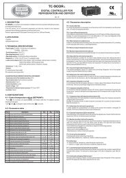
<strong>MT</strong>-<strong>530</strong> <strong>%uper</strong><br />
TEMPERATURE AND HUMIDITY<br />
DIGITAL CONTROLLER WITH<br />
SERIAL COMMUNICATION<br />
Ver.02<br />
<strong>MT</strong>-<strong>530</strong> Super<br />
THERM HUMID<br />
AUX BUZZ<br />
E251415<br />
<strong>MT</strong><strong>530</strong>SP02-01T-12400<br />
1. DESCRIPTION<br />
<strong>MT</strong>-<strong>530</strong> <strong>%uper</strong> is an instrument that indicates and controls the environment temperature and<br />
humidity, indicated for low and average relative air humidity (from 20 to 85%, without condensation) and<br />
temperature of -10 to 70ºC. Its sensors of temperature and humidity are joined in an only bulb, that<br />
reduces the space in wiring of the installation.<br />
®<br />
The instrument has serial communication for connection with the SITRAD via Internet.<br />
Product complies with ULInc. (United States and Canada).<br />
2. APPLICATION<br />
• Humidificators/dehumidificators<br />
• Grains drying<br />
• Laboratories<br />
• Surgical rooms<br />
• Climatized cellars<br />
• Information technology centers<br />
3. TECHNICAL SPECIFICATIONS<br />
- Power Supply: <strong>MT</strong>-<strong>530</strong> Super - 115 or 230 Vac ±10%(50/60 Hz)<br />
<strong>MT</strong>-<strong>530</strong>LSuper - 12 or 24 Vac/dc<br />
- Control Temperature: -10 to 70.0 ºC ±1.5°C (with resolution of 0.1°C)<br />
14 to 158 ºF ±3°F (with resolution of 1°F)<br />
- Control Humidity: 20 to 85%RH ±5%RH (with resolution of 0.1%RH)<br />
- Load current: 5(3)A/250Vac 1/8HP (each output)<br />
- Dimensions: 71 x 28 x 71 mm<br />
- Operation temperature: 0 to 50°C<br />
32 to 122°F<br />
- Operation humidity: 10 to 90% RH (without condensation)<br />
4. CONFIGURATIONS<br />
4.1 - Temperature and humidity adjust (SETPOINTS):<br />
- Press SET for 2 seconds until appears, then release it. The indication and the adjusted<br />
temperature for THERM output will appear.<br />
- Use the keys and to change the value and then press SET to record it.<br />
- Now and adjusted humidity for HUMID output will appear.<br />
- Use the keys and to change the value and then press SET again.<br />
-Then, if the AUX output is set to control (F14 = 0, 1, 2 or 3)it may appear or .<br />
- Use the keys and to change the value for theAUX output and then press SET to record it.<br />
4.2 - Parameters configuration<br />
- Access the function F01 pressing simultaneously the keys and for 2 seconds until appearing<br />
, releasing after that. Soon it will appear , and then press SET (short touch).<br />
- Use the keys and to enter acess code (123) and, when ready press SET to confirm.<br />
- Use the keys and to access the desired function.<br />
-After selecting the function, press<br />
SET (short touch) to visualize the value configured for that function.<br />
- Use the keys and to change the value, and when ready, press SET to memorize the configured<br />
value and return to the menu of functions.<br />
- To leave the menu of functions and return to normal operation, press SET until appear .<br />
4.4 - Parameters description<br />
Fun<br />
Description<br />
Access code: 123 (one hundred and twenty-three)<br />
Thermostat operation mode (THERM output)<br />
Minimum setpoint allowed to the user (thermostat)<br />
Maximum setpoint allowed to the user (thermostat)<br />
Control differential (hysteresis) of the thermostat<br />
Minimum delay to turn the thermostat output on<br />
Humidistat operation mode (HUMID output)<br />
Minimum setpoint allowed to the user (humidistat)<br />
Maximum setpoint allowed to the user (humidistat)<br />
Control differential (hysteresis) of the humidistat<br />
Minimum delay to turn the humidistat output on<br />
Humidity output (time on)<br />
Humidity output (time off)<br />
Auxiliary output operation mode (AUX)<br />
Minimum setpoint allowed to the user (AUX output)<br />
Min.<br />
-99<br />
0 - refrig.<br />
-10.0<br />
-10.0<br />
0<br />
0<br />
0 - dehum.<br />
0<br />
0<br />
0<br />
0<br />
0<br />
0<br />
0<br />
0<br />
CELSIUS<br />
Max.<br />
999<br />
1 - heat<br />
70.0<br />
70.0<br />
20.0<br />
999<br />
1 - hum.<br />
100<br />
100<br />
20.0<br />
999<br />
999<br />
999<br />
10<br />
100<br />
Unit<br />
-<br />
-<br />
°C<br />
°C<br />
°C<br />
seg.<br />
-<br />
%RH<br />
%RH<br />
%RH<br />
sec.<br />
sec.<br />
sec.<br />
-<br />
-<br />
Standard<br />
-<br />
0 - refrig.<br />
-10.0<br />
70.0<br />
1.5<br />
0<br />
1 - hum.<br />
0<br />
100<br />
5<br />
0<br />
5<br />
5<br />
5<br />
0<br />
Min.<br />
-99<br />
0 - refrig.<br />
14<br />
14<br />
0<br />
0<br />
0 - dehum.<br />
0<br />
0<br />
0<br />
0<br />
0<br />
0<br />
0<br />
0<br />
FAHRENHEIT<br />
Max.<br />
999<br />
1 - heat<br />
158<br />
158<br />
36<br />
999<br />
1 - umid.<br />
100<br />
100<br />
20.0<br />
999<br />
999<br />
999<br />
10<br />
100<br />
Unit<br />
-<br />
-<br />
°F<br />
°F<br />
°F<br />
seg.<br />
-<br />
%RH<br />
%RH<br />
%RH<br />
sec.<br />
sec.<br />
sec.<br />
-<br />
-<br />
Standard<br />
-<br />
0 - refrig.<br />
14<br />
158<br />
3<br />
0<br />
1 - hum.<br />
0<br />
100<br />
5<br />
0<br />
5<br />
5<br />
5<br />
0<br />
Maximum setpoint allowed to the user ( AUX output)<br />
Control differential (hysteresis) of the AUX output<br />
Minimum delay to turn the AUX output on<br />
Time base of AUX output timer<br />
AUX output (time on)<br />
AUX output (time off)<br />
Low room temperature alarm<br />
High room temperature alarm<br />
Low room humidity alarm<br />
High room humidity alarm<br />
Minimum delay to turn the AUX output on (alarm mode)<br />
Buzzer operation mode<br />
Acting point of Buzzer by low temperature<br />
Acting point of Buzzer by high temperature<br />
Acting point of Buzzer by low humidity<br />
Acting point of Buzzer by high humidity<br />
Maximum time of the activated THERM output to activate the alarm<br />
Maximum time of the activated HUMID output to activate the alarm<br />
Maximum time of the activated AUX output to activate the alarm<br />
Buzzer time on<br />
Buzzer time off<br />
Inhibition time of Buzzer during electrical supply<br />
Display mode<br />
Temperature display offset<br />
Humidity display offset<br />
Network equipment address RS-485<br />
0<br />
0<br />
0<br />
0<br />
0<br />
0<br />
-10.0<br />
-10.0<br />
0<br />
0<br />
0<br />
0<br />
-10.0<br />
-10.0<br />
0<br />
0<br />
0<br />
0<br />
0<br />
0<br />
0<br />
0<br />
0<br />
-5.0<br />
-20.0<br />
0<br />
100<br />
20.0<br />
999<br />
999<br />
999<br />
999<br />
70.0<br />
70.0<br />
100<br />
100<br />
999<br />
1<br />
70.0<br />
70.0<br />
100<br />
100<br />
999<br />
999<br />
999<br />
999<br />
999<br />
999<br />
2<br />
5.0<br />
20.0<br />
247<br />
-<br />
-<br />
sec.<br />
-<br />
sec.<br />
sec.<br />
°C<br />
°C<br />
%RH<br />
%RH<br />
min.<br />
-<br />
°C<br />
°C<br />
%RH<br />
%RH<br />
min.<br />
min.<br />
min.<br />
sec.<br />
sec.<br />
min.<br />
-<br />
°C<br />
%RH<br />
-<br />
100<br />
5<br />
0<br />
0<br />
5<br />
5<br />
-10.0<br />
70.0<br />
0<br />
100<br />
0<br />
1<br />
-10.0<br />
70.0<br />
0<br />
100<br />
0<br />
0<br />
0<br />
1<br />
1<br />
0<br />
0<br />
0<br />
0<br />
1<br />
0<br />
0<br />
0<br />
0<br />
0<br />
0<br />
14<br />
14<br />
0<br />
0<br />
0<br />
0<br />
14<br />
14<br />
0<br />
0<br />
0<br />
0<br />
0<br />
0<br />
0<br />
0<br />
0<br />
-9<br />
-20.0<br />
0<br />
100<br />
20.0<br />
999<br />
999<br />
999<br />
999<br />
158<br />
158<br />
100<br />
100<br />
999<br />
1<br />
158<br />
158<br />
100<br />
100<br />
999<br />
999<br />
999<br />
999<br />
999<br />
999<br />
2<br />
9<br />
20.0<br />
247<br />
-<br />
-<br />
sec.<br />
-<br />
sec.<br />
sec.<br />
°F<br />
°F<br />
%RH<br />
%RH<br />
min.<br />
-<br />
°F<br />
°F<br />
%RH<br />
%RH<br />
min.<br />
min.<br />
min.<br />
sec.<br />
sec.<br />
min.<br />
-<br />
°F<br />
%RH<br />
-<br />
100<br />
5<br />
0<br />
0<br />
5<br />
5<br />
14<br />
158<br />
0<br />
100<br />
0<br />
1<br />
14<br />
158<br />
0<br />
100<br />
0<br />
0<br />
0<br />
1<br />
1<br />
0<br />
0<br />
0<br />
0<br />
1
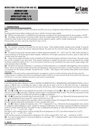
Example: Humidification<br />
Control = 80% RH *Time on = 20 sec<br />
Hysteresis = 5% RH *Time off = 10 sec<br />
When humidity falls to 75% RH (80 - 5), the humidistat output starts to cycle: 20 sec. on - 10 sec. Off<br />
4.4 - Parameters description<br />
F01 -Access code: 123 (one hundred and twenty-three)<br />
It is necessary to change the configuration parameters. To visualize the adjusted parameters, it is not<br />
necessary to insert this access code.<br />
F02 - Thermostat operation mode (THERM output)<br />
Refrigeration<br />
Heating<br />
F03 - Minimum setpoint allowed to the end user (thermostat)<br />
F04 - Maximum setpoint allowed to the end user (thermostat)<br />
It is to prevent that incorrect high or low temperatures be regulated.<br />
F05 - Control differential (hysteresis) of the thermostat<br />
It is the difference of temperature (hysteresis) between ON and OFF the THERM output.<br />
F06 - Minimum delay to turn the thermostat output on<br />
It is the minimum time that the thermostat will keep turned off, it means, the space of time between the<br />
last stop ant the next start.<br />
F07- Humidistat operation mode (HUMID output)<br />
Dehumidification<br />
Humidification<br />
F08 - Minimum setpoint allowed to the user (humidistat)<br />
F09 - Maximum setpoint allowed to the user (humidistat)<br />
Electronic limits whose purpose is prevent that too high or too low setpoint humiditys are regulated.<br />
F10 - Control differential (hysteresis) of the humidistat<br />
It is the difference of humidity (hysteresis) between turn ON and turn OFF the HUMID output.<br />
F11-Minimum delay to turn the humidistat output on<br />
It is the minimum time that the HUMID output will keep turned off, it means, the space of time between<br />
the last stop ant the next start.<br />
F12 - Humidity output (time on)<br />
It allows to adust the time that HUMID output will keep turned on.<br />
F13 - Humidity output (time off)<br />
It allows to adust the time that HUMID output will keep turned off.<br />
Note: F12 and F13 functions control a cyclical program (in seconds) for the humidistat output.<br />
This cyclical program allows that pulverized water has time to transform in relative air humidity.<br />
To disable this function, adjust then with value “00.0”.<br />
F14 -Auxiliary output operation mode (AUX)<br />
Refrigeration<br />
Heating<br />
Dehumidification<br />
Humidification<br />
Intra-range alarm<br />
Extra-range alarm<br />
Independent cyclic timer<br />
Cyclic timer operating only when the temperature reaches the setpoint (THERM output<br />
deactivated)<br />
Cyclic timer operating only when the humidity reaches the setpoint (HUMID output<br />
deactivated)<br />
Cyclic timer operating when the temperature or humidity reaches their setpoint<br />
Cyclic timer operating only when the temperature and humidity reaches their setpoints.<br />
When changing the value of this function the following parameters will be automatically adjusted with<br />
their default values: F15, F16, F17 and setpoint for theAUX output.<br />
F15 - Minimum setpoint allowed to the user (AUX output)<br />
F16 - Maximum setpoint allowed to the user (AUX output)<br />
Electronic limits whose purpose is prevent that too high or too low setpoint values are regulated.<br />
The limits will depend on the operation mode of the output adjusted in F14.<br />
F17 - Control differential (hysteresis) of theAUX output<br />
It is the difference of temperature or humidity (hysteresis) between turn ON and turn OFF the AUX<br />
output. This function depends on the operation mode of the output adjusted in F14.<br />
F18 - Minimum delay to turn theAUX output on<br />
It is the minimum time that the AUX output will keep turned off, it means, the space of time between the<br />
last stop ant the next start.<br />
This time is valid only when AUX output will be configured in the control mode (F14 configured in 0, 1, 2<br />
or 3).<br />
F19 - Time base ofAUX output timer<br />
Allows configuring the on or off time scale forAUX output cyclic timer.<br />
Value Time on (F20) Time off (F21)<br />
Seconds<br />
Minutes<br />
Seconds<br />
Minutes<br />
Seconds<br />
Minutes<br />
Minutes<br />
Seconds<br />
F20 - AUX output (time on)<br />
It allows to adust the time thatAUX output will keep turned on when set to cyclical timer.<br />
F21 - AUX output (time off)<br />
It allows to adust the time thatAUX output will keep turned off when set to cyclical timer.<br />
F22 - Low room temperature alarm<br />
Temperature for activation of the low temperature alarm.<br />
F23 - High room temperature alarm<br />
Temperature for activation of the high temperature alarm.<br />
F24 - Low room humidity alarm<br />
Humidity for activation of the low<br />
humidity alarm.<br />
F25 - High room humidity alarm<br />
Humidity for activation of the high humidity alarm.<br />
F26 - Minimum delay to turn theAUX output on (alarm mode)<br />
It is the minimum time that the AUX output will keep turned off, it means, the space of time between the<br />
last stop ant the next start. This time is valid only when AUX output will be configured in the alarm mode<br />
(F14 configured in 4 or 5).<br />
F27 - Buzzer operation mode<br />
Intra-range alarm<br />
Extra-range alarm<br />
F28 - Acting point of Buzzer by low temperature<br />
It is the inferior value of temperature to the buzzer alarm act as the configured Operation Mode of Buzzer<br />
(F27).<br />
F29 - Acting point of Buzzer by high temperature<br />
It is the superior value of temperature to the buzzer alarm act as the configured Operation Mode of<br />
Buzzer (F27)<br />
F30 - Acting point of Buzzer by low humidity<br />
It is the inferior value of humidity to the buzzer alarm act as the configured Operation Mode of Buzzer<br />
(F27).<br />
F31 - Acting point of Buzzer by high humidity<br />
It is the superior value of humidity to the buzzer alarm act as the configured Operation Mode of Buzzer<br />
(F27).<br />
F32 - Maximum time of the activated THERM output to activate the alarm<br />
Allows configuring the maximum time the output THERM can stay activated without reaching the<br />
setpoint before activating the audible alarm (BUZZER). To deactivate this function, just decrement the<br />
value until the message is displayed.<br />
F33 - Maximum time of the activated HUMID output to activate the alarm<br />
Allows configuring the maximum time the output HUMID can stay activated without reaching the<br />
setpoint before activating the audible alarm (BUZZER). To deactivate this function, just decrement the<br />
value until the message is displayed.<br />
F34 - Maximum time of the activated AUX output to activate the alarm<br />
Allows configuring the maximum time the output AUX can stay activated without reaching the setpoint<br />
before activating the audible alarm (BUZZER). To deactivate this function, just decrement the value until<br />
the message is displayed.<br />
F35 -Buzzer time on<br />
It is the time that the Buzzer will be turned on (cycle on). To turn it off the sonore alarm (Buzzer) adjust the<br />
value “0” to this function.<br />
F36 - Buzzer time off<br />
It is the time that the buzzer will be turned off (cycle off). To turn the sonore alarm (Buzzer) always on,<br />
adjust the value “0” to this function.<br />
F37 - Inhibition time of Buzzer during electrical supply<br />
It is the time were the alarm will kept turned off even if in alarm contitions.<br />
It serves to inhibit the buzzer during the time while the system do not reaches the working control<br />
temperature.<br />
F38 - Display mode<br />
Alternated indication of temperature and humidity<br />
Only indication of temperature<br />
Only indication of humidity<br />
F39 - Temperature display offset<br />
It allows to compensate eventual shunting lines in the reading of temperature proceeding from the<br />
exchange of the sensor or cable lenght alteration.<br />
F40 - Humidity display offset<br />
It allows to compensate eventual shunting lines in the reading of humidity proceeding from the<br />
exchange of the sensor or cable lenght alteration.<br />
F41 - Network equipment address<br />
This is the device address for communication with Sitrad ®<br />
software.<br />
Note: You cannot have two or more devices with the same address in the network.<br />
5. FUNCTIONS WITH FACILITATED ACCESS<br />
5.1- Registers of minimum and maximum temperature and<br />
humidity<br />
Press . Will appear followed for minimum and maximum registered temperatures. After that<br />
will appear and the minimum and maximum registered humidity.<br />
Note: To reset the registers, keep pressed during the visualization of the minimum and maximum<br />
registers until appear .<br />
5.2 - To visualize humidity or temperature<br />
If the F38 function is not in the alternating way of visualization (”0”) it´s possible visualize temperature or<br />
humidity by pressing the key.
OUT 1 OUT 2 OUT 3<br />
OUT 4 ALMR<br />
A<br />
B<br />
A B<br />
Green<br />
A<br />
B<br />
A<br />
B<br />
A B<br />
A<br />
B<br />
PUMP AUX 1 AUX 2<br />
A<br />
B<br />
A B<br />
A<br />
B<br />
A<br />
B<br />
A B<br />
A<br />
B<br />
6. SIGNALLING<br />
Led THERM on - Thermostat output on<br />
Led HUMID on - Humidistat output on<br />
LedAUX on - Auxiliar output on<br />
Led BUZZ on - Buzzer activated<br />
- Irregular temperature sensor<br />
- Irregular humidity sensor<br />
- Invalid configuration parameters;<br />
- In this situation the outputs are turned off;<br />
- Check which parameters have invalid data and correct them to return to normal operation.<br />
7. SELECTION OF THE UNIT (Cº / Fº)<br />
In order to define the unit that the instrument will operate in, enter function “F01” with the access code<br />
“231” and confirm with the SET key. Press the key and the indication will appear. Press<br />
SET to choose between or and confirm.After selecting the unit the message will<br />
appear, and the instrument will return to the function “F01”. Every time that the unit is changed, the<br />
parameters should be reconfigured, since they assume the “standard” values.<br />
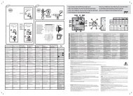
8. WIRING DIAGRAM<br />
1<br />
A<br />
Serial communication<br />
RS-485<br />
9-8<br />
9-7<br />
Yellow<br />
Orangr and<br />
Brown<br />
Red<br />
2 3 4 5 6 7 8 9 10 11 12<br />
B<br />
To the terminal of<br />
the distribution box<br />
<strong>MT</strong>-<strong>530</strong> Super<br />
115V<br />
230V<br />
Temperature and<br />
humidity sensor<br />
Cable: SB56<br />
Violet protector<br />
<strong>MT</strong>-<strong>530</strong>L Super<br />
12V<br />
24V<br />
®<br />
COMMON<br />
230V 115V 0<br />
(24V ) (12V )<br />
Power supply<br />
and relays<br />
common<br />
THERM (NO)<br />
HUMID (NO)<br />
L1<br />
L2<br />
AUX (NO)<br />
L3<br />
Loads<br />
supply<br />
Above specified current<br />
use contactors.<br />
Loads<br />
L1 - Contactor<br />
- Solenoid<br />
L2 - Dehumidificator<br />
- Humidificator<br />
- Contactor<br />
- Solenoid<br />
L3 - Dehumidificator<br />
- Humidificator<br />
- Contactor<br />
- Solenoid<br />
- Alarm<br />
Integrating Controllers, RS-485 Serial Interface and Computer<br />
IMPORTANT<br />
According to the chapters from the IEC60364 standard:<br />
1: Install protectors against over voltage on power supply<br />
2: Sensor cables and computer signals can be together, however not at the same place where power<br />
supply and load wires pass for<br />
3: Install suppresor of transient in parallel to loads to increase the usefull life of the relays<br />
Wiring diagram of suppresors in contactors<br />
Suppresor<br />
A1<br />
A2<br />
A1 e A2 are the<br />
contactor coils.<br />
Wiring diagram of suppresor for direct drive<br />
Suppresor<br />
Load<br />
For direct activation the maximum<br />
specified current should be taken<br />
into consideration.<br />
Note: The sensor cable lenght can be increased by the user until 200 meters using 4 x 0,20mm² cable.<br />
ENVIRONMENTAL INFORMATION<br />
Package:<br />
The packages material are 100% recyclable. Just dispose it through specialized<br />
recyclers.<br />
Products:<br />
The electro components of Full Gauge controllers can be recycled or reused if it is<br />
disassembled for specialized companies.<br />
Disposal:<br />
Do not burn or throw in domestic garbage the controllers which have reached the end-oflife.<br />
Observe the respectively law in your region concerning the environmental<br />
responsible manner of dispose its devices. In case of any doubts, contact Full Gauge<br />
controls for assistance.<br />
PROTECTIVE VINYL:<br />
This adhesive vinyl (included inside the packing) protects the instruments against<br />
water drippings, as in commercial refrigerators, for example. Do the application after<br />
finishing the electrical connections.<br />
A<br />
B<br />
A B<br />
A<br />
B<br />
RS-485 Network<br />
Serial interface<br />
RS-485<br />
Full Gauge<br />
RS-485 Network<br />
Remove the protective paper<br />
and apply the vinyl on the entire<br />
superior part of the device,<br />
folding the flaps as indicated by<br />
the arrows.<br />
Instrument<br />
PCT-4 0R plus<br />
B<br />
A<br />
B<br />
A<br />
B<br />
A<br />
External<br />
mesh<br />
terminal<br />
grounded<br />
Distribution Box<br />
Used to connect more than one instrument to the Interface. The wire's connections must<br />
be made in agreement with the following rules: terminal A of the instrument connects to<br />
the terminal Aof the distribution box, that must be connected with the terminal Aof the<br />
Interface. Repeat the action for terminals B and , being the cable shield.<br />
The terminal of distribution box must be connected to the respective terminals of<br />
each instrument.<br />
MICROSOL I plus<br />
MOD 64<br />
RS-485 Serial Interface<br />
Device used to establish the<br />
connection Full Gauge Controls’<br />
®<br />
instruments with the Sitrad .<br />
A<br />
B<br />
Dimension of the clipping<br />
for setting of the instrument<br />
in panel<br />
72 mm<br />
29 mm