Series PAVC Variable Volume, Piston Pumps
Series PAVC Variable Volume, Piston Pumps
Series PAVC Variable Volume, Piston Pumps

Create successful ePaper yourself
Turn your PDF publications into a flip-book with our unique Google optimized e-Paper software.
Hydraulics<br />
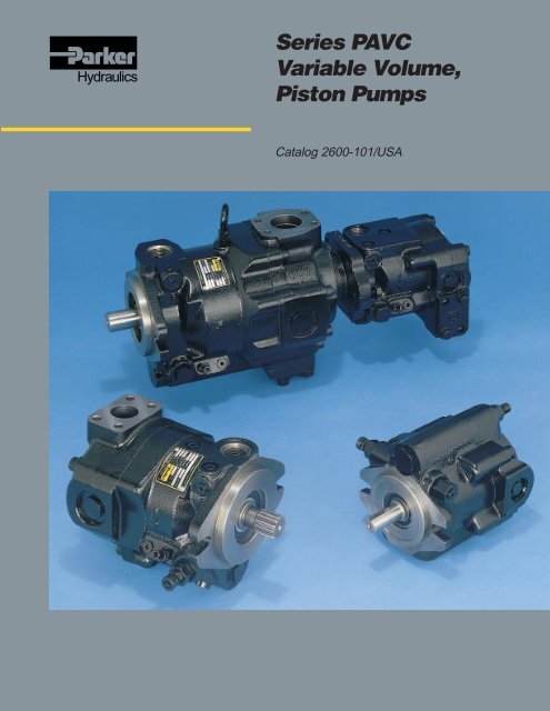
<strong>Series</strong> <strong>PAVC</strong><br />
<strong>Variable</strong> <strong>Volume</strong>,<br />
<strong>Piston</strong> <strong>Pumps</strong><br />
Catalog 2600-101/USA
Introduction<br />
<strong>Variable</strong> <strong>Volume</strong> <strong>Piston</strong> <strong>Pumps</strong><br />
<strong>Series</strong> <strong>PAVC</strong><br />
Quick Reference Data Chart<br />
Pump<br />
Model<br />
Displacement<br />
CM 3 /REV<br />
(IN 3 /REV)<br />
Pump Delivery *Approx. Noise Levels dB(A) Horsepower At<br />
Pressure<br />
@ 300 PSI (21 bar) @ Full Flow 1800 RPM (1200 RPM)<br />
Operating<br />
1800 RPM, and At<br />
PSI (bar)<br />
in GPM (LPM)<br />
Speed RPM<br />
500 PSI 1000 PSI 2000 PSI 3000 PSI Maximum Pressure Continuous<br />
(Maximum)<br />
1200 RPM 1800 RPM (34 bar) (69 bar) (138 bar) (207 bar) & Displacement (Maximum)<br />
<strong>PAVC</strong>33 33 (2.0) 10.4 (39.4) 15.6 (59.0) 75 (69) 76 (72) 78 (75) 79 (77) 28.5 3000 3000 (207)<br />
<strong>PAVC</strong>38 38 (2.3) 11.9 (45.0) 17.9 (67.8) 75 (69) 76 (72) 78 (75) 79 (77) 33.0 3000 3000 (207)<br />
<strong>PAVC</strong>65 65 (4.0) 20.8 (78.7) 31.2 (118.1) 77 (75) 78 (76) 80 (78) 81 (79) 56.5 3000 3000 (207)<br />
<strong>PAVC</strong>100 100 (6.1) 31.6 (119.6) 47.5 (179.8) 83 (77) 82 (78) 82 (79) 85 (80) 95.5 2600 3000 (207)<br />
*Since many variables such as mounting, tank style, plant layout, etc., effect noise levels, it cannot be assumed that the above readings will be equal to those<br />
in the field. The above values are for guidance in selecting the proper pump. Noise levels are A-weighted, mean sound pressure levels at 1 meter from the<br />
pump, measured and recorded in accordance with applicable ISO and NFPA standards.<br />
Hydraulics<br />
1<br />
Parker Hannifin Corporation<br />
Hydraulic Pump/Motor Division<br />
Otsego, MI 49078
Introduction<br />
<strong>Variable</strong> <strong>Volume</strong> <strong>Piston</strong> <strong>Pumps</strong><br />
<strong>Series</strong> <strong>PAVC</strong><br />
PUMP<br />
HOUSING<br />
REPLACEABLE<br />
PORT PLATE<br />
HYDRODYNAMIC<br />
BEARING<br />
REAR<br />
COVER<br />
SEALED<br />
BEARING<br />
SHAFT<br />
SEAL<br />
CYLINDER<br />
BARREL<br />
SERVO<br />
PISTON<br />
Features<br />
• High Strength Cast-Iron Housing<br />
• Built-In Supercharger<br />
• High Speed Capability - 3000 RPM<br />
(2600 RPM <strong>PAVC</strong>100)<br />
• Sealed Shaft Bearing<br />
• Two Piece Design For Ease of Service<br />
• Cartridge Type Controls - Field Changeable<br />
• Replaceable Bronze Clad Port Plate<br />
• Airbleed Standard for Quick Priming<br />
• Hydrodynamic Cylinder Barrel Bearing<br />
• Thru-Shaft (<strong>PAVC</strong>100 Only)<br />
• Full Pressure Rating On Water Glycol Fluids<br />
• Pump Case and Shaft Seal - See Inlet<br />
Pressure Only<br />
• Filter And/Or Cool Drain Line (100 PSI Max.)<br />
Controls<br />
• Pressure Compensation<br />
• Load Sensing<br />
• Horsepower (Torque) Limiting<br />
• Horsepower and Load Sensing<br />
• Remote Pressure Compensation<br />
• Adjustable Maximum <strong>Volume</strong> Stop<br />
• Electrohydraulic Pressure<br />
• Electrohydraulic Flow & Pressure (Servo Control)<br />
• Low Pressure Standby<br />
Hydraulics<br />
2<br />
Parker Hannifin Corporation<br />
Hydraulic Pump/Motor Division<br />
Otsego, MI 49078
<strong>Variable</strong> <strong>Volume</strong> <strong>Piston</strong> <strong>Pumps</strong><br />
Introduction <strong>Series</strong> <strong>PAVC</strong> 33/38/65/100<br />
General Description<br />
All control is achieved by the proper positioning of the<br />
swash plate. This is achieved by a servo piston acting<br />
on one end of the swash plate working against the<br />
combined effect of the off-setting forces of the pistons<br />
and centering spring on the other end. The control<br />
spool acts as a metering valve which varies the<br />
pressure behind the servo piston.<br />
As shown in Figure 1, the amount of flow produced by<br />
the Parker <strong>Piston</strong> Pump is dependent upon the length<br />
of stroke of the pumping pistons. This length of stroke,<br />
in turn, is determined by the position of the swash<br />
plate. Maximum flow is achieved at an angle of 17°.<br />
The rotating piston barrel, driven by the prime mover,<br />
moves the pistons in a circular path and the piston<br />
slippers are supported hydrostatically against the face<br />
of the swash plate. When the swash plate is in a<br />
vertical position, perpendicular to the centerline of<br />
the piston barrel, there is no piston stroke and<br />
consequently no fluid displacement. When the swash<br />
plate is positioned at an angle, the pistons are forced<br />
in and out of the barrel and fluid displacement takes<br />
place. The greater the angle of the swash plate, the<br />
greater the piston stroke.<br />
The centerline of the pumping piston assembly is offset<br />
from the centerline of the swash plate. Therefore, as<br />
shown on the accompanying Figure 1A, the pistons’<br />
effective summation force tends to destroke the swash<br />
plate to a vertical (neutral) position. This destroking<br />
force is balanced as the swash plate is angled by the<br />
force of the servo piston.<br />
ROTATING<br />
PISTON<br />
BARREL<br />
PUMPING<br />
PISTON<br />
OUTPUT<br />
SUMMATION OF<br />
PISTON FORCES<br />
DRIVE<br />
SHAFT<br />
INPUT<br />
OIL FLOW<br />
SERVO PISTON<br />
SWASH<br />
PLATE<br />
FIGURE 1. Pumping Action FIGURE 1A.<br />
Hydraulics<br />
3<br />
Parker Hannifin Corporation<br />
Hydraulic Pump/Motor Division<br />
Otsego, MI 49078
<strong>Variable</strong> <strong>Volume</strong> <strong>Piston</strong> <strong>Pumps</strong><br />
Control Options <strong>Series</strong> <strong>PAVC</strong> 33/38/65/100<br />
Pressure Compensated Control<br />
Swash plate angle controls the output flow of the pump.<br />
Swash plate angle is controlled by the force generated<br />
against the swash plate by the pumping pistons and<br />
by the force of the servo piston. The force of the servo<br />
piston is greater than the force of the pumping pistons<br />
when both are at the same pressure.<br />
By means of internal porting, pressure is connected<br />
from the output port to the servo piston via orifice (E),<br />
and to the control spool via passage (D). Also pressure<br />
is applied to the control spool chamber thru orifice<br />
(F). As long as the pressures at both ends of the<br />
control spool remain equal, the spool will remain offset<br />
upward, due to the added force of the spring.<br />
When pressure reaches the setting of the compensator<br />
control, the dart leaves its seat causing the pressure<br />
in the spool chamber to be reduced. The spool now<br />
moves downward causing pressure in the servo piston<br />
cavity to vent via port “A”. The reduced pressure at<br />
the servo piston allows the servo piston to move to<br />
the right. This movement reduces the angle of the<br />
swash plate and thereby reduces the pumps output<br />
flow.<br />
As pump pressure on the control spool drops below<br />
pressure and spring force in the spool chamber, the<br />
control spool moves upward to maintain an equilibrium<br />
on both sides of the spool. If pump pressure falls<br />
INLET<br />
CONTROL OPTION - ‘OMIT’<br />
SWASHPLATE<br />
BARREL<br />
PISTON<br />
AIRBLEED VALVE<br />
ASSEMBLY<br />
D<br />
below compensator control setting, the control spool<br />
moves up, bringing the pump to maximum<br />
displacement.<br />
∆P Adjustment of <strong>PAVC</strong> <strong>Pumps</strong><br />
PROCEDURE:<br />
a. Standard Pressure Compensated Pump<br />
<strong>Pumps</strong> are shipped from factory with a differential<br />
pressure of approximately 150 PSI (10 bar) on <strong>PAVC</strong><br />
33/38/65, <strong>PAVC</strong> 100 is 300 PSI (21 bar) at 50% of<br />
maximum swash angle. Differential pressure will<br />
not normally change through the life of the pump. If<br />
this control has been tampered with, a close<br />
approximation of the correct setting can be made<br />
as follows:<br />
Dead head the pump (no flow) with a 0-3000 PSI<br />
(0-207 bar) gauge in the OUTLET (not the low<br />
signal “B” port), back the pressure compensator<br />
adjustment out (full counterclockwise).<br />
The gauge should read between 325-375 PSI<br />
(22-26 bar) <strong>PAVC</strong> 33, 38 & 65, 500-575 PSI<br />
(34-40 bar) <strong>PAVC</strong> 100. If the gauge reads different<br />
than this, turn the differential adjustment knob<br />
(Differential Option 4) or add/remove shims (Omit<br />
Option) until correct PSI figure is reached.<br />
OUTLET<br />
FLOW<br />
(AT CONSTANT SPEED)<br />
PRESSURE<br />
PISTON<br />
SERVO PISTON<br />
E<br />
CONTROL<br />
SPOOL AND<br />
SLEEVE<br />
CONTROL DRAIN<br />
PORT “A”<br />
F<br />
CONTROL SPOOL<br />
SPRING CHAMBER<br />
PRESSURE<br />
COMPENSATOR<br />
ADJUSTMENT<br />
DIFFERENTIAL<br />
ADJUSTMENT<br />
Hydraulics<br />
4<br />
Parker Hannifin Corporation<br />
Hydraulic Pump/Motor Division<br />
Otsego, MI 49078
<strong>Variable</strong> <strong>Volume</strong> <strong>Piston</strong> <strong>Pumps</strong><br />
Control Options <strong>Series</strong> <strong>PAVC</strong> 33/38/65/100<br />
Remote Pressure Control<br />
Control Type (M)<br />
Remote control of the <strong>PAVC</strong> output pressure can be<br />
achieved by controlling the pressure in the low signal<br />
“B” port when the pump is set up for Control Type<br />
(M). A manual, hydraulically piloted, electrical or<br />
electro-proportionally controlled pressure control<br />
device is installed in the line from the low signal “B”<br />
port to tank. The pump will then maintain pressure<br />
approximately equal to the pressure in the “B” port<br />
plus the pump differential setting.<br />
Low Pressure Standby<br />
This option can be used as an alternative to the load<br />
sensing option (A) to achieve low pressure standby.<br />
Minimum standby pressure is somewhat higher than<br />
that achieved using option (A). In the compensating<br />
mode there is approximately .3 GPM (1.14 LPM) flow<br />
from the low signal “B” port in addition to .9 GPM (3.4<br />
LPM) flow from the control drain port “A”.<br />
concept, multiple, remotely piloted relief valves<br />
plumbed in parallel in the “B” port line can yield<br />
multiple, sequential pressure settings.<br />
Electrohydraulic Pressure & Flow Control<br />
A proportional pressure control valve can be used in<br />
place of relief valves to give variable pressure control<br />
proportional to an electrical input signal to the valve.<br />
By combining this arrangement with a swash plate<br />
position sensing device, amplifier, and logic circuit,<br />
servo control of pressure and/or flow is achieved.<br />
NOTE: In most systems, a load equivalent to the<br />
minimum operating pressure of the pump cannot be<br />
guaranteed. Because of this, a sequence valve is<br />
required in the discharge line to maintain servo flow<br />
control. Please refer to ordering information section<br />
for servo components.<br />
Multiple Pressure Standby<br />
If the pressure level in the low signal “B” port is limited<br />
by a relief valve, as the desired pump outlet pressure<br />
is reached, the relief valve in the “B” port will allow the<br />
pump to standby at a preset pressure. Adding to this<br />
CONTROL OPTION - ‘M’<br />
SWASHPLATE<br />
AIRBLEED VALVE<br />
ASSEMBLY<br />
FLOW<br />
(AT CONSTANT SPEED)<br />
PRESSURE<br />
PISTON<br />
OUTLET<br />
INLET<br />
BARREL<br />
D<br />
PISTON<br />
SERVO PISTON<br />
E<br />
CONTROL<br />
SPOOL AND<br />
SLEEVE<br />
PORT “B”<br />
F<br />
CONTROL DRAIN<br />
PORT “A”<br />
CONTROL SPOOL<br />
SPRING CHAMBER<br />
PRESSURE<br />
COMPENSATOR<br />
ADJUSTMENT<br />
DIFFERENTIAL<br />
ADJUSTMENT<br />
Hydraulics<br />
5<br />
Parker Hannifin Corporation<br />
Hydraulic Pump/Motor Division<br />
Otsego, MI 49078
<strong>Variable</strong> <strong>Volume</strong> <strong>Piston</strong> <strong>Pumps</strong><br />
Control Options <strong>Series</strong> <strong>PAVC</strong> 33/38/65/100<br />
Pressure & Flow Control (Load Sensing)<br />
Control Type (A)<br />
Flow control is achieved by placing an orifice (fixed or<br />
adjustable) in the pump outlet port. The pressure drop<br />
(∆P) across this flow control is the governing signal<br />
that controls the pump’s output, as explained below.<br />
Whenever the pressure drop at the flow control<br />
increases (indicating an increase in output flow), the<br />
pump attempts to compensate by decreasing the<br />
output flow. It does this by sensing the lower pressure<br />
on the downstream side of the flow control via line<br />
(C), which is balanced against the pump pressure via<br />
passage (D), on the control spool. The control spool<br />
is forced down against the control spool spring by<br />
differential pressure. This vents the servo piston cavity,<br />
destroking the pump to a point where the set pressure<br />
drop across the orifice is maintained and the flow is<br />
obtained.<br />
The converse of this is also true whenever the pressure<br />
drop decreases (indicating a decrease in output flow).<br />
In this case, the control spool is forced up. This<br />
increases pump displacement in an attempt to maintain<br />
the predetermined pressure drop or constant flow.<br />
It should be noted that the pump is still pressure<br />
compensated and destrokes at the selected pressure<br />
setting. The pressure compensator control will override<br />
the flow control whenever the pressure compensator<br />
control setting is reached.<br />
SWASHPLATE<br />
PISTON<br />
CONTROL OPTION - ‘A’<br />
AIRBLEED VALVE<br />
ASSEMBLY<br />
Low Pressure Standby<br />
This arrangement can also be used to provide low<br />
pressure standby by venting the “B” port through a<br />
simple on/off valve suitable for flows of 1-2 GPM (3.8-<br />
7.6 LPM). When flow or pressure is required, this valve<br />
is closed allowing system pressure to build behind<br />
the control spool and bringing the pump on-stroke.<br />
Load Sensing<br />
If, instead of measuring the pressure drop across the<br />
orifice in the pump outlet port, it is measured<br />
downstream of a directional control valve, a constant<br />
pressure drop will be maintained across the valve<br />
spool. This results in a constant flow for any given<br />
opening of the directional control valve regardless of<br />
the work load downstream or the operating speed of<br />
the pump.<br />
The pump “senses” the amount of pressure necessary<br />
to move the load and adjusts output flow to match the<br />
valve opening selected and pressure to overcome the<br />
load plus the preset ∆P across the valve spool.<br />
The benefits of this arrangement are that excellent,<br />
repeatable flow characteristics are achieved, and<br />
considerable energy savings are realized while<br />
metering, compared to using a straight pressure<br />
compensated system.<br />
FLOW CONTROL<br />
ADJUSTMENT<br />
SYSTEM PRESSURE<br />
FLOW<br />
(AT CONSTANT SPEED)<br />
PRESSURE<br />
INLET<br />
BARREL<br />
D<br />
PISTON<br />
SERVO PISTON<br />
E<br />
CONTROL<br />
SPOOL<br />
AND<br />
SLEEVE<br />
C<br />
SIGNAL LINE<br />
F<br />
PORT “B”<br />
CONTROL DRAIN<br />
PORT “A”<br />
CONTROL SPOOL<br />
SPRING CHAMBER<br />
PRESSURE<br />
COMPENSATOR<br />
ADJUSTMENT<br />
DIFFERENTIAL<br />
ADJUSTMENT<br />
Hydraulics<br />
6<br />
Parker Hannifin Corporation<br />
Hydraulic Pump/Motor Division<br />
Otsego, MI 49078
<strong>Variable</strong> <strong>Volume</strong> <strong>Piston</strong> <strong>Pumps</strong><br />
Control Options <strong>Series</strong> <strong>PAVC</strong> 33/38/65/100<br />
Pressure & Horsepower Control<br />
Control Type (H)<br />
The horsepower control is sensitive to the position of<br />
the servo piston. When the servo piston is to the right,<br />
the swash plate causes low flow and the power control<br />
piston develops maximum spring pressure on its<br />
companion poppet (mechanical feedback). When the<br />
servo piston is left and the flow is high, the power<br />
control piston reduces spring pressure on the poppet.<br />
This allows it to open under less pressure in the control<br />
spool chamber, thereby venting some of the pressure<br />
in the control spool chamber. As with the operation of<br />
the pressure compensator control, this allows the<br />
control spool to move downward, venting the servo<br />
piston cavity and causing the servo piston to move to<br />
the right. This reduces output flow and thereby power.<br />
As indicated in the pictorial drawing, pressure in<br />
the control spool chamber is affected by both the<br />
pressure compensator control and the power control.<br />
The resultant pressure in this chamber is a function of<br />
the set points of these two controls. Both set points<br />
are adjustable.<br />
O S O CO S O CO O<br />
CONTROL OPTION - ‘H’<br />
SWASHPLATE<br />
AIRBLEED VALVE<br />
ASSEMBLY<br />
FLOW<br />
(AT CONSTANT SPEED)<br />
PRESSURE<br />
PISTON<br />
OUTLET<br />
INLET<br />
BARREL<br />
D<br />
PISTON<br />
POWER<br />
CONTROL<br />
PISTON<br />
SERVO PISTON<br />
E<br />
CONTROL<br />
SPOOL AND<br />
SLEEVE<br />
CONTROL DRAIN<br />
PORT “A”<br />
F<br />
CONTROL SPOOL<br />
SPRING CHAMBER<br />
HORSEPOWER<br />
(TORQUE)<br />
ADJUSTMENT<br />
PRESSURE<br />
COMPENSATOR<br />
ADJUSTMENT<br />
DIFFERENTIAL<br />
ADJUSTMENT<br />
Hydraulics<br />
7<br />
Parker Hannifin Corporation<br />
Hydraulic Pump/Motor Division<br />
Otsego, MI 49078
Technical Information<br />
<strong>Variable</strong> <strong>Volume</strong> <strong>Piston</strong> <strong>Pumps</strong><br />
How to read horsepower control curve data<br />
FLOW<br />
Outlet Flow (GPM)<br />
HORSEPOWER<br />
16<br />
14<br />
12<br />
10<br />
8<br />
6<br />
4<br />
2<br />
0<br />
1800 RPM<br />
A<br />
A<br />
0 1000 2000 3000<br />
Pressure - PSI<br />
B<br />
B<br />
C<br />
C<br />
D<br />
D<br />
E<br />
E<br />
25<br />
20<br />
15<br />
10<br />
5<br />
0<br />
Horsepower HP<br />
800<br />
600<br />
400<br />
200<br />
0<br />
Input Torque (In.-Lb.)<br />
1. Horsepower “A” curve corresponds to flow “A” curve. This represents<br />
a particular setting of the torque control.<br />
2. With this setting the maximum horsepower required will be as shown<br />
at the apex (maximum point) of the horsepower curve.<br />
3. The flow at this setting will follow the flow vs. pressure curve shown.<br />
4. Example – 1800 RPM, curve labeled “C”:<br />
A. Flow will follow curve “C” and pump will deadhead at 2750 PSI.<br />
B. Full flow will not be realized above 1200 PSI.<br />
C. Flow at 1500 PSI will be approximately 12.7 GPM.<br />
D. Maximum horsepower (15 HP) occurs at approximately 1700 PSI.<br />
5. Torque values are shown to correspond to horsepowers at speed shown.<br />
Hydraulics<br />
8<br />
Parker Hannifin Corporation<br />
Hydraulic Pump/Motor Division<br />
Otsego, MI 49078
<strong>Variable</strong> <strong>Volume</strong> <strong>Piston</strong> <strong>Pumps</strong><br />
Control Options <strong>Series</strong> <strong>PAVC</strong> 33/38/65/100<br />
Pressure, Horsepower & Flow Control<br />
Control Type (C)<br />
In addition to the three control configurations just<br />
discussed, it is possible to combine all three control<br />
devices in one pump. In this mode, the position of the<br />
control spool is a function of the actions of the pressure<br />
compensator adjustment, horsepower adjustment, and<br />
flow control.<br />
CONTROL OPTION - ‘C’<br />
FLOW<br />
(AT CONSTANT SPEED)<br />
PRESSURE<br />
SWASHPLATE<br />
AIRBLEED VALVE<br />
ASSEMBLY<br />
FLOW CONTROL<br />
ADJUSTMENT<br />
PISTON<br />
SYSTEM PRESSURE<br />
INLET<br />
BARREL<br />
D<br />
PISTON<br />
POWER<br />
CONTROL<br />
PISTON<br />
SERVO PISTON<br />
CONTROL DRAIN<br />
PORT “A”<br />
E<br />
CONTROL<br />
SPOOL<br />
AND<br />
SLEEVE<br />
SIGNAL LINE<br />
F<br />
CONTROL SPOOL<br />
SPRING CHAMBER<br />
C<br />
PORT “B”<br />
HORSEPOWER<br />
(TORQUE)<br />
ADJUSTMENT<br />
PRESSURE<br />
COMPENSATOR<br />
ADJUSTMENT<br />
DIFFERENTIAL<br />
ADJUSTMENT<br />
Hydraulics<br />
9<br />
Parker Hannifin Corporation<br />
Hydraulic Pump/Motor Division<br />
Otsego, MI 49078