Series 2H Heavy Duty Hydraulic Cylinders
Series 2H Heavy Duty Hydraulic Cylinders
Series 2H Heavy Duty Hydraulic Cylinders

Create successful ePaper yourself
Turn your PDF publications into a flip-book with our unique Google optimized e-Paper software.
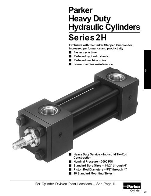
Parker<br />
<strong>Heavy</strong> <strong>Duty</strong><br />
<strong>Hydraulic</strong> <strong>Cylinders</strong><br />
<strong>Series</strong> <strong>2H</strong><br />
Exclusive with the Parker Stepped Cushion for<br />
increased performance and productivity<br />
■ Faster cycle time<br />
■ Reduced hydraulic shock<br />
■ Reduced machine noise<br />
■ Lower machine maintenance<br />
B<br />
■ <strong>Heavy</strong> <strong>Duty</strong> Service – Industrial Tie-Rod<br />
Construction<br />
■ Nominal Pressure – 3000 PSI<br />
■ Standard Bore Sizes – 1-1/2" through 6"<br />
■ Piston Rod Diameters – 5/8" through 4"<br />
■ 18 Standard Mounting Styles<br />
For Cylinder Division Plant Locations – See Page II.<br />
Cylinder<br />
39
The heavy-duty hydraulic<br />
cylinder with features<br />
only Parker can promise<br />
– and deliver!<br />
<strong>Series</strong> <strong>2H</strong> cylinders keep on performing like you<br />
expect from Parker — producing more power per<br />
pound, more power per dollar — over millions of<br />
trouble-free cycles. Everything you need for reliable<br />
3,000 psi performance. Patented “Jewel” rod gland<br />
for longer life and lower operating costs. Chromeplated,<br />
case hardened piston rods. Rod end studs of<br />
high yield-strength steel, with rolled threads for added<br />
strength. Tie rods with rolled threads and steel nuts.<br />
Floating cushions with float-check action and positive<br />
metal-to-metal seal. And every Parker cylinder is<br />
individually tested before it leaves our plant.<br />
For additional information – call your local Parker Cylinder Distributor.<br />
40
<strong>Series</strong> <strong>2H</strong><br />
<strong>Heavy</strong> <strong>Duty</strong> <strong>Hydraulic</strong> <strong>Cylinders</strong><br />
Standard Specifications<br />
• <strong>Heavy</strong> <strong>Duty</strong> Service – NFPA specifications and<br />
ANSI B93.15-1981 mounting dimension standards<br />
• Standard Construction – Square Head – Tie Rod Design<br />
• Nominal Pressure – 3000 P.S.I.*<br />
• Standard Fluid – <strong>Hydraulic</strong> Oil<br />
• Standard Temperature – -10 deg F to +165 deg F**<br />
• Bore Sizes – 1 1 /2" through 6" (Larger sizes available)<br />
Tie Rods Extended Head End<br />
Style TB<br />
1 1 /2 -6"<br />
Page 44<br />
Available Mounting Styles<br />
Tie Rods Extended Cap End<br />
Style TC<br />
1 1 /2 -6"<br />
Page 44<br />
Tie Rods Extended Both Ends<br />
Specifications/<br />
Mountings<br />
• Piston Rod Diameter – 5 /8" through 4"<br />
• Mounting Styles – 18 standard styles at various application ratings<br />
• Strokes – Available in any practical stroke length<br />
• Cushions – Optional at either end or both ends of stroke.<br />
“Float Check” at cap end.<br />
• Rod Ends – Three Standard Choices – Specials to Order<br />
*If hydraulic operating pressure exceeds 3000 P.S.I., send application data for engineering<br />
evaluation and recommendation. See section C, page 84 for actual design factors.<br />
In line with our policy of continuing product improvement, specifications in this catalog<br />
** See section C, page 83 for higher temperature service.<br />
are subject to change.<br />
Note: <strong>Series</strong> <strong>2H</strong> <strong>Hydraulic</strong> <strong>Cylinders</strong> fully meet N.F.P.A. Standards and ANSI Standard B93.15-1981 for Mounting Dimensions for Square Head Industrial Fluid Power <strong>Cylinders</strong>.<br />
Style TD<br />
1 1 /2 -6"<br />
Page 44<br />
Head Rectangular Flange<br />
Style J<br />
1 1 /2 -6"<br />
Page 46<br />
B<br />
(NFPA MX3)<br />
(NFPA MX2)<br />
(NFPA MX1)<br />
(NFPA MF1)<br />
Head Square Flange Head Rectangular Cap Rectangular Flange Cap Square Flange<br />
Style JB<br />
1 1 /2 -6"<br />
Page 46<br />
Style JJ<br />
1 1 /2 -6"<br />
Page 46<br />
Style H<br />
1 1 /2 -6"<br />
Page 48<br />
Style HB<br />
1 1 /2 -6"<br />
Page 48<br />
(NFPA MF5)<br />
(NFPA ME5)<br />
(NFPA MF2)<br />
(NFPA MF6)<br />
Cap Rectangular Side Lug Centerline Lugs Side Tapped<br />
Style HH<br />
1 1 /2 -6"<br />
Page 48<br />
Style C<br />
1 1 /2 -6"<br />
Page 50<br />
Style E<br />
1 1 /2 -6"<br />
Page 50<br />
Style F<br />
1 1 /2 -6"<br />
Page 50<br />
(NFPA ME6)<br />
(NFPA MS2)<br />
(NFPA MS3)<br />
(NFPA MS4)<br />
Side End Angles Side End Lugs Cap Fixed Clevis<br />
Style CB<br />
1 1 /2 -6"<br />
Page 52<br />
Style G<br />
1 1 /2 -6"<br />
Page 52<br />
Style BB<br />
1 1 /2 -6"<br />
Page 52<br />
Head Trunnion<br />
Style D<br />
1 1 /2 -6"<br />
Page 54<br />
(NFPA MS1)<br />
(NFPA MS7)<br />
(NFPA MP1)<br />
Cap Trunnion Intermediate Fixed Trunnion Spherical Bearing<br />
Style DB<br />
1 1 /2 -6"<br />
Page 54<br />
Style DD<br />
1 1 /2 -6"<br />
Page 54<br />
Style SB<br />
1 1 /2 -6"<br />
Page 56<br />
(NFPA MT1)<br />
Double Rod <strong>Cylinders</strong><br />
Style KT Shown<br />
1 1 /2-6"<br />
(NFPA MT2)<br />
(NFPA MT4)<br />
Most of the above<br />
illustrated mounting<br />
styles are available in<br />
double rod cylinders. See Catalog Page 58.<br />
For Cylinder Division Plant Locations – See Page II.<br />
Cylinder<br />
41
The inside story on why<br />
series <strong>2H</strong> is your best choice in<br />
heavy duty hydraulic cylinders<br />
Primary Seal – New TS-2000 Rod Seal is a<br />
proven leakproof design – completely selfcompensating<br />
and self-relieving to withstand<br />
variations and conform to mechanical deflection<br />
that may occur.<br />
Piston Rod Stud –<br />
Furnished on 2" diameter rods<br />
and smaller when standard<br />
style #4 rod end threads are<br />
required or on 1 3 /8" diameter<br />
rods and smaller when style<br />
#8 threads are required. Also<br />
available in 2 times the<br />
catalog “A” dimension length.<br />
Studs have rolled threads and<br />
are made from high strength<br />
steel. Anaerobic adhesive is<br />
used to permanently lock the<br />
stud to the piston rod.<br />
“Jewel” Rod Gland<br />
Assembly –<br />
Externally removable<br />
without cylinder<br />
disassembly. Long<br />
bearing surface is<br />
inboard of the seals,<br />
assuring positive<br />
lubrication from<br />
within the cylinder.<br />
An “O” ring is used<br />
as a seal between<br />
gland and head,<br />
and also serves as<br />
a prevailing torquetype<br />
lock.<br />
Secondary Seal –<br />
Double-Service Wiperseal ®<br />
(Hannifin Patent #2907596) –<br />
wipes clean any oil film<br />
adhering to the rod on the<br />
extend stroke and cleans<br />
the rod on the return stroke.<br />
Stepped Cushions<br />
Sleeve Design Spear Design<br />
High Strength Tie<br />
Rods – Made from<br />
100,000 psi minimum<br />
yield steel with rolled<br />
threads for added<br />
strength.<br />
Steel Head – Bored and<br />
grooved to provide concentricity<br />
for mating parts.<br />
Ports – S.A.E. “O” ring ports<br />
are standard.<br />
End Seals – Pressure-actuated<br />
cylinder body-to-head and cap<br />
“O” rings.<br />
The Cylinder Body –<br />
<strong>Heavy</strong>-wall steel<br />
tubing, honed to a<br />
micro finish bore.<br />
Adjustable Floating Stepped Cushions – For maximum<br />
performance – economical and flexible for even the most demanding<br />
applications – provides superior performance in reducing shock.<br />
Cushions are optional and can be supplied at head end, cap end, or<br />
both ends without change in envelope or mounting dimensions.<br />
Parker's New, Exclusive<br />
Stepped floating cushions<br />
combine the best features of<br />
known cushion technology.<br />
Deceleration devices or built-in “cushions” are optional and can be<br />
supplied at head end, cap end, or both ends without change in<br />
envelope or mounting dimensions. Parker cylinder cushions are a<br />
stepped design and combine the best features of known cushion<br />
technology.<br />
Standard straight or tapered cushions have been used in industrial<br />
cylinders over a very broad range of applications. Parker research<br />
has found that both designs have their limitations.<br />
As a result, Parker has taken a new approach in cushioning of<br />
industrial hydraulic cylinders and for specific load and velocity<br />
conditions have been able to obtain deceleration curves that come<br />
very close to the ideal. The success lies in a stepped sleeve or<br />
spear concept where the steps are calculated to approximate<br />
theoretical orifice areas curves.<br />
In the cushion performance chart, pressure traces show the<br />
results of typical orifice flow conditions. Tests of a three-step<br />
sleeve or spear show three pressure pulses coinciding with the<br />
steps. The deceleration cushion plunger curves shape comes very<br />
close to being theoretical, with the exception of the last 1 /2 inch of<br />
travel. This is a constant shape in order to have some flexibility in<br />
application. The stepped cushion design shows reduced pressure<br />
peaks for most load and speed conditions, with comparable<br />
reduction of objectionable stopping forces being transmitted to the<br />
load and the support structure.<br />
All Parker Hannifin<br />
cushions are<br />
adjustable.<br />
The <strong>Series</strong> <strong>2H</strong><br />
cylinder design<br />
incorporates the<br />
longest cushion<br />
sleeve and cushion<br />
spear that can be<br />
provided in the<br />
standard envelope<br />
without decreasing the<br />
rod bearing and piston<br />
bearing strengths.<br />
(1) When a cushion is<br />
specified at the head<br />
end:<br />
CUSHION PRESSURE<br />
CUSHION PERFORMANCE<br />
TYPICAL STRAIGHT CUSHION<br />
IDEAL CUSHION<br />
TYPICAL STEPPED<br />
CUSHION<br />
CUSHION POSITION<br />
a. A self-centering stepped sleeve is furnished on the piston<br />
rod assembly.<br />
b. A needle valve is provided that is flush with the side of the<br />
For additional information – call your local Parker Cylinder Distributor.<br />
42
Piston Rod – Medium carbon steel, induction case-hardened to 54 R c ,<br />
hard chrome-plated and polished to 10 RMS finish. Piston rods are<br />
made from 90,000 to 100,000 psi minimum yield material in 5 /8"<br />
through 4" diameters. Larger diameters vary between 57,000 and<br />
90,000 psi minimum material, depending on rod diameter. The piston<br />
thread equals the catalog style #4 rod end thread for each rod<br />
diameter to assure proper piston-to-rod thread strength. Two wrench<br />
flats are provided for rod end attachment.<br />
Step Cut Iron<br />
Piston Rings are<br />
standard.<br />
Ports – S.A.E. “O” ring ports<br />
are standard.<br />
Steel Cap – Bored and grooved<br />
to provide concentricity for mating<br />
parts.<br />
Optional Ports<br />
Ports – N.P.T.F. ports are optional<br />
at no extra charge. Oversize<br />
N.P.T.F. and S.A.E. ports are<br />
available at extra charge.<br />
Seals – Buna-N (Nitrile) seals are<br />
standard.<br />
Viton Seals – Optional at<br />
extra charge.<br />
Alloy Steel Tie Rod Nuts<br />
Align-A-Groove –<br />
(Patent #3043639) – A 3 /16" wide<br />
surface machined at each end of<br />
the cylinder body. Makes precise<br />
mounting quick and easy.<br />
One-Piece Fine Grained Cast Iron Piston –<br />
The wide piston surface contacting cylinder<br />
bore reduces bearing loads, and a long thread<br />
engagement with rod provides greater shock<br />
absorption. Anaerobic adhesive is used to<br />
permanently lock and seal the piston to<br />
the rod.<br />
The exclusive<br />
“Jewel” gland<br />
gives you longer<br />
cylinder life, better<br />
performance and<br />
lower costs.<br />
An extra-long inboard bearing surface<br />
insures lubrication from within the<br />
cylinder. Outboard of the bearing surface are two leakproof seals –<br />
The TS-2000 and Wiperseal. The serrated TS-2000 (primary seal)<br />
is completely self-compensating and self-relieving. It adjusts to<br />
mechanical deflections or any pressure variation from near-zero to<br />
rated operating pressure. The result is positive, no-leak sealing –<br />
regardless of conditions.<br />
The Wiperseal does double duty. On the advance stroke, it acts as<br />
a secondary pressure seal. On the return, it wipes away any dirt<br />
on the rod. This means less wear on bearing surfaces and internal<br />
parts. Longer life for working parts. And, less loss of fluid. Plus, you<br />
can replace a “Jewel” gland without removing the tie rods or the<br />
retainer. Just a few twists with a spanner wrench does the job.<br />
Optional Pistons<br />
PHENOLIC<br />
BEARINGS<br />
BRONZE<br />
FILLED<br />
PTFE RINGS<br />
SYNTHETIC RUBBER<br />
EXPANDER RINGS<br />
Lipseal ® Piston – Optional at no extra<br />
charge. Zero leakage under static conditions<br />
for hydraulic pressures up to 3000<br />
psi. Seals are self-compensating to<br />
conform to variations in pressure, mechanical<br />
deflection, and wear. Back-up washers<br />
prevent extrusion.<br />
Hi Load Piston – Optional at extra charge.<br />
Includes wear rings and bronze-filled PTFE<br />
seals. Two wear rings serve as bearings<br />
which deform radially under side-loading,<br />
enabling the load to be spread over a<br />
larger area and reduce unit loading.<br />
Bronze-filled PTFE seals are designed for<br />
extrusion-free, leak-proof service and<br />
longer cylinder life than the lipseal type<br />
piston.<br />
Nut Retained Piston – Optional at extra<br />
charge.<br />
B<br />
head even when wide open. It may be identified by the fact<br />
that it is socket-keyed. It is located on side number 2, in all<br />
mounting styles except D, DB, DD, JJ, HH and E. In these<br />
styles it is located on side number 3.<br />
c. On 5" bore and larger cylinders (except for 2 1 /2" bore with<br />
code 2 rod), a springless check valve is provided that is also<br />
flush with the side of the head and is mounted adjacent to<br />
the needle valve except on mounting style C, where it is<br />
mounted opposite the needle valve. It may be identified by<br />
the fact that it is slotted.<br />
d. On 1 1 /2" - 4" bore cylinders a slotted sleeve design is used in<br />
place of the check valve.<br />
e. 1 1 /2" - 2" bore cylinders use a cartridge style needle valve<br />
(see Figure A).<br />
Figure A<br />
(2) When a cushion is specified at the cap end:<br />
a. A cushion stepped spear is provided on the piston rod.<br />
Cyl.<br />
Bore<br />
In.<br />
11/2<br />
2<br />
2 1 /2<br />
31/4<br />
4<br />
5<br />
b. A “float check” self-centering bushing is provided which<br />
incorporates a large flow check valve for fast “out-stroke”<br />
action.<br />
c. A socket-keyed needle valve is provided that is flush with<br />
the side of the cap when wide open. It is located on side<br />
number 2 in all mounting styles except D, DB, DD, JJ, HH<br />
and E. In these styles it is located on side number 3.<br />
Cushion Length<br />
Rod<br />
Dia.<br />
In.<br />
5/8<br />
1<br />
1<br />
1 3 /8<br />
1<br />
13/4<br />
1 3 /8<br />
2<br />
1 3 /4<br />
21/2<br />
2<br />
31/2<br />
Rod<br />
No.<br />
1<br />
2<br />
1<br />
2<br />
1<br />
2<br />
1<br />
2<br />
1<br />
2<br />
1<br />
2<br />
Cushion Length<br />
– Inch<br />
Head*<br />
11/8<br />
11/8<br />
11/8<br />
11/8<br />
11/8<br />
11/8<br />
1 3 /8<br />
11/16<br />
1 3 /8<br />
11/16<br />
1 1 /16<br />
11/16<br />
Cap<br />
13/16<br />
13/16<br />
11/8<br />
11/8<br />
11/8<br />
11/8<br />
1 5 /16<br />
15/16<br />
1 1 /4<br />
11/4<br />
1 1 /8<br />
11/8<br />
Cyl.<br />
Bore<br />
In.<br />
6<br />
7<br />
Rod<br />
Dia.<br />
In.<br />
21/2<br />
4<br />
3<br />
5<br />
Rod<br />
No.<br />
1<br />
2<br />
1<br />
2<br />
Cushion Length<br />
– Inch<br />
Head*<br />
15/16<br />
15/16<br />
113/16<br />
111/16<br />
Cap<br />
11/2<br />
11/2<br />
115/16<br />
115/16<br />
3 21/16 2<br />
8<br />
1 /2 1<br />
5 1 /2 2 115/16 2<br />
*Head end cushions for rod diameters not<br />
listed have cushion lengths with the limits<br />
shown.<br />
For Cylinder Division Plant Locations – See Page II.<br />
Cylinder<br />
43
Tie Rod Mountings<br />
1 1 /2" to 6" Bore Sizes<br />
<strong>Series</strong> <strong>2H</strong><br />
<strong>Heavy</strong> <strong>Duty</strong> <strong>Hydraulic</strong> <strong>Cylinders</strong><br />
Tie Rods Extended Head End<br />
Style TB<br />
(NFPA Style MX3)<br />
W<br />
Y<br />
ZB + STROKE<br />
ZJ + STROKE<br />
P + STROKE<br />
LB + STROKE<br />
K<br />
E<br />
1<br />
EE<br />
AA<br />
E<br />
4 2<br />
R<br />
MM<br />
3<br />
R<br />
DD<br />
BB<br />
F<br />
G<br />
J<br />
Tie Rods Extended Cap End<br />
Style TC<br />
(NFPA Style MX2)<br />
W<br />
Y<br />
ZB + STROKE<br />
ZJ + STROKE<br />
P + STROKE<br />
LB + STROKE<br />
K<br />
E<br />
1<br />
EE<br />
AA<br />
E<br />
4 2<br />
R<br />
MM<br />
DD<br />
3<br />
R<br />
F<br />
G<br />
J<br />
BB<br />
Tie Rods Extended Both Ends<br />
Style TD<br />
(NFPA Style MX1)<br />
W<br />
Y<br />
ZB + STROKE<br />
ZJ + STROKE<br />
P + STROKE<br />
LB + STROKE<br />
K<br />
E<br />
1<br />
EE<br />
AA<br />
E<br />
4 2<br />
R<br />
MM<br />
3<br />
DD<br />
R<br />
BB F G<br />
J BB<br />
Basic Mounting (T) — NFPA MXO — Not shown is no tie rod extended and can be supplied upon request.<br />
Rod End Dimensions — see table 2<br />
Thread Style 4<br />
Thread Style 8<br />
(NFPA Style SM)<br />
(NFPA Style IM)<br />
Small Male<br />
Intermediate Male<br />
KK<br />
D WRENCH<br />
FLATS<br />
A<br />
LA<br />
NA<br />
W<br />
C V<br />
1<br />
8<br />
MM B<br />
A high strength rod end stud is supplied on thread style 4 through 2"<br />
diameter rods and on thread style 8 through 1 3 /8" diameter rods. Larger<br />
sizes or special rod ends are cut threads. Style 4 rod ends are<br />
recommended where the workpiece is secured against the rod shoulder.<br />
CC<br />
D WRENCH<br />
FLATS<br />
A<br />
LA<br />
NA<br />
W<br />
C V<br />
1<br />
8<br />
MM B<br />
Thread Style 9<br />
(NFPA Style SF)<br />
Small Female<br />
D WRENCH<br />
FLATS<br />
KK<br />
NA<br />
A<br />
1<br />
8<br />
C V<br />
W<br />
MM B<br />
When the workpiece is not shouldered, style 4 rod ends are recommended<br />
through 2" piston rod diameters and style 8 rod ends are recommended on<br />
larger diameters. Use style 9 for applications where female rod end threads<br />
are required. If rod end is not specified, style 4 will be supplied.<br />
“Special” Thread<br />
Style 3<br />
Special thread,<br />
extension, rod eye,<br />
blank, etc., are also<br />
available.<br />
To order, specify<br />
“Style 3” and give<br />
desired dimensions<br />
for CC or KK,<br />
A and LA. If<br />
otherwise special,<br />
furnish dimensioned<br />
sketch.<br />
For additional information – call your local Parker Cylinder Distributor.<br />
44
<strong>Series</strong> <strong>2H</strong><br />
<strong>Heavy</strong> <strong>Duty</strong> <strong>Hydraulic</strong> <strong>Cylinders</strong><br />
Tie Rod Mountings<br />
1 1 /2" to 6" Bore Sizes<br />
Table 1—Envelope and Mounting Dimensions<br />
3 1 / 2 3 1 / 2 4 3 / 4 3 3 / 8 1/ 4 3 1 / 2 4<br />
3 1 / 4-12 2 1 / 2-12 4.249 1 3<br />
1 1 / 4<br />
10 1 / 2 9 5 / 8<br />
EE<br />
Add Stroke<br />
Bore AA BB DD E NPTF SAE★ F G J K R LB P<br />
11/ 2 2.3 1 3 / 8 3/ 8-24 2 1 / 2 1/2 10 3/ 8 1 3 / 4 1 1 / 2 3/ 8 1.63 5 2 7 / 8<br />
6 8.1 3 5 / 8 1-14 7 1 / 2 1 16 1 2 1 / 4 2 1 / 4 7/ 8 5.73 8 3 / 8 4 7 / 8<br />
2 2.9 1 13 /16 1/ 2-20 3 1/ 2 10 5/ 8 1 3 / 4 1 1 / 2 7/ 16 2.05 5 1 / 4 2 7 / 8<br />
2 1 / 2 3.6 1 13 / 16 1/ 2-20 3 1 / 2 1/ 2 10 5/ 8 1 3 / 4 1 1 /2 7/ 16 2.55 5 3 /8 3<br />
3 1 / 4 4.6 2 5 / 16 5/ 8-18 4 1 / 2 3/4 12 3/ 4 2 1 3 / 4 9/ 16 3.25 6 1 / 4 3 1 / 2<br />
4 5.4 2 5 /16 5/ 8-18 5 3/ 4 12 7/ 8 2 1 3 / 4 9/ 16 3.82 6 5 / 8 3 3 / 4<br />
5 7.0 3 3 / 16 7/ 8-14 6 1 / 2 3/ 4 12 7/ 8 2 1 3 /4<br />
13/ 16 4.95 7 1 /8 4 1 / 4<br />
★ SAE straight thread ports are standard and are indicated by port number.<br />
NPTF ports are available at no extra charge.<br />
Table 3 —<br />
Envelope and<br />
Mounting<br />
Table 2—Rod Dimensions<br />
Dimensions<br />
Thread<br />
Rod Extensions and Pilot Dimensions<br />
Add Stroke<br />
Rod Style Style +.000<br />
Rod Dia. 8 4 & 9 -.002<br />
Bore No. MM CC KK A B C D LA NA V W Y ZB ZJ<br />
1 1 /2<br />
1(Std.) 5/ 8 1/ 2-20 7/ 16-20 3/ 4 1.124 3/ 8 1/ 2 1 3 / 8 9/ 16 1/ 4 5/ 8 2 6 5 5 / 8<br />
2 1 7/ 8-14 3/ 4-16 1 1 / 8 1.499 1/ 2 7/ 8 2 1 / 8<br />
15/ 16 1/ 2 1 2 3 / 8 6 3 / 8 6<br />
2<br />
1(Std.) 1 7/ 8-14 3/ 4-16 1 1 / 8 1.499 1/ 2 7/ 8 1 7 / 8<br />
15/ 16 1/ 4 3/ 4 2 3 / 8 6 7 / 16 6<br />
2 1 3 / 8 1 1 / 4-12 1-14 1 5 / 8 1.999 5/ 8 1 1 / 8 2 5 / 8 1 5 / 16 3/ 8 1 2 5 / 8 6 11 / 16 6 1 / 4<br />
1(Std.) 1 7/ 8-14 3/ 4-16 1 1 / 8 1.499 1/ 2 7/ 8 1 7 / 8<br />
15/ 16 1/ 4 3/ 4 2 3 / 8 6 9 / 16 6 1 / 8<br />
2 1 /2 2 1 3 / 4 1 1 / 2-12 1 1 / 4-12 2 2.374 3/ 4 1 1 / 2 3 1 / 4 1 11 / 16 1/ 2 1 1 / 4 2 7 / 8 7 1 / 16 6 5 / 8<br />
3 1 3 / 8 1 1 / 4-12 1-14 1 5 / 8 1.999 5/ 8 1 1 / 8 2 5 / 8 1 5 / 16 3/ 8 1 2 5 / 8 6 13 / 16 6 3 / 8<br />
1(Std.) 1 3 / 8 1 1 / 4-12 1-14 1 5 / 8 1.999 5/ 8 1 1 / 8 2 1 / 2 1 5 / 16 1/ 4 7/ 8 2 3 / 4 7 11 / 16 7 1 / 8<br />
3 1 /4 2 2 1 3 / 4-12 1 1 / 2-12 2 1 / 4 2.624 7/ 8 1 11 / 16 3 1 / 2 1 15 / 16 3/ 8 1 1 / 4 3 1 / 8 8 1 / 16 7 1 / 2<br />
3 1 3 / 4 1 1 / 2-12 1 1 / 4-12 2 2.374 3/ 4 1 1 / 2 3 1 / 8 1 11 / 16 3/ 8 1 1 / 8 3 7 15 / 16 7 3 / 8<br />
1(Std.) 1 3 / 4 1 1 / 2-12 1 1 / 4-12 2 2.374 3/ 4 1 1 / 2 3 1 11 / 16 1/ 4 1 3 8 3 / 16 7 5 / 8<br />
4 2 2 1 / 2 2 1 / 4-12 1 7 / 8-12 3 3.124 1 2 1 / 16 4 3 / 8 2 3 / 8 3/ 8 1 3 / 8 3 3 / 8 8 9 / 16 8<br />
3 2 1 3 / 4-12 1 1 / 2-12 2 1 / 4 2.624 7/ 8 1 11 / 16 3 3 / 8 1 15 / 16 1/ 4 1 1 / 8 3 1 / 8 8 5 / 16 7 3 / 4<br />
1(Std.) 2 1 3 / 4-12 1 1 / 2-12 2 1 / 4 2.624 7/ 8 1 11 / 16 3 3 / 8 1 15 / 16 1/ 4 1 1 / 8 3 1 / 8 9 1 / 16 8 1 / 4<br />
5<br />
2 3 1 / 2 3 1 / 4-12 2 1 / 2-12 3 1 / 2 4.249 1 3 4 7 / 8 3 3 / 8 3/ 8 1 3 / 8 3 3 / 8 9 5 / 16 8 1 / 2<br />
3 2 1 / 2 2 1 / 4-12 1 7 / 8-12 3 3.124 1 2 1 / 16 4 3 / 8 2 3 / 8 3/ 8 1 3 / 8 3 3 / 8 9 5 / 16 8 1 / 2<br />
4 3 2 3 / 4-12 2 1 / 4-12 3 1 / 2 3.749 1 2 5 / 8 4 7 / 8 2 7 / 8 3/ 8 1 3 / 8 3 3 / 8 9 5 / 16 8 1 / 2<br />
1(Std.) 2 1 / 2 2 1 / 4-12 1 7 / 8-12 3 3.124 1 2 1 / 16 4 1 / 4 2 3 / 8 1/ 4 1 1 / 4 3 1 / 2 10 1 / 2 9 5 / 8<br />
6<br />
2 4 3 3 / 4-12 3-12 4 4.749 1 3 3 / 8 5 1 / 4 3 7 / 8 1/ 4 1 1 / 4 3 1 / 2 10 1 / 2 9 5 / 8<br />
3 3 2 3 / 4-12 2 1 / 4-12 3 1 / 2 3.749 1 2 5 / 8 4 3 / 4 2 7 / 8 1/ 4 1 1 / 4 3 1 / 2 10 1 / 2 9 5 / 8<br />
B<br />
For Cylinder Division Plant Locations – See Page II.<br />
Cylinder<br />
45
Rectangular Flange<br />
and Head Mountings<br />
1 1 /2" to 6" Bore Sizes<br />
<strong>Series</strong> <strong>2H</strong><br />
<strong>Heavy</strong> <strong>Duty</strong> <strong>Hydraulic</strong> <strong>Cylinders</strong><br />
Head Rectangular<br />
Flange Mounting<br />
Style J<br />
(NFPA Style MF1)<br />
For Style “J” Mount<br />
Max. PSI — Push*<br />
Rod Code<br />
Bore<br />
Size 1 2 3 4 5<br />
11/ 2 2500 1500 — — —<br />
2 2500 1500 — — —<br />
For pressures exceeding those shown use mounting styles JB or JJ.<br />
UF<br />
1<br />
W<br />
Y<br />
ZB + STROKE<br />
P + STROKE<br />
LB + STROKE<br />
EE<br />
K<br />
2 1 /2<br />
2500 1500 1900<br />
—<br />
—<br />
3 1 / 4<br />
2500 1500 2100<br />
—<br />
—<br />
4<br />
2500 1500 1800<br />
—<br />
—<br />
E<br />
4 2<br />
R<br />
MM<br />
5<br />
2200 750<br />
1650 1200<br />
—<br />
6 1800 750 1450 1100 —<br />
*Maximum pressure rating —<br />
push application.<br />
3<br />
E<br />
TF<br />
FB<br />
4 HOLES<br />
F<br />
WF<br />
G<br />
J<br />
K<br />
Head Square Flange Mounting<br />
Style JB<br />
(NFPA Style MF5)<br />
UF<br />
E<br />
1<br />
W<br />
Y<br />
ZB + STROKE<br />
P + STROKE<br />
LB + STROKE<br />
EE<br />
K<br />
UF E 4 2 R TF<br />
MM<br />
J<br />
K<br />
3<br />
R<br />
TF<br />
FB<br />
8 HOLES<br />
F<br />
WF<br />
G<br />
Head Rectangular Mounting<br />
Style JJ<br />
(NFPA Style ME5)<br />
KK<br />
C<br />
A<br />
WF<br />
UF<br />
KB<br />
RT<br />
1<br />
KK THREAD STYLE 4<br />
CC THREAD STYLE 8<br />
Y<br />
WF<br />
ZB + STROKE<br />
P + STROKE<br />
LG + STROKE<br />
EE<br />
K<br />
MM B<br />
E 4 2<br />
R<br />
RD B<br />
NA<br />
1<br />
8<br />
D WRENCH<br />
FLATS<br />
3<br />
E<br />
TF<br />
FB<br />
4 HOLES<br />
LAF<br />
RT<br />
G<br />
J<br />
K<br />
Rod End Dimensions — see table 2<br />
Thread Style 4<br />
Thread Style 8<br />
(NFPA Style SM)<br />
(NFPA Style IM)<br />
Small Male<br />
Intermediate Male<br />
KK<br />
D WRENCH<br />
FLATS<br />
A<br />
LA<br />
NA<br />
W<br />
C V<br />
1<br />
8<br />
MM B<br />
A high strength rod end stud is supplied on thread style 4 through 2"<br />
diameter rods and on thread style 8 through 1 3 /8" diameter rods. Larger<br />
sizes or special rod ends are cut threads. Style 4 rod ends are<br />
recommended where the workpiece is secured against the rod shoulder.<br />
CC<br />
D WRENCH<br />
FLATS<br />
A<br />
LA<br />
NA<br />
W<br />
C V<br />
1<br />
8<br />
MM B<br />
Thread Style 9<br />
(NFPA Style SF)<br />
Small Female<br />
D WRENCH<br />
FLATS<br />
KK<br />
NA<br />
A<br />
1<br />
8<br />
C V<br />
W<br />
MM B<br />
When the workpiece is not shouldered, style 4 rod ends are recommended<br />
through 2" piston rod diameters and style 8 rod ends are recommended on<br />
larger diameters. Use style 9 for applications where female rod end threads<br />
are required. If rod end is not specified, style 4 will be supplied.<br />
“Special” Thread<br />
Style 3<br />
Special thread,<br />
extension, rod eye,<br />
blank, etc., are also<br />
available.<br />
To order, specify<br />
“Style 3” and give<br />
desired dimensions<br />
for CC or KK,<br />
A and LA. If<br />
otherwise special,<br />
furnish dimensioned<br />
sketch.<br />
For additional information – call your local Parker Cylinder Distributor.<br />
46
<strong>Series</strong> <strong>2H</strong><br />
<strong>Heavy</strong> <strong>Duty</strong> <strong>Hydraulic</strong> <strong>Cylinders</strong><br />
Rectangluar Flange<br />
and Head Mountings<br />
1 1 /2" to 6" Bore Sizes<br />
Add Stroke<br />
3 1 / 2 4 3 / 4 3 3 / 8 1/ 4 1 1 / 4<br />
Table 1—Envelope and Mounting Dimensions<br />
EE<br />
4 3 1 / 2 3 1 / 4-12 2 1 / 2-12 4.249 1 3<br />
5 3 / 4 5/ 8<br />
10 1 / 2<br />
Bore E NPTF SAE★ F FB G J K R TF UF LB LG P<br />
1 1 / 2 2 1 / 2 1/2 10 3/ 8 7/ 16 1 3 / 4 1 1 / 2 3/ 8 1.63 3 7 / 16 4 1 / 4 5 4 5 / 8 2 7 / 8<br />
6 7 1 / 2 1 16 1 1 1 / 16 2 1 / 4 2 1 / 4 7/ 8 5.73 9 7 / 16 11 1 / 4 8 3 / 8 7 3 / 8 4 7 / 8<br />
2 3 1/ 2 10 5/ 8 9/ 16 1 3 / 4 1 1 / 2 7/ 16 2.05 4 1 / 8 5 1 /8 5 1 /4 4 5 / 8 2 7 / 8<br />
2 1 / 2 3 1 / 2 1/ 2 10 5/ 8 9/16 1 3 / 4 1 1 / 2 7/ 16 2.55 4 5 / 8 5 5 / 8 5 3 / 8 4 3 /4 3<br />
3 1 / 4 4 1 / 2 3/4 12 3/ 4 11/ 16 2 1 3 / 4 9/ 16 3.25 5 7 / 8 7 1 / 8 6 1 / 4 5 1 / 2 3 1 / 2<br />
4 5 3/ 4 12 7/ 8 11/ 16 2 1 3 / 4 9/ 16 3.82 6 3 / 8 7 5 /8 6 5 /8 5 3 / 4 3 3 / 4<br />
5 6 1 / 2 3/ 4 12 7/ 8 15/16 2 1 3 / 4 13/ 16 4.95 8 3 / 16 9 3 / 4 7 1 / 8 6 1 /4 4 1 /4<br />
★ SAE straight thread ports are standard and are indicated by port number.<br />
NPTF ports are available at no extra charge.<br />
Table 3 — Table 3 —<br />
Envelope Envelope and and<br />
Mounting Mounting<br />
Table 2—Rod Dimensions<br />
Dimensions Dimensions<br />
Thread<br />
Rod Extensions and Pilot Dimensions<br />
Add<br />
Stroke<br />
Rod Style Style +.000<br />
Rod Dia. 8 4 & 9 -.002<br />
Bore No. MM CC KK A B C D KB LA LAF NA V W RD RT WF Y ZB<br />
1 1 / 2<br />
1(Std.) 5/ 8 1/ 2-20 7/ 16-20 3/ 4 1.124 3/ 8 1/2 0 1 3 / 8 1 3 / 4 9/ 16 1/ 4 5/ 8 2 1 /8 3/ 8 1 2 6<br />
2 1 7/ 8-14 3/ 4-16 1 1 / 8 1.499 1/ 2 7/ 8 0 2 1 / 8 2 1 / 2<br />
15/ 16 1/ 2 1 2 1 / 2 3/ 8 1 3 / 8 2 3 / 8 6 3 / 8<br />
2<br />
1(Std.) 1 7/ 8-14 3/ 4-16 1 1 / 8 1.499 1/ 2 7/ 8 0 1 7 / 8 2 1 / 2<br />
15/ 16 1/ 4 3/ 4 2 1 / 2 3/ 8 1 3 / 8 2 3 / 8 6 7 / 16<br />
2 1 3 / 8 1 1 / 4-12 1-14 1 5 / 8 1.999 5/ 8 1 1 / 8 1/4 2 5 / 8 3 1 / 4 1 5 / 16 3/ 8 1 3 3/ 8 1 5 / 8 2 5 / 8 6 11 / 16<br />
1(Std.) 1 7/ 8-14 3/ 4-16 1 1 / 8 1.499 1/ 2 7/ 8 0 1 7 / 8 2 1 / 2<br />
15/ 16 1/ 4 3/ 4 2 1 / 2 3/ 8 1 3 / 8 2 3 / 8 6 9 / 16<br />
2 1 / 2 2 1 3 / 4 1 1 / 2-12 1 1 / 4-12 2 2.374 3/ 4 1 1 / 2 1/4 3 1 / 4 3 7 / 8 1 11 / 16 1/ 2 1 1 / 4 3 1 / 2 3/ 8 1 7 / 8 2 7 / 8 7 1 / 16<br />
3 1 3 / 8 1 1 / 4-12 1-14 1 5 / 8 1.999 5/ 8 1 1 / 8 1/4 2 5 / 8 3 1 / 4 1 5 / 16 3/ 8 1 3 3/ 8 1 5 / 8 2 5 / 8 6 13 / 16<br />
1(Std.) 1 3 / 8 1 1 / 4-12 1-14 1 5 / 8 1.999 5/ 8 1 1 / 8 1/4 2 1 / 2 3 1 / 4 1 5 / 16 1/ 4 7/ 8 3 3/ 8 1 5 / 8 2 3 / 4 7 11 / 16<br />
3 1 / 4 2 2 1 3 / 4-12 1 1 / 2-12 2 1 / 4 2.624 7/ 8 1 11 / 16 1/8 3 1 / 2 4 1 / 4 1 15 / 16 3/ 8 1 1 / 4 4 5/ 8 2 3 1 / 8 8 1 / 16<br />
3 1 3 / 4 1 1 / 2-12 1 1 / 4-12 2 2.374 3/ 4 1 1 / 2 1/4 3 1 / 8 3 7 / 8 1 11 / 16 3/ 8 1 1 / 8 3 1 / 2 3/ 8 1 7 / 8 3 7 15 / 16<br />
1(Std.) 1 3 / 4 1 1 / 2-12 1 1 / 4-12 2 2.374 3/ 4 1 1 / 2 1/4 3 3 7 / 8 1 11 / 16 1/ 4 1 3 1 / 2 3/ 8 1 7 / 8 3 8 3 / 16<br />
4 2 2 1 / 2 2 1 / 4-12 1 7 / 8-12 3 3.124 1 2 1 / 16 1/4 4 3 / 8 5 1 / 4 2 3 / 8 3/ 8 1 3 / 8 4 1 / 2 5/ 8 2 1 / 4 3 3 / 8 8 9 / 16<br />
3 2 1 3 / 4-12 1 1 / 2-12 2 1 / 4 2.624 7/ 8 1 11 / 16 1/8 3 3 / 8 4 1 / 4 1 15 / 16 1/ 4 1 1 / 8 4 5/ 8 2 3 1 / 8 8 5 / 16<br />
1(Std.) 2 1 3 / 4-12 1 1 / 2-12 2 1 / 4 2.624 7/ 8 1 11 / 16 1/8 3 3 / 8 4 1 / 4 1 15 / 16 1/ 4 1 1 / 8 4 5/ 8 2 3 1 / 8 9 1 / 16<br />
5<br />
2 3 1 / 2 3 1 / 4-12 2 1 / 2-12 3 1 / 2 4.249 1 3 1/4 4 7 / 8 5 3 / 4 3 3 / 8 3/ 8 1 3 / 8 5 3 / 4 5/ 8 2 1 / 4 3 3 / 8 9 5 / 16<br />
3 2 1 / 2 2 1 / 4-12 1 7 / 8-12 3 3.124 1 2 1 / 16 1/4 4 3 / 8 5 1 / 4 2 3 / 8 3/ 8 1 3 / 8 4 1 / 2 5/ 8 2 1 / 4 3 3 / 8 9 5 / 16<br />
4 3 2 3 / 4-12 2 1 / 4-12 3 1 / 2 3.749 1 2 5 / 8 1/4 4 7 / 8 5 3 / 4 2 7 / 8 3/ 8 1 3 / 8 5 1 / 4 5/ 8 2 1 / 4 3 3 / 8 9 5 / 16<br />
1(Std.) 2 1 / 2 2 1 / 4-12 1 7 / 8-12 3 3.124 1 2 1 / 16 1/4 4 1 / 4 5 1 / 4 2 3 / 8 1/ 4 1 1 / 4 4 1 / 2 5/ 8 2 1 / 4 3 1 / 2 10 1 / 2<br />
6<br />
2 4 3 3 / 4-12 3-12 4 4.749 1 3 3 / 8 1/4 5 1 / 4 6 1 / 4 3 7 / 8 1/ 4 1 1 / 4 6 1 / 2 3/ 4 2 1 / 4 3 1 / 2 10 1 / 2<br />
3 3 2 3 / 4-12 2 1 / 4-12 3 1 / 2 3.749 1 2 5 / 8 1/4 4 3 / 4 5 3 / 4 2 7 / 8 1/ 4 1 1 / 4 5 1 / 4 5/ 8 2 1 / 4 3 1 / 2 10 1 / 2<br />
1/4<br />
5 3 / 4<br />
2 1 / 4<br />
3 1 / 2<br />
B<br />
For Cylinder Division Plant Locations – See Page II.<br />
Cylinder<br />
47
Rectangular Flange<br />
and Cap Mountings<br />
1 1 /2" to 6" Bore Sizes<br />
<strong>Series</strong> <strong>2H</strong><br />
<strong>Heavy</strong> <strong>Duty</strong> <strong>Hydraulic</strong> <strong>Cylinders</strong><br />
Cap Rectangular<br />
Flange Mounting<br />
Style H<br />
(NFPA Style MF2)<br />
Max. PSI — Pull*<br />
Rod Code<br />
Bore<br />
Size 1 2 3 4 5<br />
11/2 3000 3000 — — —<br />
2 3000 3000 — — —<br />
W<br />
Y<br />
For pressures exceeding those shown use mounting styles HB or HH.<br />
ZF + STROKE<br />
P + STROKE<br />
LB + STROKE<br />
EE<br />
UF<br />
1<br />
2 1 / 2<br />
3000 3000 3000<br />
—<br />
—<br />
3 1 /4<br />
3000 3000 3000<br />
—<br />
—<br />
4<br />
5<br />
3000 3000 3000 —<br />
2000 3000 2500 2800<br />
—<br />
—<br />
MM<br />
R<br />
2<br />
4<br />
E<br />
6<br />
2000 3000 2500 2800<br />
—<br />
*Maximum pressure rating —<br />
pull application.<br />
K<br />
F<br />
G<br />
XF + STROKE<br />
J<br />
F<br />
FB<br />
4 HOLES<br />
3<br />
E<br />
TF<br />
FB<br />
4 HOLES<br />
Cap Square Flange Mounting<br />
Style HB<br />
(NFPA Style MF6)<br />
W<br />
Y<br />
ZF + STROKE<br />
P + STROKE<br />
LB + STROKE<br />
EE<br />
UF<br />
E<br />
1<br />
MM<br />
TF R 2 4 E UF<br />
K<br />
F<br />
G<br />
XF + STROKE<br />
J<br />
F<br />
3<br />
R<br />
TF<br />
FB<br />
8 HOLES<br />
Cap Rectangular Mounting<br />
Style HH<br />
(NFPA Style ME6)<br />
W<br />
Y<br />
P + STROKE<br />
LB + STROKE<br />
EE<br />
UF<br />
1<br />
MM<br />
R<br />
2<br />
4<br />
E<br />
K<br />
F<br />
G<br />
XF + STROKE<br />
J<br />
FB<br />
4 HOLES<br />
3<br />
E<br />
TF<br />
Rod End Dimensions — see table 2<br />
Thread Style 4<br />
Thread Style 8<br />
(NFPA Style SM)<br />
(NFPA Style IM)<br />
Small Male<br />
Intermediate Male<br />
KK<br />
D WRENCH<br />
FLATS<br />
A<br />
LA<br />
NA<br />
W<br />
C V<br />
1<br />
8<br />
MM B<br />
A high strength rod end stud is supplied on thread style 4 through 2"<br />
diameter rods and on thread style 8 through 1 3 /8" diameter rods. Larger<br />
sizes or special rod ends are cut threads. Style 4 rod ends are<br />
recommended where the workpiece is secured against the rod shoulder.<br />
CC<br />
D WRENCH<br />
FLATS<br />
A<br />
LA<br />
NA<br />
W<br />
C V<br />
1<br />
8<br />
MM B<br />
Thread Style 9<br />
(NFPA Style SF)<br />
Small Female<br />
D WRENCH<br />
FLATS<br />
KK<br />
NA<br />
A<br />
1<br />
8<br />
C V<br />
W<br />
MM B<br />
When the workpiece is not shouldered, style 4 rod ends are recommended<br />
through 2" piston rod diameters and style 8 rod ends are recommended on<br />
larger diameters. Use style 9 for applications where female rod end threads<br />
are required. If rod end is not specified, style 4 will be supplied.<br />
“Special” Thread<br />
Style 3<br />
Special thread,<br />
extension, rod eye,<br />
blank, etc., are also<br />
available.<br />
To order, specify<br />
“Style 3” and give<br />
desired dimensions<br />
for CC or KK,<br />
A and LA. If<br />
otherwise special,<br />
furnish dimensioned<br />
sketch.<br />
For additional information – call your local Parker Cylinder Distributor.<br />
48
<strong>Series</strong> <strong>2H</strong><br />
<strong>Heavy</strong> <strong>Duty</strong> <strong>Hydraulic</strong> <strong>Cylinders</strong><br />
Rectangular Flange<br />
and Cap Mountings<br />
1 1 /2" to 6" Bore Sizes<br />
Table 1—Envelope and Mounting Dimensions<br />
EE<br />
Add Stroke<br />
Bore E NPTF SAE★ F FB G J K R TF UF LB P<br />
1 1 / 2 2 1 / 2 1/ 2 10 3/8 7/ 16 1 3 /4 1 1 / 2 3/ 8 1.63 3 7 / 16 4 1 / 4 5<br />
6 7 1 / 2 1 16 1 1 1 / 16 2 1 /4 2 1 / 4 7/ 8 5.73 9 7 / 16 11 1 / 4<br />
2 3 1/ 2 10 5/ 8 9/ 16 1 3 / 4 1 1 /2 7/16 2.05 4 1 /8 5 1 / 8 5 1 / 4<br />
2 1 / 2 3 1 / 2 1/ 2 10 5/ 8 9/ 16 1 3 / 4 1 1 / 2 7/ 16 2.55 4 5 / 8 5 5 / 8 5 3 / 8 3<br />
3 1 / 4 4 1 / 2 3/ 4 12 3/4 11/ 16 2 1 3 / 4 9/ 16 3.25 5 7 / 8 7 1 / 8 6 1 / 4<br />
4 5 3/ 4 12 7/ 8 11/ 16 2 1 3 /4 9/16 3.82 6 3 /8 7 5 / 8 6 5 / 8<br />
5 6 1 / 2 3/ 4 12 7/ 8 15/ 16 2 1 3 / 4 13/ 16 4.95 8 3 / 16 9 3 / 4 7 1 / 8<br />
★<br />
SAE straight thread ports are standard and are indicated by port number.<br />
NPTF ports are available at no extra charge.<br />
8 3 / 8<br />
2 7 / 8<br />
2 7 / 8<br />
3 1 / 2<br />
3 3 / 4<br />
4 1 / 4<br />
4 7 / 8<br />
Table 2—Rod Dimensions<br />
Table 3 — Table 3 —<br />
Envelope and Envelope and<br />
Mounting Mounting<br />
Dimensions Dimensions<br />
Add Stroke<br />
3 1 / 2 3 1 / 2 4 3 / 4 3 3 / 8 1/ 4 1 1 / 4<br />
Thread<br />
Rod Extensions and Pilot Dimensions<br />
4<br />
3 1 / 4-12 2 1 / 2-12 4.249 1 3<br />
2 1 / 4 3 1 / 2 9 5 / 10 5 8 / 8<br />
Rod Style Style +.000<br />
Rod Dia. 8 4 & 9 -.002<br />
Bore No. MM CC KK A B C D LA NA V W WF Y XF ZF<br />
1 1 / 2<br />
2<br />
1(Std.)<br />
1(Std.)<br />
5/ 8<br />
1<br />
1/ 2-20<br />
7/ 8-14<br />
7/ 16-20<br />
3/ 4-16<br />
3/ 4<br />
1 1 / 8<br />
1.124<br />
1.499<br />
3/ 8<br />
1/ 2<br />
1/2<br />
7/ 8<br />
1 3 / 8<br />
1 7 / 8<br />
9/ 16<br />
15/ 16<br />
1/ 4<br />
1/ 4<br />
5/ 8<br />
3/ 4<br />
1<br />
1 3 / 8<br />
2<br />
2 3 / 8<br />
5 5 / 8<br />
6<br />
6<br />
6 5 / 8<br />
2<br />
2<br />
1<br />
1 3 / 8<br />
7/ 8-14<br />
1 1 / 4-12<br />
3/ 4-16<br />
1-14<br />
1 1 / 8<br />
1 5 / 8<br />
1.499<br />
1.999<br />
1/ 2<br />
5/ 8<br />
7/ 8<br />
1 1 / 8<br />
2 1 / 8<br />
2 5 / 8<br />
15/ 16<br />
1 5 / 16<br />
1/ 2<br />
3/ 8<br />
1<br />
1<br />
1 3 / 8<br />
1 5 / 8<br />
2 3 / 8<br />
2 5 / 8<br />
6<br />
6 1 / 4<br />
6 3 / 8<br />
6 7 / 8<br />
2 1 / 2<br />
3 1 / 4<br />
4<br />
1(Std.)<br />
2<br />
3<br />
1(Std.)<br />
2<br />
3<br />
1(Std.)<br />
2<br />
3<br />
1(Std.)<br />
1<br />
1 3 / 4<br />
1 3 / 8<br />
1 3 / 8<br />
2<br />
1 3 / 4<br />
1 3 / 4<br />
2 1 / 2<br />
2<br />
2<br />
7/ 8-14<br />
1 1 / 2-12<br />
1 1 / 4-12<br />
1 1 / 4-12<br />
1 3 / 4-12<br />
1 1 / 2-12<br />
1 1 / 2-12<br />
2 1 / 4-12<br />
1 3 / 4-12<br />
1 3 / 4-12<br />
3/ 4-16<br />
1 1 / 4-12<br />
1-14<br />
1-14<br />
1 1 / 2-12<br />
1 1 / 4-12<br />
1 1 / 4-12<br />
1 7 / 8-12<br />
1 1 / 2-12<br />
1 1 / 2-12<br />
1 1 / 8<br />
2<br />
1 5 / 8<br />
1 5 / 8<br />
2 1 / 4<br />
2<br />
2<br />
3<br />
2 1 / 4<br />
2 1 / 4<br />
1.499<br />
2.374<br />
1.999<br />
1.999<br />
2.624<br />
2.374<br />
2.374<br />
3.124<br />
2.624<br />
2.624<br />
1/ 2<br />
3/ 4<br />
5/ 8<br />
5/ 8<br />
7/ 8<br />
3/ 4<br />
3/ 4<br />
1<br />
7/ 8<br />
7/ 8<br />
7/ 8<br />
1 1 / 2<br />
1 1 / 8<br />
1 1 / 8<br />
1 11 / 16<br />
1 1 / 2<br />
1 1 / 2<br />
2 1 / 16<br />
1 11 / 16<br />
1 11 / 16<br />
1 7 / 8<br />
3 1 / 4<br />
2 5 / 8<br />
2 1 / 2<br />
3 1 / 2<br />
3 1 / 8<br />
3<br />
4 3 / 8<br />
3 3 / 8<br />
3 3 / 8<br />
15/ 16<br />
1 11 / 16<br />
1 5 / 16<br />
1 5 / 16<br />
1 15 / 16<br />
1 11 / 16<br />
1 11 / 16<br />
2 3 / 8<br />
1 15 / 16<br />
1 15 / 16<br />
1/ 4<br />
1/ 2<br />
3/ 8<br />
1/ 4<br />
3/ 8<br />
3/ 8<br />
1/ 4<br />
3/ 8<br />
1/ 4<br />
1/ 4<br />
3/ 4<br />
1 1 / 4<br />
1<br />
7/ 8<br />
1 1 / 4<br />
1 1 / 8<br />
1<br />
1 3 / 8<br />
1 1 / 8<br />
1 1 / 8<br />
1 3 / 8<br />
1 7 / 8<br />
1 5 / 8<br />
1 5 / 8<br />
2<br />
1 7 / 8<br />
1 7 / 8<br />
2 1 / 4<br />
2<br />
2<br />
2 3 / 8<br />
2 7 / 8<br />
2 5 / 8<br />
2 3 / 4<br />
3 1 / 8<br />
3<br />
3<br />
3 3 / 8<br />
3 1 / 8<br />
3 1 / 8<br />
6 1 / 8<br />
6 5 / 8<br />
6 3 / 8<br />
7 1 / 8<br />
7 1 / 2<br />
7 3 / 8<br />
7 5 / 8<br />
8<br />
7 3 / 4<br />
8 1 / 4<br />
6 3 / 4<br />
7 1 / 4<br />
7<br />
7 7 / 8<br />
8 1 / 4<br />
8 1 / 8<br />
8 1 / 2<br />
8 7 / 8<br />
8 5 / 8<br />
9 1 / 8<br />
5<br />
2 3 1 / 2 3 1 / 4-12 2 1 / 2-12 3 1 / 2 4.249 1 3 4 7 / 8 3 3 / 8 3/ 8 1 3 / 8 2 1 / 4 3 3 / 8 8 1 / 2 9 3 / 8<br />
3 2 1 / 2 2 1 / 4-12 1 7 / 8-12 3 3.124 1 2 1 / 16 4 3 / 8 2 3 / 8 3/ 8 1 3 / 8 2 1 / 4 3 3 / 8 8 1 / 2 9 3 / 8<br />
4<br />
1(Std.)<br />
3<br />
2 1 / 2<br />
2 3 / 4-12<br />
2 1 / 4-12<br />
2 1 / 4-12<br />
1 7 / 8-12<br />
3 1 / 2<br />
3<br />
3.749<br />
3.124<br />
1<br />
1<br />
2 5 / 8<br />
2 1 / 16<br />
4 7 / 8<br />
4 1 / 4<br />
2 7 / 8<br />
2 3 / 8<br />
3/ 8<br />
1/ 4<br />
1 3 / 8<br />
1 1 / 4<br />
2 1 / 4<br />
2 1 / 4<br />
3 3 / 8<br />
3 1 / 2<br />
8 1 / 2<br />
9 5 / 8<br />
9 3 / 8<br />
10 5 / 8<br />
6<br />
2 4 3 3 / 4-12 3-12 4 4.749 1 3 3 / 8 5 1 / 4 3 7 / 8 1/ 4 1 1 / 4 2 1 / 4 3 1 / 2 9 5 / 8 10 5 / 8<br />
3 3 2 3 / 4-12 2 1 / 4-12 3 1 / 2 3.749 1 2 5 / 8 4 3 / 4 2 7 / 8 1/ 4 1 1 / 4 2 1 / 4 3 1 / 2 9 5 / 8 10 5 / 8<br />
B<br />
For Cylinder Division Plant Locations – See Page II.<br />
Cylinder<br />
49
Side Lugs, Centerline Lugs<br />
and Side Tapped Mountings<br />
1 1 /2" to 6" Bore Sizes<br />
<strong>Series</strong> <strong>2H</strong><br />
<strong>Heavy</strong> <strong>Duty</strong> <strong>Hydraulic</strong> <strong>Cylinders</strong><br />
Side Lug Mountings<br />
Style C<br />
(NFPA Style MS2)<br />
US<br />
1<br />
W<br />
Y<br />
ZB + STROKE<br />
P + STROKE<br />
LB + STROKE<br />
EE<br />
E<br />
4<br />
2<br />
MM<br />
ST<br />
E-.005<br />
2-.010<br />
SW<br />
SW<br />
3<br />
E<br />
TS<br />
SW<br />
SW<br />
SB<br />
4 HOLES<br />
F<br />
SW<br />
XS<br />
G<br />
SU<br />
SS + STROKE<br />
SU<br />
J<br />
K<br />
SW<br />
Centerline Lugs Mounting<br />
Style E<br />
(NFPA Style MS3)<br />
US<br />
1<br />
SB<br />
4 HOLES<br />
W<br />
Y<br />
ZB + STROKE<br />
P + STROKE<br />
LB + STROKE<br />
EE<br />
ST<br />
E<br />
4<br />
2<br />
MM<br />
SW<br />
SW<br />
3<br />
E<br />
TS<br />
SW<br />
SW<br />
F<br />
SW<br />
XS<br />
G<br />
SU<br />
SS + STROKE<br />
SU<br />
J<br />
K<br />
SW<br />
Side Tapped Mounting<br />
Style F<br />
(NFPA Style MS4)<br />
E<br />
1<br />
W<br />
Y<br />
ZB + STROKE<br />
P + STROKE<br />
LB + STROKE<br />
EE<br />
K<br />
E<br />
4 2<br />
MM<br />
E -.005<br />
2 -.010<br />
3<br />
TN<br />
NT THREAD, ND DEEP<br />
4 TAPPED MTG. HOLES<br />
F<br />
XT<br />
G<br />
SN + STROKE<br />
J<br />
K<br />
Rod End Dimensions — see table 2<br />
Thread Style 4<br />
Thread Style 8<br />
(NFPA Style SM)<br />
(NFPA Style IM)<br />
Small Male<br />
Intermediate Male<br />
KK<br />
D WRENCH<br />
FLATS<br />
A<br />
LA<br />
NA<br />
W<br />
C V<br />
1<br />
8<br />
MM B<br />
A high strength rod end stud is supplied on thread style 4 through 2"<br />
diameter rods and on thread style 8 through 1 3 /8" diameter rods. Larger<br />
sizes or special rod ends are cut threads. Style 4 rod ends are<br />
recommended where the workpiece is secured against the rod shoulder.<br />
CC<br />
D WRENCH<br />
FLATS<br />
A<br />
LA<br />
NA<br />
W<br />
C V<br />
1<br />
8<br />
MM B<br />
Thread Style 9<br />
(NFPA Style SF)<br />
Small Female<br />
D WRENCH<br />
FLATS<br />
KK<br />
NA<br />
A<br />
1<br />
8<br />
C V<br />
W<br />
MM B<br />
When the workpiece is not shouldered, style 4 rod ends are recommended<br />
through 2" piston rod diameters and style 8 rod ends are recommended on<br />
larger diameters. Use style 9 for applications where female rod end threads<br />
are required. If rod end is not specified, style 4 will be supplied.<br />
“Special” Thread<br />
Style 3<br />
Special thread,<br />
extension, rod eye,<br />
blank, etc., are also<br />
available.<br />
To order, specify<br />
“Style 3” and give<br />
desired dimensions<br />
for CC or KK,<br />
A and LA. If<br />
otherwise special,<br />
furnish dimensioned<br />
sketch.<br />
For additional information – call your local Parker Cylinder Distributor.<br />
50
<strong>Series</strong> <strong>2H</strong><br />
<strong>Heavy</strong> <strong>Duty</strong> <strong>Hydraulic</strong> <strong>Cylinders</strong><br />
Side Lugs, Centerline Lugs<br />
and Side Tapped Mountings<br />
1 1 /2" to 6" Bore Sizes<br />
Table 1—Envelope and Mounting Dimensions<br />
EE<br />
Add Stroke<br />
Bore E NPTF SAE★ F G J K NT SB* ST SU SW TN TS US LB P SN SS<br />
11/ 2 2 1 /2 1/ 2 10 3/ 8 1 3 / 4 1 1 / 2 3/ 8 3/ 8-16 7/ 16 1/ 2<br />
15/ 16 3/ 8<br />
3/4 3 1 / 4 4 5 2 7 /8 2 7 / 8<br />
2 3 1/ 2 10 5/ 8 1 3 /4 1 1 / 2 7/ 16 1/ 2-13 9/ 16 3/ 4 1 1 / 4 1/ 2<br />
15/ 16 4 5 5 1 / 4 2 7 / 8 2 7 / 8<br />
2 1 /2 3 1 / 2 1/ 2 10 5/ 8 1 3 / 4 1 1 /2 7/16 5/ 8-11 13/16 1 1 9 / 16 11/ 16 1 5 / 16 4 7 / 8 6 1 / 4 5 3 / 8 3 3<br />
3 1 / 4 4 1 /2 3/ 4 12 3/ 4 2 1 3 / 4 9/ 16 3/ 4-10 13/ 16 1 1 9 / 16 11/ 16 1 1 /2 5 7 / 8 7 1 / 4 6 1 / 4 3 1 /2 3 1 / 2<br />
4 5 3/ 4 12 7/ 8 2 1 3 / 4 9/ 16 1-8 1 1 / 16 1 1 / 4 2 7/ 8 2 1 / 16 6 3 / 4 8 1 / 2 6 5 / 8 3 3 / 4 3 3 / 4 4<br />
5 6 1 / 2 3/ 4 12 7/ 8 2 1 3 /4 13/16 1-8 1 1 /16 1 1 /4 2 7/ 8 2 15 / 16 8 1 / 4 10 7 1 / 8 4 1 / 4 4 1 /4<br />
6 7 1 /2 1 16 1 2 1 / 4 2 1 / 4 7/ 8 1 1 / 4-7 1 5 / 16 1 1 / 2 2 1 / 2 1 1 / 8 3 5 /16 9 3 / 4 12 8 3 / 8<br />
★ SAE straight thread ports are standard and are indicated by port number.<br />
NPTF ports are available at no extra charge.<br />
* Upper surface spotfaced for socket head screws.<br />
4 7 /8<br />
5 1 / 8<br />
3 7 / 8<br />
3 5 / 8<br />
3 3 / 8<br />
4 1 / 8<br />
4 1 / 2<br />
5 1 / 8<br />
Table 2—Rod Dimensions<br />
Table 3 — Table 3 —<br />
Envelope and Envelope and<br />
Mounting Mounting<br />
Dimensions Dimensions<br />
Thread Rod Extensions and Pilot Dimensions<br />
Rod Style Style +.000<br />
Stroke<br />
Rod Dia. 8 4 & 9 -.002<br />
Bore No. MM CC KK A B C D LA NA V W ND XS XT Y ZB<br />
11/ 2<br />
1(Std.) 5/ 8 1/ 2-20 7/ 16-20 3/4 1.124 3/ 8 1/ 2 1 3 / 8 9/ 16 1/ 4 5/ 8 3/8 1 3 / 8 2<br />
6<br />
2 1 7/ 8-14 3/4-16 1 1 / 8 1.499 1/ 2 7/ 8 2 1 / 8 15/ 16 1/ 2 1 3/ 8 1 3 / 4 2 3 / 8 6 3 / 8<br />
4 3 1 /2 3 1 / 4-12 2 1 /2-12 3 1 / 2 4.249 1 3 4 3 / 4 3 3 / 8 1/ 4 1 1 / 4 1 1 / 4 3 3 / 8 3 1 / 2 10 1 / 2<br />
2<br />
1(Std.) 1 7/ 8-14 3/4-16 1 1 / 8 1.499 1/ 2 7/ 8 1 7 / 8 15/ 16 1/ 4 3/ 4 7/ 16 1 7 / 8 2 3 / 8 6 7 / 16<br />
2 1 3 /8 1 1 / 4-12 1-14 1 5 / 8 1.999 5/ 8 1 1 / 8 2 5 / 8 1 5 / 16 3/ 8 1 7/ 16 2 1 / 8 2 5 / 8 6 11 / 16<br />
2 1 / 2<br />
3 1 / 4<br />
4<br />
1(Std.)<br />
2<br />
3<br />
1(Std.)<br />
2<br />
3<br />
1(Std.)<br />
2<br />
3<br />
1(Std.)<br />
1<br />
1 3 /4<br />
1 3 /8<br />
1 3 /8<br />
2<br />
1 3 /4<br />
1 3 /4<br />
2 1 /2<br />
2<br />
2<br />
7/ 8-14<br />
1 1 / 2-12<br />
1 1 / 4-12<br />
1 1 / 4-12<br />
1 3 / 4-12<br />
1 1 / 2-12<br />
1 1 / 2-12<br />
2 1 / 4-12<br />
1 3 / 4-12<br />
1 3 / 4-12<br />
3/4-16<br />
1 1 /4-12<br />
1-14<br />
1-14<br />
1 1 /2-12<br />
1 1 /4-12<br />
1 1 /4-12<br />
1 7 /8-12<br />
1 1 /2-12<br />
1 1 /2-12<br />
1 1 / 8<br />
2<br />
1 5 / 8<br />
1 5 / 8<br />
2 1 / 4<br />
2<br />
2<br />
3<br />
2 1 / 4<br />
2 1 / 4<br />
1.499<br />
2.374<br />
1.999<br />
1.999<br />
2.624<br />
2.374<br />
2.374<br />
3.124<br />
2.624<br />
2.624<br />
1/ 2<br />
3/ 4<br />
5/ 8<br />
5/ 8<br />
7/ 8<br />
3/ 4<br />
3/ 4<br />
1<br />
7/ 8<br />
7/ 8<br />
7/ 8<br />
1 1 / 2<br />
1 1 / 8<br />
1 1 / 8<br />
1 11 / 16<br />
1 1 / 2<br />
1 1 / 2<br />
2 1 / 16<br />
1 11 / 16<br />
1 11 / 16<br />
1 7 / 8<br />
3 1 / 4<br />
2 5 / 8<br />
2 1 / 2<br />
3 1 / 2<br />
3 1 / 8<br />
3<br />
4 3 / 8<br />
3 3 / 8<br />
3 3 / 8<br />
15/ 16<br />
1 11 / 16<br />
1 5 / 16<br />
1 5 / 16<br />
1 15 / 16<br />
1 11 / 16<br />
1 11 / 16<br />
2 3 / 8<br />
1 15 / 16<br />
1 15 / 16<br />
1/ 4<br />
1/ 2<br />
3/ 8<br />
1/ 4<br />
3/ 8<br />
3/ 8<br />
1/ 4<br />
3/ 8<br />
1/ 4<br />
1/ 4<br />
3/ 4<br />
1 1 / 4<br />
1<br />
7/ 8<br />
1 1 / 4<br />
1 1 / 8<br />
1<br />
1 3 / 8<br />
1 1 / 8<br />
1 1 / 8<br />
1/ 2<br />
1/ 2<br />
1/ 2<br />
11/ 16<br />
11/ 16<br />
11/ 16<br />
11/ 16<br />
11/ 16<br />
11/ 16<br />
1<br />
2 1 / 16<br />
2 9 / 16<br />
2 5 / 16<br />
2 5 / 16<br />
2 11 / 16<br />
2 9 / 16<br />
2 3 / 4<br />
3 1 / 8<br />
2 7 / 8<br />
2 7 / 8<br />
2 3 / 8<br />
2 7 / 8<br />
2 5 / 8<br />
2 3 / 4<br />
3 1 / 8<br />
3<br />
3<br />
3 3 / 8<br />
3 1 / 8<br />
3 1 / 8<br />
6 9 / 16<br />
7 1 / 16<br />
6 13 / 16<br />
7 11 / 16<br />
8 1 / 16<br />
7 15 / 16<br />
8 3 / 16<br />
8 9 / 16<br />
8 5 / 16<br />
9 1 / 16<br />
5<br />
2 3 1 /2 3 1 / 4-12 2 1 /2-12 3 1 / 2 4.249 1 3 4 7 / 8 3 3 / 8 3/ 8 1 3 / 8 1 3 1 / 8 3 3 / 8 9 5 / 16<br />
3 2 1 /2 2 1 / 4-12 1 7 /8-12 3 3.124 1 2 1 / 16 4 3 / 8 2 3 / 8 3/ 8 1 3 / 8 1 3 1 / 8 3 3 / 8 9 5 / 16<br />
4<br />
1(Std.)<br />
3<br />
2 1 /2<br />
2 3 / 4-12<br />
2 1 / 4-12<br />
2 1 /4-12<br />
1 7 /8-12<br />
3 1 / 2<br />
3<br />
3.749<br />
3.124<br />
1<br />
1<br />
2 5 / 8<br />
2 1 / 16<br />
4 7 / 8<br />
4 1 / 4<br />
2 7 / 8<br />
2 3 / 8<br />
3/ 8<br />
1/ 4<br />
1 3 / 8<br />
1 1 / 4<br />
1<br />
1 1 / 4<br />
3 1 / 8<br />
3 3 / 8<br />
3 3 / 8<br />
3 1 / 2<br />
9 5 / 16<br />
10 1 / 2<br />
6<br />
2 4 3 3 / 4-12 3-12 4 4.749 1 3 3 / 8 5 1 / 4 3 7 / 8 1/ 4 1 1 / 4 1 1 / 4 3 3 / 8 3 1 / 2 10 1 / 2<br />
3 3 2 3 / 4-12 2 1 /4-12 3 1 / 2 3.749 1 2 5 / 8 4 3 / 4 2 7 / 8 1/ 4 1 1 / 4 1 1 / 4 3 3 / 8 3 1 / 2 10 1 / 2<br />
Add<br />
2<br />
2 3 / 8<br />
2 3 / 8<br />
2 5 / 8<br />
2 3 / 8<br />
2 7 / 8<br />
2 5 / 8<br />
2 3 / 4<br />
3 1 / 8<br />
3<br />
3<br />
3 3 / 8<br />
3 1 / 8<br />
3 1 / 8<br />
3 3 / 8<br />
3 3 / 8<br />
3 3 / 8<br />
3 1 / 2<br />
3 1 / 2<br />
3 1 / 2<br />
3 1 / 2<br />
B<br />
For Cylinder Division Plant Locations – See Page II.<br />
Cylinder<br />
51
Side End Angles, Side End Lugs<br />
and Cap Fixed Clevis Mountings<br />
1 1 /2" to 6" Bore Sizes<br />
Side End Angles Mounting<br />
Style CB<br />
(NFPA Style MS1)<br />
The maximum recommended operating pressure<br />
for Style CB is 500 psi. The recommended<br />
minimum stroke length is two times the bore size.<br />
E<br />
4<br />
<strong>Series</strong> <strong>2H</strong><br />
<strong>Heavy</strong> <strong>Duty</strong> <strong>Hydraulic</strong> <strong>Cylinders</strong><br />
W<br />
Y<br />
ZA + STROKE<br />
XA + STROKE<br />
P + STROKE<br />
LB + STROKE<br />
EE<br />
AB<br />
6 HOLES<br />
E<br />
3 1 MM<br />
S<br />
AT<br />
AH<br />
2<br />
AO<br />
K<br />
AL<br />
F<br />
G<br />
SA + STROKE<br />
AT<br />
J<br />
AL<br />
AO<br />
Side End Lugs Mounting<br />
Style G<br />
(NFPA Style MS7)<br />
E<br />
W<br />
Y<br />
ZE + STROKE<br />
XE + STROKE<br />
P + STROKE<br />
LB + STROKE<br />
EE<br />
K<br />
E<br />
MM<br />
For this cylinder<br />
mounting style, both<br />
the mounting lugs<br />
and cylinder end caps<br />
must rest on a firm surface.<br />
R<br />
ET<br />
EB 4 HOLES<br />
EO EL F G<br />
SE + STROKE<br />
J<br />
EL<br />
EO<br />
Cap Fixed Clevis Mounting<br />
Style BB<br />
(NFPA Style MP1)<br />
W<br />
Y<br />
ZC + STROKE<br />
P + STROKE<br />
LB + STROKE<br />
EE<br />
CD<br />
Tie rods thread into cap on all bore sizes.<br />
PIVOT PIN<br />
E<br />
1<br />
MM<br />
2 4 E<br />
MR<br />
K<br />
F<br />
G<br />
J<br />
LR<br />
L<br />
M<br />
CW<br />
3<br />
CB<br />
CW<br />
XC + STROKE<br />
Rod End Dimensions — see table 2<br />
Thread Style 4<br />
Thread Style 8<br />
(NFPA Style SM)<br />
(NFPA Style IM)<br />
Small Male<br />
Intermediate Male<br />
KK<br />
D WRENCH<br />
FLATS<br />
A<br />
LA<br />
NA<br />
W<br />
C V<br />
1<br />
8<br />
MM B<br />
A high strength rod end stud is supplied on thread style 4 through 2"<br />
diameter rods and on thread style 8 through 1 3 /8" diameter rods. Larger<br />
sizes or special rod ends are cut threads. Style 4 rod ends are<br />
recommended where the workpiece is secured against the rod shoulder.<br />
CC<br />
D WRENCH<br />
FLATS<br />
A<br />
LA<br />
NA<br />
W<br />
C V<br />
1<br />
8<br />
MM B<br />
Thread Style 9<br />
(NFPA Style SF)<br />
Small Female<br />
D WRENCH<br />
FLATS<br />
KK<br />
NA<br />
A<br />
1<br />
8<br />
C V<br />
W<br />
MM B<br />
When the workpiece is not shouldered, style 4 rod ends are recommended<br />
through 2" piston rod diameters and style 8 rod ends are recommended on<br />
larger diameters. Use style 9 for applications where female rod end threads<br />
are required. If rod end is not specified, style 4 will be supplied.<br />
“Special” Thread<br />
Style 3<br />
Special thread,<br />
extension, rod eye,<br />
blank, etc., are also<br />
available.<br />
To order, specify<br />
“Style 3” and give<br />
desired dimensions<br />
for CC or KK,<br />
A and LA. If<br />
otherwise special,<br />
furnish dimensioned<br />
sketch.<br />
For additional information – call your local Parker Cylinder Distributor.<br />
52
<strong>Series</strong> <strong>2H</strong><br />
<strong>Heavy</strong> <strong>Duty</strong> <strong>Hydraulic</strong> <strong>Cylinders</strong><br />
Side End Angles, Side End Lugs<br />
and Cap Fixed Clevis Mountings<br />
1 1 /2" to 6" Bore Sizes<br />
Table 1—Envelope and Mounting Dimensions<br />
+.000<br />
EE<br />
Add Stroke<br />
-.002<br />
★<br />
Bore AB AH AL AO AT CB CD* CW E EB NPTF SAE EL EO ES ET F G J K L LR M MR R S LB P SA SE<br />
11/ 2 7/ .501 2 1 16 1 3 / 8 1 3/ /2<br />
3/ 8<br />
3/ 8 1 3 / 4 1 1 / 2 3/ 8 3/ 4 9/ 16 1/ 2 5/ 8 1.63 1 3 / 4 5 2 7 /8 7 6 3 8 1/ 8 3/ 4<br />
1/ 2 7/ 16 1/ 2 10 7/ 8 7/ 8 3/ 4<br />
/ 4<br />
2 9/ 16 1 11 / 16 1 1 / 4 1/2 1/ 8 1 1 / 4 .751 5/ 8 3 9/ 16 1/ 2 10 15/ 16 1/ 2 15/ 5/ 8 1 3 / 4 1 1 / 2 7/ 16 1 1 / 4 1 3/ 4<br />
15/ 16 2.05 2 5 1 / 4 2 7 / 8 7 3 / 4 7 1 16<br />
13/ 16<br />
/8<br />
2 1 /2 11/ .751 3 1 16 1 15 / 16 1 3 / / 2<br />
5/ 8 1 3 /4 1 1 /2 7/ 16 1 1 /4 15/ 16<br />
3/4 15/ 16 2.55 2 3 16 9/ 16 1/ 8 1 1 / 4<br />
5/8 9/ 16 1/ 2 10 15/ 16 1/ 2 15/16<br />
13/ 16<br />
/8 5 3 / 8 3 7 3 /4 7 1 / 4<br />
3 1 / 4 13/ 1.001 4 1 16 2 9 / 16 1 13 /16 11/ /2<br />
5/ 8<br />
3/ 4 2 1 3 / 4 9/ 16 1 1 / 2 1 1 / 4 1 1 3 / 16 3.25 3 1 / 8 6 1 / 4 3 1 /2 9 7 / 8 8 1 16 1/ 4 1 1 / 2 3/ 4 11/ 16 3/ 4 12 1 1 / 8 1 1 / 4 1 1 / 8<br />
/ 2<br />
4 1 1 / 16 2 13 / 16 2 1 / 1.376 5 3/ 4 12 5/ 8<br />
7/ 8 2 1 3 / 4 9/ 16 2 1 / 8 1 3 / 4 1 3 / 8 1 5 / 8 3.82 3 1 8 7/8 1/ 4 2 1 11/ 16 1 1 / 8 1 1 / 1 1 / 16<br />
/ 4 6 5 / 8 3 3 / 4 10 7 / 8 8 7 4<br />
/8<br />
5 1 1 / 1.751 6 1 16 3 11 / 16 2 1 / / 2 15/ 16 3/ 4 12 1 1 / 2 3/ 4 1 1 /2 1 7 / 7/ 8 2 1 3 /4<br />
13/ 16 2 1 /4 2 1 / 16 1 3 /4 2 1 / 8 4.95 4 3 8 7/ 8 5/ 16 2 1 / 2 1 1 /4<br />
16<br />
/4 7 1 / 8 4 1 / 4 11 3 /8 10 1 / 8<br />
6 1 5 / 2.001 7 1 16 4 1 / 4 2 7 /16 1 / /2 1 1 / 16 1 16 1 11 / 16 7/ 8 1 3 / 1 5 / 1 2 1 / 4 2 1 / 4 7/ 8 2 1 / 2 2 5 / 16 2 2 3 / 8 5.73 5 3 8<br />
/ 8 8 3 / 8 4 7 /8 13 1 / 4 11 3 16 3/ 8 2 1 / 2 4<br />
/ 4<br />
★ SAE straight thread ports are standard and are indicated by port number.<br />
NPTF ports are available at no extra charge.<br />
Dimension CD is pin diameter.<br />
*<br />
Table 2—Rod Dimensions<br />
1 1 / 4<br />
1 3 / 8<br />
Table 3 — Table 3 —<br />
Envelope and Envelope and<br />
Mounting Mounting<br />
Dimensions Dimensions<br />
Thread Rod Extensions and Pilot Dimensions<br />
Add Stroke<br />
Rod Style Style +.000<br />
Rod Dia. 8 4 & 9 -.002<br />
Bore No. MM CC KK A B C D LA NA V W Y XA XC XE ZA ZC ZE<br />
1 1 / 2<br />
1(Std.) 5/ 8 1/ 2-20 7/ 16-20 3/ 4 1.124 3/ 8 1/ 2<br />
9/ 16 1/ 4 5/ 8 2 6 5 / 8 6 3 /8 6 1 / 2 7 6 7 / 8 6 7 / 8<br />
2 1 7/ 8-14 3/ 4-16 1 1 / 8 1.499 1/ 2 7/ 8 2 1 / 8<br />
15/ 16 1/ 2 1 2 3 / 8 7 6 3 /4 6 7 / 8 7 3 / 8 7 1 / 4 7 1 / 4<br />
4 3 1 / 2 3 1 / 4-12 2 1 / 2-12 3 1 / 2 4.249 1 3 4 3 / 4 3 3 / 8 1/ 4 1 1 / 4 3 1 / 2 12 1 / 16 12 1 /8 11 5 / 16 13 1 / 8 14 1 / 8 12 3 / 16<br />
2<br />
1(Std.) 1 7/ 8-14 3/ 4-16 1 1 / 8 1.499 1/ 2 7/ 8 1 7 / 8<br />
15/ 16 1/ 4 3/ 4 2 3 / 8 7 1 / 4 7 1 /4 6 15 / 16 7 3 / 4 8 7 7 / 16<br />
2 1 3 / 8 1 1 / 4-12 1-14 1 5 / 8 1.999 5/ 8 1 1 / 8 2 5 / 8 1 5 / 16 3/ 8 1 2 5 / 8 7 1 / 2 7 1 /2 7 3 / 16 8 8 1 / 4 7 11 / 16<br />
2 1 /2<br />
3 1 /4<br />
4<br />
1(Std.)<br />
2<br />
3<br />
1(Std.)<br />
2<br />
3<br />
1(Std.)<br />
2<br />
3<br />
1(Std.)<br />
1<br />
1 3 / 4<br />
1 3 / 8<br />
1 3 / 8<br />
2<br />
1 3 / 4<br />
1 3 / 4<br />
2 1 / 2<br />
2<br />
2<br />
7/ 8-14<br />
1 1 / 2-12<br />
1 1 / 4-12<br />
1 1 / 4-12<br />
1 3 / 4-12<br />
1 1 / 2-12<br />
1 1 / 2-12<br />
2 1 / 4-12<br />
1 3 / 4-12<br />
1 3 / 4-12<br />
3/ 4-16<br />
1 1 / 4-12<br />
1-14<br />
1-14<br />
1 1 / 2-12<br />
1 1 / 4-12<br />
1 1 / 4-12<br />
1 7 / 8-12<br />
1 1 / 2-12<br />
1 1 / 2-12<br />
1 1 / 8<br />
2<br />
1 5 / 8<br />
1 5 / 8<br />
2 1 / 4<br />
2<br />
2<br />
3<br />
2 1 / 4<br />
2 1 / 4<br />
1.499<br />
2.374<br />
1.999<br />
1.999<br />
2.624<br />
2.374<br />
2.374<br />
3.124<br />
2.624<br />
2.624<br />
1/ 2<br />
3/ 4<br />
5/ 8<br />
5/ 8<br />
7/ 8<br />
3/ 4<br />
3/ 4<br />
1<br />
7/ 8<br />
7/ 8<br />
7/ 8<br />
1 1 / 2<br />
1 1 / 8<br />
1 1 / 8<br />
1 11 / 16<br />
1 1 / 2<br />
1 1 / 2<br />
2 1 / 16<br />
1 11 / 16<br />
1 11 / 16<br />
1 7 / 8<br />
3 1 / 4<br />
2 5 / 8<br />
2 1 / 2<br />
3 1 / 2<br />
3 1 / 8<br />
3<br />
4 3 / 8<br />
3 3 / 8<br />
3 3 / 8<br />
15/ 16<br />
1 11 / 16<br />
1 5 / 16<br />
1 5 / 16<br />
1 15 / 16<br />
1 11 / 16<br />
1 11 / 16<br />
2 3 / 8<br />
1 15 / 16<br />
1 15 / 16<br />
1/ 4<br />
1/ 2<br />
3/ 8<br />
1/ 4<br />
3/ 8<br />
3/ 8<br />
1/ 4<br />
3/ 8<br />
1/ 4<br />
1/ 4<br />
3/ 4<br />
1 1 / 4<br />
1<br />
7/ 8<br />
1 1 / 4<br />
1 1 / 8<br />
1<br />
1 3 / 8<br />
1 1 / 8<br />
1 1 / 8<br />
2 3 / 8<br />
2 7 / 8<br />
2 5 / 8<br />
2 3 / 4<br />
3 1 / 8<br />
3<br />
3<br />
3 3 / 8<br />
3 1 / 8<br />
3 1 / 8<br />
7 5 / 16<br />
7 13 / 16<br />
7 9 / 16<br />
8 15 / 16<br />
9 5 / 16<br />
9 3 / 16<br />
9 3 / 4<br />
10 1 / 8<br />
9 7 / 8<br />
10 3 / 8<br />
7 3 /8<br />
7 7 /8<br />
7 5 /8<br />
8 5 /8<br />
9<br />
8 7 /8<br />
9 3 /4<br />
10 1 /8<br />
9 7 /8<br />
10 1 /2<br />
7 1 / 16<br />
7 9 / 16<br />
7 5 / 16<br />
8 1 / 4<br />
8 5 / 8<br />
8 1 / 2<br />
8 3 / 4<br />
9 1 / 8<br />
8 7 / 8<br />
9 3 / 4<br />
7 7 / 8<br />
8 3 / 8<br />
8 1 / 8<br />
9 5 / 8<br />
10<br />
9 7 / 8<br />
10 5 / 8<br />
11<br />
10 3 / 4<br />
11 1 / 4<br />
8 1 / 8<br />
8 5 / 8<br />
8 3 / 8<br />
9 5 / 8<br />
10<br />
9 7 / 8<br />
11 1 / 8<br />
11 1 / 2<br />
11 1 / 4<br />
12 1 / 4<br />
7 9 / 16<br />
8 1 / 16<br />
7 13 / 16<br />
8 7 / 8<br />
9 1 / 4<br />
9 1 / 8<br />
9 3 / 8<br />
9 3 / 4<br />
9 1 / 2<br />
10 1 / 2<br />
5<br />
2 3 1 / 2 3 1 / 4-12 2 1 / 2-12 3 1 / 2 4.249 1 3 4 7 / 8 3 3 / 8 3/ 8 1 3 / 8 3 3 / 8 10 5 / 8 10 3 /4 10 11 1 / 2 12 1 / 2 10 3 / 4<br />
3 2 1 / 2 2 1 / 4-12 1 7 / 8-12 3 3.124 1 2 1 / 16 4 3 / 8 2 3 / 8 3/ 8 1 3 / 8 3 3 / 8 10 5 / 8 10 3 /4 10 11 1 / 2 12 1 / 2 10 3 / 4<br />
4<br />
1(Std.)<br />
3<br />
2 1 / 2<br />
2 3 / 4-12<br />
2 1 / 4-12<br />
2 1 / 4-12<br />
1 7 / 8-12<br />
3 1 / 2<br />
3<br />
3.749<br />
3.124<br />
1<br />
1<br />
2 5 / 8<br />
2 1 / 16<br />
4 7 / 8<br />
4 1 / 4<br />
2 7 / 8<br />
2 3 / 8<br />
3/ 8<br />
1/ 4<br />
1 3 / 8<br />
1 1 / 4<br />
3 3 / 8<br />
3 1 / 2<br />
10 5 / 8<br />
12 1 / 16<br />
10 3 /4<br />
12 1 /8<br />
10<br />
11 5 / 16<br />
11 1 / 2<br />
13 1 / 8<br />
12 1 / 2<br />
14 1 / 8<br />
10 3 / 4<br />
12 3 / 16<br />
6<br />
2 4 3 3 / 4-12 3-12 4 4.749 1 3 3 / 8 5 1 / 4 3 7 / 8 1/ 4 1 1 / 4 3 1 / 2 12 1 / 16 12 1 /8 11 5 / 16 13 1 / 8 14 1 / 8 12 3 / 16<br />
3 3 2 3 / 4-12 2 1 / 4-12 3 1 / 2 3.749 1 2 5 / 8 4 3 / 4 2 7 / 8 1/ 4 1 1 / 4 3 1 / 2 12 1 / 16 12 1 /8 11 5 / 16 13 1 / 8 14 1 / 8 12 3 / 16<br />
Caution: When using mounting styles CB and G, check clearance between mounting members and rod attachment or accessory. If necessary, specify longer rod<br />
extension to avoid interference with mounting members.<br />
B<br />
For Cylinder Division Plant Locations – See Page II.<br />
Cylinder<br />
53
Trunnion Mountings<br />
1 1 /2" to 6" Bore Sizes<br />
<strong>Series</strong> <strong>2H</strong><br />
<strong>Heavy</strong> <strong>Duty</strong> <strong>Hydraulic</strong> <strong>Cylinders</strong><br />
Head Trunnion Mounting<br />
Style D<br />
(NFPA Style MT1)<br />
UT<br />
1<br />
W<br />
Y<br />
ZB + STROKE<br />
P + STROKE<br />
LB + STROKE<br />
EE<br />
1<br />
8 R<br />
E<br />
4 2 TD<br />
MM<br />
3<br />
TL E<br />
TL F G<br />
XG<br />
J<br />
K<br />
Cap Trunnion Mounting<br />
Style DB<br />
(NFPA Style MT2)<br />
UT<br />
1<br />
W<br />
Y<br />
ZB + STROKE<br />
P + STROKE<br />
LB + STROKE<br />
EE<br />
1<br />
8 R<br />
E<br />
4 2 TD<br />
MM<br />
3<br />
TL E<br />
TL F G<br />
J<br />
K<br />
XJ + STROKE<br />
Intermediate Fixed Trunnion Mounting<br />
Style DD<br />
(NFPA Style MT4)<br />
UM<br />
1<br />
W<br />
Y<br />
ZB + STROKE<br />
P + STROKE<br />
LB + STROKE<br />
EE<br />
BD<br />
1<br />
8 R<br />
UW E<br />
4 2 TD<br />
MM<br />
TL<br />
3<br />
E<br />
TM<br />
TL<br />
F<br />
G<br />
XI<br />
J<br />
K<br />
Rod End Dimensions — see table 2<br />
Thread Style 4<br />
Thread Style 8<br />
(NFPA Style SM)<br />
(NFPA Style IM)<br />
Small Male<br />
Intermediate Male<br />
KK<br />
D WRENCH<br />
FLATS<br />
A<br />
LA<br />
NA<br />
W<br />
C V<br />
1<br />
8<br />
MM B<br />
A high strength rod end stud is supplied on thread style 4 through 2"<br />
diameter rods and on thread style 8 through 1 3 /8" diameter rods. Larger<br />
sizes or special rod ends are cut threads. Style 4 rod ends are<br />
recommended where the workpiece is secured against the rod shoulder.<br />
CC<br />
D WRENCH<br />
FLATS<br />
A<br />
LA<br />
NA<br />
W<br />
C V<br />
1<br />
8<br />
MM B<br />
Thread Style 9<br />
(NFPA Style SF)<br />
Small Female<br />
D WRENCH<br />
FLATS<br />
KK<br />
NA<br />
A<br />
1<br />
8<br />
C V<br />
W<br />
MM B<br />
When the workpiece is not shouldered, style 4 rod ends are recommended<br />
through 2" piston rod diameters and style 8 rod ends are recommended on<br />
larger diameters. Use style 9 for applications where female rod end threads<br />
are required. If rod end is not specified, style 4 will be supplied.<br />
“Special” Thread<br />
Style 3<br />
Special thread,<br />
extension, rod eye,<br />
blank, etc., are also<br />
available.<br />
To order, specify<br />
“Style 3” and give<br />
desired dimensions<br />
for CC or KK,<br />
A and LA. If<br />
otherwise special,<br />
furnish dimensioned<br />
sketch.<br />
For additional information – call your local Parker Cylinder Distributor.<br />
54
<strong>Series</strong> <strong>2H</strong><br />
<strong>Heavy</strong> <strong>Duty</strong> <strong>Hydraulic</strong> <strong>Cylinders</strong><br />
Trunnion Mountings<br />
1 1 /2" to 6" Bore Sizes<br />
7 1 / 2 2 1 / 4 2 1 / 4 7/ 8 12 1 / 2 11 1 / 2<br />
Table 1—Envelope and Mounting Dimensions<br />
6 3<br />
1 16 1<br />
2.000 2 8 1 /2<br />
10 3 / 8 8 3 / 8<br />
EE<br />
+.000<br />
-.001<br />
Bore BD E NPTF SAE★ F G J K TD TL TM UM UT UW LB P<br />
11/ 2 1 1 / 4 2 1 / 2 1/ 2 10 3/ 8 1 3 / 4 1 1 / 2 3/ 8 1.000 1 3 5 4 1 / 2 3 3 / 8 5<br />
2 1 1 / 2 3 1/ 2 10 5/ 8 1 3 / 4 1 1 / 2 7/ 16 1.375 1 3 / 8 3 1 / 2 6 1 / 4 5 3 / 4 4 1 / 8 5 1 / 4<br />
2 1 /2 1 1 / 2 3 1 / 2 1/ 2 10 5/ 8 1 3 / 4 1 1 / 2 7/ 16 1.375 1 3 / 8 4 6 3 / 4 6 1 / 4 4 5 / 8 5 3 / 8 3<br />
3 1 / 4 2 4 1 / 2 3/ 4 12 3/ 4 2 1 3 / 4 9/ 16 1.750 1 3 / 4 5 8 1 / 2 8 5 13 / 16 6 1 / 4<br />
4 2 5 3/ 4 12 7/ 8 2 1 3 / 4 9/ 16 1.750 1 3 / 4 5 1 / 2 9 8 1 / 2 6 3 / 8 6 5 / 8<br />
5 2 6 1 / 2 3/ 4 12 7/ 8 2 1 3 / 4 13/ 16 1.750 1 3 / 4 7 10 1 / 2 10 7 3 / 4 7 1 / 8<br />
★<br />
SAE straight thread ports are standard and are indicated by port number.<br />
NPTF ports are available at no extra charge.<br />
Add Stroke<br />
2 7 / 8<br />
2 7 / 8<br />
3 1 / 2<br />
3 3 / 4<br />
4 1 / 4<br />
4 7 / 8<br />
Style DD<br />
Minimum<br />
Stroke<br />
0<br />
1/4<br />
1/ 8<br />
3/ 8<br />
1/8<br />
0<br />
1/ 4<br />
Table 3 — Table 3 —<br />
Envelope and Envelope and<br />
Mounting Mounting<br />
Table 2—Rod Dimensions<br />
Dimensions Dimensions<br />
Thread<br />
Rod Extensions and Pilot Dimensions<br />
Add Stroke<br />
Rod Style Style +.000<br />
Rod Dia. 8 4 & 9 -.002<br />
Min.◆◆<br />
Bore No. MM CC KK A B C D LA NA V W XG XI Y XJ ZB<br />
11/ 2<br />
2<br />
2 1 / 2<br />
3 1 / 4<br />
4<br />
5<br />
6<br />
1(Std.)<br />
2<br />
1(Std.)<br />
2<br />
1(Std.)<br />
2<br />
3<br />
1(Std.)<br />
2<br />
3<br />
1(Std.)<br />
2<br />
3<br />
1(Std.)<br />
2<br />
3<br />
4<br />
1(Std.)<br />
2<br />
3<br />
4<br />
5/ 8<br />
1<br />
1<br />
1 3 /8<br />
1<br />
1 3 /4<br />
1 3 /8<br />
1 3 /8<br />
2<br />
1 3 /4<br />
1 3 /4<br />
2 1 /2<br />
2<br />
2<br />
3 1 /2<br />
2 1 /2<br />
3<br />
2 1 /2<br />
4<br />
3<br />
3 1 /2<br />
1/ 2-20<br />
7/ 8-14<br />
7/ 8-14<br />
1 1 / 4-12<br />
7/ 8-14<br />
1 1 / 2-12<br />
1 1 / 4-12<br />
1 1 / 4-12<br />
1 3 / 4-12<br />
1 1 / 2-12<br />
1 1 / 2-12<br />
2 1 / 4-12<br />
1 3 / 4-12<br />
1 3 / 4-12<br />
3 1 / 4-12<br />
2 1 / 4-12<br />
2 3 / 4-12<br />
2 1 / 4-12<br />
3 3 / 4-12<br />
2 3 / 4-12<br />
3 1 / 4-12<br />
7/ 16-20<br />
3/4-16<br />
3/4-16<br />
1-14<br />
3/4-16<br />
1 1 /4-12<br />
1-14<br />
1-14<br />
1 1 /2-12<br />
1 1 /4-12<br />
1 1 /4-12<br />
1 7 /8-12<br />
1 1 /2-12<br />
1 1 /2-12<br />
2 1 /2-12<br />
1 7 /8-12<br />
2 1 /4-12<br />
1 7 /8-12<br />
3-12<br />
2 1 /4-12<br />
2 1 /2-12<br />
◆◆ Dimension XI to be specified by customer.<br />
3/4<br />
1 1 / 8<br />
1 1 / 8<br />
1 5 / 8<br />
1 1 / 8<br />
2<br />
1 5 / 8<br />
1 5 / 8<br />
2 1 / 4<br />
2<br />
2<br />
3<br />
2 1 / 4<br />
2 1 / 4<br />
3 1 / 2<br />
3<br />
3 1 / 2<br />
3<br />
4<br />
3 1 / 2<br />
3 1 / 2<br />
1.124<br />
1.499<br />
1.499<br />
1.999<br />
1.499<br />
2.374<br />
1.999<br />
1.999<br />
2.624<br />
2.374<br />
2.374<br />
3.124<br />
2.624<br />
2.624<br />
4.249<br />
3.124<br />
3.749<br />
3.124<br />
4.749<br />
3.749<br />
4.249<br />
3/ 8<br />
1/ 2<br />
1/ 2<br />
5/ 8<br />
1/ 2<br />
3/ 4<br />
5/ 8<br />
5/ 8<br />
7/ 8<br />
3/ 4<br />
3/ 4<br />
1<br />
7/ 8<br />
7/ 8<br />
1<br />
1<br />
1<br />
1<br />
1<br />
1<br />
1<br />
1/ 2<br />
7/ 8<br />
7/ 8<br />
1 1 / 8<br />
7/ 8<br />
1 1 / 2<br />
1 1 / 8<br />
1 1 / 8<br />
1 11 / 16<br />
1 1 / 2<br />
1 1 / 2<br />
2 1 / 16<br />
1 11 / 16<br />
1 11 / 16<br />
3<br />
2 1 / 16<br />
2 5 / 8<br />
2 1 / 16<br />
3 3 / 8<br />
2 5 / 8<br />
3<br />
1 3 / 8<br />
2 1 / 8<br />
1 7 / 8<br />
2 5 / 8<br />
1 7 / 8<br />
3 1 / 4<br />
2 5 / 8<br />
2 1 / 2<br />
3 1 / 2<br />
3 1 / 8<br />
3<br />
4 3 / 8<br />
3 3 / 8<br />
3 3 / 8<br />
4 7 / 8<br />
4 3 / 8<br />
4 7 / 8<br />
4 1 / 4<br />
5 1 / 4<br />
4 3 / 4<br />
4 3 / 4<br />
9/ 16<br />
15/ 16<br />
15/ 16<br />
1 5 / 16<br />
15/ 16<br />
1 11 / 16<br />
1 5 / 16<br />
1 5 / 16<br />
1 15 / 16<br />
1 11 / 16<br />
1 11 / 16<br />
2 3 / 8<br />
1 15 / 16<br />
1 15 / 16<br />
3 3 / 8<br />
2 3 / 8<br />
2 7 / 8<br />
2 3 / 8<br />
3 7 / 8<br />
2 7 / 8<br />
3 3 / 8<br />
1/ 4<br />
1/ 2<br />
1/ 4<br />
3/ 8<br />
1/ 4<br />
1/ 2<br />
3/ 8<br />
1/ 4<br />
3/ 8<br />
3/ 8<br />
1/ 4<br />
3/ 8<br />
1/ 4<br />
1/ 4<br />
3/ 8<br />
3/ 8<br />
3/ 8<br />
1/ 4<br />
1/ 4<br />
1/ 4<br />
1/ 4<br />
5/ 8<br />
1<br />
3/ 4<br />
1<br />
3/ 4<br />
1 1 / 4<br />
1<br />
7/ 8<br />
1 1 / 4<br />
1 1 / 8<br />
1<br />
1 3 / 8<br />
1 1 / 8<br />
1 1 / 8<br />
1 3 / 8<br />
1 3 / 8<br />
1 3 / 8<br />
1 1 / 4<br />
1 1 / 4<br />
1 1 / 4<br />
1 1 / 4<br />
1 7 / 8<br />
2 1 / 4<br />
2 1 / 4<br />
2 1 / 2<br />
2 1 / 4<br />
2 3 / 4<br />
2 1 / 2<br />
2 5 / 8<br />
3<br />
2 7 / 8<br />
2 7 / 8<br />
3 1 / 4<br />
3<br />
3<br />
3 1 / 4<br />
3 1 / 4<br />
3 1 / 4<br />
3 3 / 8<br />
3 3 / 8<br />
3 3 / 8<br />
3 3 / 8<br />
3 7 / 16<br />
3 13 / 16<br />
3 15 / 16<br />
4 3 / 16<br />
3 15 / 16<br />
4 7 / 16<br />
4 3 / 16<br />
4 11 / 16<br />
5 1 / 16<br />
4 15 / 16<br />
4 15 / 16<br />
5 5 / 16<br />
5 1 / 16<br />
5 1 / 16<br />
5 5 / 16<br />
5 5 / 16<br />
5 5 / 16<br />
6 1 / 16<br />
6 1 / 16<br />
6 1 / 16<br />
6 1 / 16<br />
2<br />
2 3 / 8<br />
2 3 / 8<br />
2 5 / 8<br />
2 3 / 8<br />
2 7 / 8<br />
2 5 / 8<br />
2 3 / 4<br />
3 1 / 8<br />
3<br />
3<br />
3 3 / 8<br />
3 1 / 8<br />
3 1 / 8<br />
3 3 / 8<br />
3 3 / 8<br />
3 3 / 8<br />
3 1 / 2<br />
3 1 / 2<br />
3 1 / 2<br />
3 1 / 2<br />
4 7 / 8<br />
5 1 / 4<br />
5 1 / 4<br />
5 1 / 2<br />
5 3 / 8<br />
5 7 / 8<br />
5 5 / 8<br />
6 1 / 4<br />
6 5 / 8<br />
6 1 / 2<br />
6 3 / 4<br />
7 1 / 8<br />
6 7 / 8<br />
7 3 / 8<br />
7 5 / 8<br />
7 5 / 8<br />
7 5 / 8<br />
8 3 / 8<br />
8 3 / 8<br />
8 3 / 8<br />
8 3 / 8<br />
6<br />
6 3 / 8<br />
6 7 / 16<br />
6 11 / 16<br />
6 9 / 16<br />
7 1 / 16<br />
6 13 / 16<br />
7 11 / 16<br />
8 1 / 16<br />
7 15 / 16<br />
8 3 / 16<br />
8 9 / 16<br />
8 5 / 16<br />
9 1 / 16<br />
9 5 / 16<br />
9 5 / 16<br />
9 5 / 16<br />
10 1 / 2<br />
10 1 / 2<br />
10 1 / 2<br />
10 1 / 2<br />
B<br />
For Cylinder Division Plant Locations – See Page II.<br />
Cylinder<br />
55
Spherical Bearing Mounting<br />
Style SB<br />
1 1 /2" to 6" Bore Sizes<br />
<strong>Series</strong> <strong>2H</strong><br />
<strong>Heavy</strong> <strong>Duty</strong> <strong>Hydraulic</strong> <strong>Cylinders</strong><br />
XL + STROKE<br />
Max. Op.<br />
Bore PSI†<br />
11/2 1250<br />
2 2200<br />
2 1 /2 1450<br />
3 1 /4 1500<br />
4 1850<br />
5 2000<br />
6 1800<br />
1<br />
LUBRICATION<br />
FITTING<br />
4 2<br />
3<br />
EX<br />
ER<br />
CE<br />
KE<br />
CD<br />
LE<br />
KK<br />
ZC + STROKE<br />
XC + STROKE<br />
NR<br />
CD<br />
MA<br />
MS<br />
2<br />
LUBRICATION<br />
FITTING<br />
1<br />
3<br />
EX<br />
4<br />
Table 1 — Dimensions<br />
W<br />
A<br />
13/ 16<br />
3/4 3/ 4 15/ 16 5/ 8<br />
Thread<br />
Add Stroke<br />
Rod Style Style<br />
Rod Dia. 9 7<br />
Bore No. MM KK KK A W XC XL ZC KE CD* CE ER EX LE MA MS NR<br />
1 1 / 2<br />
1(Std.) 5/ 8 7/ 16-20 — 3/ 4 5/ 8 6 3 / 8 7 1 /4 7 1 / 8 1 1 / 2 -.0005<br />
2 1 — 7/ 16-20 3/ 4 1 6 3 / 4 7 5 /8 7 1 / 2 1 7 / 8 .5000<br />
7/ 8<br />
7/ 16<br />
2 4 — 1 7 / 8-12 3 1 1 / 4 12 1 14 7 / 8 14 5 / 8 4 -.0005<br />
/8<br />
6<br />
2 3 / 4 2 1 /2 1 3 / 4 2 1 / 2 2 1 / 2 3 5 / 16 2 3 / 8<br />
3 3 — 1 7 / 8-12 3 1 1 / 4 12 1 /8 14 7 / 8 14 5 / 8 4<br />
2.0000<br />
4 3 1 / 2 — 1 7 / 8-12 3 1 1 / 4 12 1 /8 14 7 / 8 14 5 / 8 4<br />
2<br />
1(Std.) 1 3/ 4-16 — 1 1 / 8 3/ 4 7 1 / 4 8 1 /2 8 1 / 4 2 -.0005<br />
2 1 3 / 8 — 3/ 4-16 1 1 / 8 1 7 1 / 2 8 3 /4 8 1 / 2 2 1 / 4 .7500<br />
1 1 /4 1 1 / 8<br />
21/ 32 1 1 / 16 1 1 3 / 8 1<br />
1(Std.) 1 3/ 4-16 — 1 1 / 8 3/ 4 7 3 / 8 8 5 /8 8 3 / 8 2<br />
-.0005<br />
2 1 / 2 2 1 3 / 4 — 3/ 4-16 1 1 / 8 1 1 / 4 7 7 / 8 9 1 /8 8 7 / 8 2 1 / 2 1 1 / 4 1 1 / 8<br />
21/ 32 1 1 /16 1 1 3 / 8 1<br />
3 1 3 / 8 — 3/ 4-16 1 1 / 8 1 7 5 / 8 8 7 /8 8 5 / 8 2 1 / 4<br />
.7500<br />
3 1 / 4<br />
1(Std.) 1 3 / 8 1-14 — 1 5 / 8 7/ 8 8 5 / 8 10 1 /2 9 7 / 8 2 3 / 4<br />
-.0005<br />
2 2 — 1-14 1 5 / 8 1 1 / 4 9 10 7 /8 10 1 / 4 3 1 / 8<br />
3 1 3 / 4 — 1-14 1 5 / 8 1 1 / 8 8 7 10 3 / 4 10 1 1.0000<br />
/8<br />
/ 8 3<br />
1 7 / 8 1 1 / 4<br />
7/8 1 7 / 16 1 1 /4 1 11 /16 1 1 /4<br />
1(Std.) 1 3 / 4 1 1 / 4-12 — 2 1 9 3 /4 11 7 / 8 11 5 / 8 3 1 / 8<br />
-.0005<br />
4 2 2 1 / 2 — 1 1 / 4-12 2 1 3 / 8 10 1 /8 12 1 / 4 12 3 1 / 2 2 1 / 8 1 11 / 16 1 3 / 16 1 7 / 8 1 7 / 8 2 7 / 16 1 5 / 8<br />
1.3750<br />
3 2 — 1 1 / 4-12 2 1 1 / 8 9 7 /8 12 11 3 / 4 3 1 / 4<br />
1(Std.) 2 1 1 / 2-12 — 2 1 / 4 1 1 / 8 10 1 /2 13 13 3 5 / 8<br />
2 3 1 / 2 — 1 1 / 2-12 2 1 / 4 1 3 / 8 10 3 /4 13 1 / 4 13 1 / 4 3 7 -.0005<br />
/ 8<br />
5<br />
2<br />
3 2 1 / 2 — 1 1 / 2-12 2 1 / 4 1 3 / 8 10 3 /4 13 1 / 4 13 1 / 4 3 / 2 2 1 / 16 1 17 / 32 2 1 / 8 2 1 / 2 2 7 / 8 2 1 / 16<br />
7 / 8 1.7500<br />
4<br />
1(Std.)<br />
3<br />
2 1 / 2<br />
—<br />
1 7 / 8-12<br />
1 1 / 2-12<br />
—<br />
2 1 / 4<br />
3<br />
1 3 / 8<br />
1 1 / 4<br />
10 3 /4<br />
12 1 /8<br />
13 1 / 4<br />
14 7 / 8<br />
13 1 / 4<br />
14 5 / 8<br />
3 7 / 8<br />
4<br />
†Maximum operating pressure at 4:1 design factor is based on tensile strength of material. Pressure ratings are based on standard commercial bearing ratings.<br />
Note: for additional dimensions see <strong>Series</strong> <strong>2H</strong> Style BB mount.<br />
Rod No. 1 is standard.<br />
*Dimension "CD" is hole diameter.<br />
Mounting Information<br />
Head End Mounting<br />
Cap End Mounting<br />
X<br />
X<br />
A<br />
A<br />
XL + STROKE<br />
X A<br />
A<br />
X<br />
Recommended maximum swivel angle on each side of the cylinder centerline.<br />
Table 1<br />
Bore<br />
11/2<br />
Head End Mounted<br />
Angle a Tan. of a<br />
2½ .035<br />
Cap End Mounted<br />
Angle a Tan. of a<br />
2½ .035<br />
2<br />
2 1 /2<br />
2 1 /2½<br />
2 1 /2½<br />
.044<br />
.044<br />
4 1 /2½<br />
4 1 /2½<br />
.079<br />
.079<br />
3 1 /4<br />
3½<br />
.052<br />
3½<br />
.052<br />
XL + STROKE<br />
4<br />
2 1 /2½<br />
.044<br />
3½<br />
.052<br />
5<br />
3½<br />
.052<br />
3½<br />
.052<br />
6<br />
3½<br />
.052<br />
3½<br />
.052<br />
Note: Dimension X is the maximum off center mounting of the cylinder. To<br />
determine dimension X for various stroke lengths multiply the distance<br />
between pivot pin holes by tangent of angle a. For extended position use X<br />
= XL times 2X stroke.<br />
For additional information – call your local Parker Cylinder Distributor.<br />
56
<strong>Series</strong> <strong>2H</strong><br />
<strong>Heavy</strong> <strong>Duty</strong> <strong>Hydraulic</strong> <strong>Cylinders</strong><br />
Cylinder Accessories<br />
Spherical Bearing Mounting<br />
Style SB<br />
Parker offers a complete range of Cylinder Accessories<br />
to assure you of the greatest versatility in present or<br />
future cylinder applications. Accessories offered for the<br />
respective cylinder include the Rod Eye, Pivot Pin and<br />
Clevis Bracket. To select the proper part number for any<br />
desired accessory refer to the charts below.<br />
Spherical Rod Eye<br />
LE<br />
CD<br />
JK<br />
THD<br />
ER (MAX)<br />
CE<br />
A<br />
LUBE<br />
FITTING<br />
EX<br />
JL DIA<br />
Bore Sizes <strong>Series</strong> <strong>2H</strong> 1 1 /2 2 & 2 1 /2 3 1 /4 4 5 6<br />
Rod Eye Part No. 132290 132291 132292 132293 132294 132295<br />
CD<br />
A<br />
CE<br />
EX<br />
ER<br />
LE<br />
JK<br />
JL<br />
.5000-0005<br />
11/ 16<br />
7/ 8<br />
7/ 16<br />
13/ 16<br />
3/4<br />
7/ 16-20<br />
7/ 8<br />
.7500-0005<br />
1<br />
1 1 / 4<br />
21/ 32<br />
1 1 / 8<br />
1 1 /16<br />
3/ 4-16<br />
1 5 / 16<br />
1.0000-0005<br />
1 1 / 2<br />
1 7 / 8<br />
7/ 8<br />
1 1 / 4<br />
1 7 /16<br />
1-14<br />
1 1 / 2<br />
1.3750-0005<br />
2<br />
2 1 / 8<br />
1 3 / 16<br />
1 11 / 16<br />
1 7 /8<br />
1 1 / 4-12<br />
2<br />
1.7500-0005<br />
2 1 / 8<br />
2 1 / 2<br />
1 17 / 32<br />
2 1 / 16<br />
2 1 /8<br />
1 1 / 2-12<br />
2 1 / 4<br />
2.0000-0005<br />
2 7 / 8<br />
2 3 / 4<br />
1 3 / 4<br />
2 1 / 2<br />
2 1 /2<br />
1 7 / 8-12<br />
2 3 / 4<br />
LOAD<br />
CAPACITY<br />
LBS.<br />
2644 9441 16860 28562 43005 70193<br />
B<br />
Order to fit Piston Rod Thread Size.<br />
Pivot Pin<br />
CL<br />
CD<br />
Bore Sizes <strong>Series</strong> <strong>2H</strong> 1 1 /2 2 & 2 1 /2 3 1 /4 4 5 6<br />
Pivot Pin Part No. 83962 83963 83964 83965 83966 83967<br />
CD<br />
CL<br />
.4997- 0004<br />
1 9 /16<br />
.7497- 0005<br />
2 1 /32<br />
.9997- 0005<br />
2 1 /2<br />
1.3746- 0006<br />
3 5 /16<br />
1.7496- 0006<br />
4 7 /32<br />
1.9996- 0007<br />
4 15 /16<br />
SHEAR<br />
CAPACITY<br />
LBS.<br />
8600 19300 34300 65000 105200 137400<br />
Pivot Pins are furnished with<br />
(2) Retainer Rings.<br />
Clevis Bracket<br />
FL<br />
M<br />
F<br />
LR<br />
R<br />
E<br />
MR<br />
DD DIA<br />
4 HOLES<br />
Order to fit Mounting Plate or<br />
Rod Eye.<br />
CW CF CW<br />
R<br />
E<br />
Bore Sizes <strong>Series</strong> <strong>2H</strong> 1 1 /2 2 & 2 1 /2 3 1 /4 4 5 6<br />
Clevis Bracket Part No. 83947 83948 83949 83950 83951 83952<br />
CD<br />
CF<br />
CW<br />
DD<br />
E<br />
F<br />
FL<br />
LR<br />
M<br />
MR<br />
R<br />
1/ 2<br />
7/ 16<br />
1/2<br />
13/ 32<br />
3<br />
1/ 2<br />
1 1 / 2<br />
15/ 16<br />
1/2<br />
5/ 8<br />
2.05<br />
3/ 4<br />
21/ 32<br />
5/8<br />
17/ 32<br />
3 3 / 4<br />
5/ 8<br />
2<br />
1 3 / 8<br />
7/8<br />
1<br />
2.76<br />
1<br />
7/ 8<br />
3/4<br />
17/ 32<br />
5 1 / 2<br />
3/ 4<br />
2 1 / 2<br />
1 11 / 16<br />
1<br />
1 3 / 16<br />
4.10<br />
1 3 / 8<br />
1 3 / 16<br />
1<br />
21/ 32<br />
6 1 / 2<br />
7/ 8<br />
3 1 / 2<br />
2 7 / 16<br />
1 3 /8<br />
1 5 / 8<br />
4.95<br />
1 3 / 4<br />
1 17 / 32<br />
1 1 /4<br />
29/ 32<br />
8 1 / 2<br />
1 1 / 4<br />
4 1 / 2<br />
2 7 / 8<br />
1 3 /4<br />
2 1 / 16<br />
6.58<br />
2<br />
1 3 / 4<br />
1 1 /2<br />
29/ 32<br />
10 5 / 8<br />
1 1 / 2<br />
5<br />
3 5 / 16<br />
2<br />
2 3 / 8<br />
7.92<br />
CD + .004<br />
+ .002<br />
LOAD<br />
CAPACITY<br />
LBS.<br />
5770<br />
9450 14300 20322 37800 50375<br />
For Cylinder Division Plant Locations – See Page II.<br />
Cylinder<br />
57
Double Rod Models<br />
1 1 /2" to 6" Bore Sizes<br />
<strong>Series</strong> <strong>2H</strong><br />
<strong>Heavy</strong> <strong>Duty</strong> <strong>Hydraulic</strong> <strong>Cylinders</strong><br />
How to Use Double Rod Cylinder Dimensioned Drawings<br />
1 1 /2" to 6" Bores<br />
W<br />
Y<br />
ZM + 2 x STROKE<br />
ZL + STROKE<br />
P + STROKE<br />
LD + STROKE<br />
EE<br />
Mounting<br />
Styles for<br />
Single Rod<br />
Models<br />
T<br />
TB<br />
TD<br />
J<br />
JB<br />
JJ<br />
C<br />
E<br />
F<br />
CB<br />
G<br />
D<br />
DD<br />
Mounting<br />
Styles for<br />
Corresponding<br />
Double Rod<br />
Models*<br />
KT<br />
KTB<br />
KTD<br />
KJ<br />
KJB<br />
KJJ<br />
KC<br />
KE<br />
KF<br />
KCB<br />
KG<br />
KD<br />
KDD<br />
Dimensions Shown<br />
on This Page<br />
Supplement<br />
Dimensions on Pages<br />
Listed Below<br />
1 1 /2" - 6" Bores<br />
Page No.<br />
42<br />
42<br />
42<br />
44<br />
44<br />
44<br />
48<br />
48<br />
48<br />
50<br />
50<br />
52<br />
52<br />
*If only one end of these Double Rod <strong>Cylinders</strong> is to<br />
be cushioned, be sure to specify clearly which end<br />
this will be.<br />
MM<br />
To determine dimensions for a double rod<br />
cylinder, first refer to the desired single rod<br />
mounting style cylinder shown on<br />
preceding pages of this catalog. (See table<br />
at left.) After selecting necessary<br />
dimensions from that drawing, return to<br />
this page supplement the single rod<br />
dimensions with those shown on drawing<br />
at right and dimension table below. Note<br />
that double rod cylinders have a head<br />
(Dim. G) at both ends and that dimension<br />
LD replaces LB and ZL replaces ZB, etc.<br />
The double rod dimensions differ from, or<br />
F<br />
G<br />
G<br />
F<br />
K<br />
are in addition to those for single rod<br />
cylinders shown on preceding pages and<br />
provide the information needed to<br />
completely dimension a double rod<br />
cylinder.<br />
On a double rod cylinder where the two<br />
rod ends are different, be sure to clearly<br />
state which rod end is to be assembled at<br />
which end. Port position 1 is standard. If<br />
other than standard, specify pos. 2, 3 or 4<br />
when viewed from one end only. See port<br />
position information in Section C.<br />
All dimensions are in inches and apply to Code 1 rod sizes only. For alternate rod sizes,<br />
determine all envelope dimensions (within LD dim.) as described above and then use<br />
appropriate rod end dimensions for proper rod size from single rod cylinder.<br />
Add stroke<br />
Add 2X<br />
Stroke<br />
Rod<br />
Rod Dia.<br />
Bore No. MM LD ZL SAK XAK ZAK SNK SSK SEK XEK ZEK ZM<br />
1 1 /2<br />
2<br />
2 1 /2<br />
3 1 /4<br />
4<br />
5<br />
6<br />
1<br />
1<br />
1<br />
1<br />
1<br />
1<br />
1<br />
5/ 8<br />
1<br />
1<br />
1 3 / 8<br />
1 3 / 4<br />
2<br />
2 1 / 2<br />
5 5 / 8<br />
6 1 / 8<br />
6 1 / 4<br />
7 1 / 4<br />
7 3 / 4<br />
8 1 / 4<br />
9 3 / 8<br />
6 5 /8<br />
7 5 /16<br />
7 7 /16<br />
8 11 /16<br />
9 5 /16<br />
10 3 /16<br />
11 1 /2<br />
7 5 / 8<br />
8 5 / 8<br />
8 5 / 8<br />
10 7 / 8<br />
12<br />
12 1 / 2<br />
14 1 / 4<br />
7 1 /4<br />
8 1 /8<br />
8 3 /16<br />
9 15 /16<br />
10 7 /8<br />
11 1 /2<br />
13 1 /16<br />
7 5 /8<br />
8 5 /8<br />
8 3 /4<br />
10 5 /8<br />
11 3 /4<br />
12 3 /8<br />
14 1 /8<br />
2 7 / 8<br />
2 7 / 8<br />
3<br />
3 1 / 2<br />
3 3 / 4<br />
4 1 / 4<br />
4 7 / 8<br />
4 1 /8<br />
3 7 /8<br />
3 5 /8<br />
4 3 /8<br />
4 1 /4<br />
4 3 /4<br />
5 1 /8<br />
7 3 /8<br />
8<br />
8 1 /8<br />
9 1 /2<br />
10<br />
11 1 /4<br />
12 3 /4<br />
7 1 /8<br />
7 13 /16<br />
7 15 /16<br />
9 1 /4<br />
9 7 /8<br />
10 7 /8<br />
12 5 /16<br />
7 1 / 2<br />
8 5 / 16<br />
8 7 / 16<br />
9 7 / 8<br />
10 1 / 2<br />
11 5 / 8<br />
13 3 / 16<br />
6 7 / 8<br />
7 5 / 8<br />
7 3 / 4<br />
9<br />
9 3 / 4<br />
10 1 / 2<br />
11 7 / 8<br />
Replaces: LB ZB SA XA ZA SN SS SE XE ZE —<br />
On single rod<br />
mounting styles:<br />
All Mtg. Styles<br />
CB<br />
F C,E G<br />
All Mtgs.<br />
For additional information – call your local Parker Cylinder Distributor.<br />
58
NOTES<br />
B<br />
For Cylinder Division Plant Locations – See Page II.<br />
Cylinder<br />
59
Cylinder<br />
Accessories<br />
♠<br />
❡<br />
8<br />
<strong>Series</strong> <strong>2H</strong><br />
<strong>Heavy</strong> <strong>Duty</strong> <strong>Hydraulic</strong> <strong>Cylinders</strong><br />
❡ Female Rod Clevis<br />
ER<br />
CW CB CW<br />
<br />
+.004<br />
CD<br />
+.002<br />
CE<br />
➁<br />
A<br />
1<br />
Cylinder Accessories<br />
Parker offers a complete range of cylinder accessories to assure you of<br />
greatest versatility in present or future cylinder applications.<br />
Rod End Accessories<br />
Accessories offered for the rod end of the cylinder include Rod Clevis, Eye<br />
Bracket, Knuckle, Clevis Bracket and Pivot Pin. To select the proper part<br />
number for any desired accessory, refer to Chart A below and look<br />
opposite the thread size of the rod end as indicated in the first column. The<br />
Pivot Pins, Eye Brackets and Clevis Brackets are listed opposite the<br />
thread size which their mating Knuckles or Clevises fit.<br />
Chart A<br />
Mating Parts<br />
Mating Parts<br />
Thread Rod Eye Clevis Alignment<br />
Size Clevis Bracket Pin Knuckle Bracket Pin Coupler<br />
5/ 16-24<br />
7/ 16-20<br />
1/ 2-20<br />
3/ 4-16<br />
3/ 4-16<br />
7/ 8-14<br />
1-14<br />
1-14<br />
1 1 /4-12<br />
1 1 / 4-12<br />
1 1 / 2-12<br />
1 3 /4-12<br />
1 7 / 8-12<br />
2 1 / 4-12<br />
2 1 /2-12<br />
2 3 / 4-12<br />
3 1 / 4-12<br />
3 1 /2-12<br />
4-12<br />
51221<br />
50940<br />
50941<br />
50942<br />
133284<br />
50943<br />
50944<br />
133285<br />
50945<br />
133286<br />
50946<br />
50947<br />
50948<br />
50949<br />
50950<br />
50951<br />
50952<br />
50953<br />
50954<br />
74077<br />
69195<br />
69195<br />
69196<br />
69196<br />
*85361<br />
*85361<br />
*85361<br />
69198<br />
69198<br />
*85362<br />
*85363<br />
*85363<br />
*85364<br />
*85365<br />
*85365<br />
73538<br />
73539<br />
73539<br />
—<br />
68368<br />
68368<br />
68369<br />
68369<br />
68370<br />
68370<br />
68370<br />
68371<br />
68371<br />
68372<br />
68373<br />
68373<br />
68374<br />
68375<br />
68375<br />
73545<br />
73547<br />
73547<br />
74075<br />
69089<br />
69090<br />
69091<br />
69091<br />
69092<br />
69093<br />
69093<br />
69094<br />
69094<br />
69095<br />
69096<br />
69097<br />
69098<br />
69099<br />
69100<br />
73536<br />
73437<br />
73438<br />
74076<br />
69205<br />
69205<br />
69206<br />
69206<br />
69207<br />
69207<br />
69207<br />
69208<br />
69208<br />
69209<br />
69210<br />
69210<br />
69211<br />
69212<br />
69213<br />
73542<br />
73542<br />
73543<br />
74078<br />
68368<br />
68368<br />
68369<br />
68369<br />
68370<br />
68370<br />
68370<br />
68371<br />
68371<br />
68372<br />
69215<br />
69215<br />
68374<br />
68375<br />
69216<br />
73545<br />
73545<br />
82181<br />
144500-0105<br />
144500-0107<br />
144500-0108<br />
144500-0112<br />
144500-0112<br />
144500-0114<br />
144500-0116<br />
144500-0116<br />
144500-0120<br />
144500-0120<br />
Consult<br />
Factory<br />
For alignment coupler dimensions, see section C.<br />
*Cylinder accessory dimensions conform to NFPA recommended standard NFPA/T3.6.8 R1-1984, NFPA recommended<br />
standard fluid power systems — cylinder — dimensions for accessories for cataloged square head industrial<br />
types. Parker adopted this standard in April, 1985. Eye Brackets or Mounting Plates shipped before this date may<br />
have different dimensions and will not necessarily interchange with the NFPA standard. For dimensional information on<br />
older style Eye Brackets or Mounting Plates consult Drawing #144805 or previous issues of this catalog.<br />
Accessory Load Capacity<br />
The various accessories on this and the following<br />
pages have been load rated for your convenience.<br />
The load capacity in lbs., shown on the following<br />
page is the recommended maximum load for that<br />
accessory based on a 4:1 design factor in tension.<br />
(Pivot Pin is rated in shear.) Before specifying,<br />
compare the actual load or the tension (pull) force<br />
at maximum operating pressure of the cylinder with<br />
the load capacity of the accessory you plan to use.<br />
If load or pull force of cylinder exceeds load<br />
capacity of accessory, consult factory.<br />
Chart B<br />
Mtg. Plate <strong>Series</strong> <strong>2H</strong><br />
Part No. Bore Size<br />
69195 1 1 /2"<br />
69196 2", 2 1 / 2"<br />
*85361 3 1 / 4"<br />
69198 4"<br />
*85362 5"<br />
*85363 6"<br />
Mounting Plates<br />
Mounting Plates for Style BB (clevis mounted) cylinders are offered. To<br />
select proper part number for your application, refer to Chart B, above<br />
right.<br />
FL<br />
ER<br />
M<br />
F<br />
CD<br />
CD<br />
CD<br />
CD CA<br />
25¡<br />
LR<br />
R<br />
E<br />
Order to fit thread size.<br />
+.004<br />
+.002<br />
MR<br />
A FULL<br />
THREAD<br />
KK THREAD<br />
Clevis Bracket for Knuckle<br />
FL<br />
M 25¡<br />
F<br />
LR<br />
R<br />
E<br />
DD DIA<br />
4 HOLES<br />
CB<br />
CW CB CW<br />
R<br />
E<br />
Order to fit Knuckle.<br />
CL<br />
KK THREAD<br />
1 Knuckle (Female Rod Eye)<br />
Order to fit thread size.<br />
♠ Mounting Plate or Eye Bracket<br />
MR<br />
DD DIA<br />
4 HOLES<br />
CD<br />
CB<br />
R<br />
E<br />
CD + .004<br />
+ .002<br />
+.001<br />
—.002<br />
CD + .004<br />
+ .002<br />
1. When used to mate with the Rod Clevis, select from Chart A.<br />
2. When used to mount the Style BB cylinders, select from the<br />
Mounting Plate Selection Table. See Chart B at lower left.<br />
8 Pivot Pin<br />
1. Pivot Pins are furnished with Clevis Mounted <strong>Cylinders</strong> as standard.<br />
2. Pivot Pins are furnished with (2) Retainer Rings.<br />
3. Pivot Pins must be ordered as separate item if to be used with<br />
Knuckles, Rod Clevises, or Clevis Brackets.<br />
➁<br />
➁<br />
➁<br />
➁<br />
For additional information – call your local Parker Cylinder Distributor.<br />
60
<strong>Series</strong> <strong>2H</strong><br />
<strong>Heavy</strong> <strong>Duty</strong> <strong>Hydraulic</strong> <strong>Cylinders</strong><br />
Cylinder<br />
Accessories<br />
A<br />
CB<br />
CD<br />
CE<br />
CW<br />
ER<br />
KK<br />
Load Capacity Lbs. O<br />
51221 †<br />
13/ 16<br />
11/ 32<br />
5/ 16<br />
2 1 / 4<br />
13/ 64<br />
19/ 64<br />
15/ 16-24<br />
2600<br />
50940<br />
3/4<br />
3/4<br />
1/2<br />
1 1 /2<br />
1/2<br />
1/2<br />
7/16-20<br />
4250<br />
50941<br />
3/ 4<br />
3/ 4<br />
1/ 2<br />
1 1 / 2<br />
1/ 2<br />
1/ 2<br />
1/ 2-20<br />
4900<br />
50942<br />
1 1 / 8<br />
1 1 / 4<br />
3/ 4<br />
2 1 / 8<br />
5/ 8<br />
3/ 4<br />
3/ 4-16<br />
11200<br />
133284<br />
1 1 / 8<br />
1 1 / 4<br />
3/ 4<br />
2 3 / 8<br />
5/ 8<br />
3/ 4<br />
3/ 4-16<br />
11200<br />
50943<br />
1 5 /8<br />
1 1 /2<br />
1<br />
2 15 /16<br />
3/4<br />
1<br />
7/8-14<br />
18800<br />
50944<br />
1 5 / 8<br />
1 1 / 2<br />
1<br />
2 15 / 16<br />
3/ 4<br />
1<br />
1-14<br />
19500<br />
Female Rod Clevis Part Number<br />
133285 50945 133286 50946 50947<br />
1 5 / 8 2 2 2 1 / 4 3<br />
1 1 / 2 2 2 2 1 / 2 2 1 /2<br />
1 1 3 / 8 1 3 / 8 1 3 / 4 2<br />
3 1 / 8 3 3 / 4 4 1 / 8 4 1 / 2 5 1 /2<br />
3/ 4 1 1 1 1 / 4 1 1 /4<br />
1 1 3 / 8 1 3 / 8 1 3 / 4 2<br />
1-14 1 1 / 4-12 1 1 / 4-12 1 1 / 2-12 1 3 /4-12<br />
19500<br />
33500<br />
33500<br />
45600<br />
65600<br />
50948<br />
3<br />
2 1 /2<br />
2<br />
5 1 /2<br />
1 1 /4<br />
2<br />
1 7 /8-12<br />
65600<br />
50949<br />
3 1 / 2<br />
3<br />
2 1 / 2<br />
6 1 / 2<br />
1 1 / 2<br />
2 1 / 2<br />
2 1 / 4-12<br />
98200<br />
50950<br />
3 1 / 2<br />
3<br />
3<br />
6 3 / 4<br />
1 1 / 2<br />
2 3 / 4<br />
2 1 / 2-12<br />
98200<br />
50951<br />
3 1 / 2<br />
3<br />
3<br />
6 3 / 4<br />
1 1 / 2<br />
2 3 / 4<br />
2 3 / 4-12<br />
98200<br />
50952<br />
3 1 / 2<br />
‡†<br />
4<br />
3 1 / 2<br />
7 3 / 4<br />
2<br />
3 1 / 2<br />
3 1 / 4-12<br />
156700<br />
50953<br />
4 ‡†<br />
4 1 / 2<br />
4<br />
8 13 / 16<br />
2 1 / 4<br />
4<br />
3 1 / 2-12<br />
193200<br />
50954<br />
4 ‡†<br />
4 1 / 2<br />
4<br />
8 13 / 16<br />
2 1 / 4<br />
4<br />
4-12<br />
221200<br />
A<br />
CA<br />
CB<br />
CD<br />
ER<br />
KK<br />
Load Capacity Lbs. O<br />
CB<br />
CD<br />
CW<br />
DD<br />
E<br />
F<br />
FL<br />
LR<br />
M<br />
MR<br />
R<br />
Load Capacity Lbs. O<br />
74075<br />
3/ 4<br />
1 1 / 2<br />
7/ 16<br />
7/ 16<br />
19/ 32<br />
5/ 16-24<br />
3300<br />
74076<br />
15/ 32<br />
7/ 16<br />
3/ 8<br />
17/ 64<br />
2 1 / 4<br />
3/ 8<br />
1<br />
5/ 8<br />
3/ 8<br />
1/ 2<br />
1.75<br />
3600<br />
69089<br />
3/ 4<br />
1 1 / 2<br />
3/ 4<br />
1/ 2<br />
23/ 32<br />
7/ 16-20<br />
5000<br />
69090<br />
3/ 4<br />
1 1 / 2<br />
3/ 4<br />
1/ 2<br />
69205<br />
3/ 4<br />
1/ 2<br />
1/ 2<br />
13/ 32<br />
3 1 / 2<br />
1/ 2<br />
1 1 / 2<br />
3/ 4<br />
1/ 2<br />
5/ 8<br />
2.55<br />
7300<br />
23/ 32<br />
1/ 2-20<br />
5700<br />
69091<br />
1 1 / 8<br />
2 1 / 16<br />
1 1 / 4<br />
3/ 4<br />
1 1 / 16<br />
3/ 4-16<br />
12100<br />
69206<br />
1 / 4<br />
3/ 4<br />
5/ 8<br />
17/ 32<br />
5<br />
5/ 8<br />
1 7 / 8<br />
1 3 / 16<br />
3/ 4<br />
29/ 32<br />
3.82<br />
14000<br />
69092<br />
1 1 / 8<br />
2 3 / 8<br />
1 1 / 2<br />
1<br />
1 7 / 16<br />
7/ 8-14<br />
13000<br />
69207<br />
1 1 / 2<br />
1<br />
3/ 4<br />
21/ 32<br />
6 1 / 2<br />
3/ 4<br />
2 1 / 4<br />
1 1 /2<br />
1<br />
1 1 /4<br />
4.95<br />
19200<br />
69093<br />
1 5 / 8<br />
2 13 / 16<br />
1 1 / 2<br />
1<br />
1 7 / 16<br />
1-14<br />
21700<br />
Clevis Bracket for Knuckle Part Number<br />
69208<br />
2<br />
1 3 / 8<br />
1<br />
21/ 32<br />
7 1 / 2<br />
7/ 8<br />
3<br />
2<br />
1 3 /8<br />
1 21 / 32<br />
5.73<br />
36900<br />
69094<br />
2<br />
3 7 / 16<br />
2<br />
1 3 / 8<br />
1 31 / 32<br />
1 1 / 4-12<br />
33500<br />
Knuckle Part Number<br />
69095 69096 69097<br />
2 1 / 4 2 1 /4 3<br />
4 4 3 /8 5<br />
2 1 / 2 2 1 /2 2 1 / 2<br />
1 3 / 4 2 2<br />
2 1 / 2 2 27 /32 2 27 / 32<br />
1 1 / 2-12 1 3 /4-12 1 7 / 8-12<br />
69209<br />
2 1 / 2<br />
1 3 / 4<br />
1 1 / 4<br />
29/ 32<br />
9 1 / 2<br />
7/ 8<br />
3 5 / 8<br />
2 3 / 4<br />
1 3 / 4<br />
2 7 / 32<br />
7.50<br />
34000<br />
45000<br />
53500<br />
69210<br />
2 1 / 2<br />
2<br />
1 1 / 2<br />
1 1 / 16<br />
12 3 / 4<br />
1<br />
4 1 / 4<br />
3 3 / 16<br />
2 1 / 4<br />
2 25 / 32<br />
9.40<br />
33000<br />
75000<br />
69211<br />
3<br />
2 1 /2<br />
1 1 /2<br />
1 3 /16<br />
12 3 /4<br />
1<br />
4 1 /2<br />
3 1 /2<br />
2 1 /2<br />
3 1 /8<br />
9.40<br />
34900<br />
69098<br />
3 1 / 2<br />
5 13 / 16<br />
3<br />
2 1 / 2<br />
3 9 / 16<br />
2 1 / 4-12<br />
98700<br />
69099<br />
3 1 / 2<br />
6 1 / 8<br />
3<br />
3<br />
4 1 / 4<br />
2 1 / 2-12<br />
69212<br />
3<br />
3<br />
1 1 / 2<br />
1 5 / 16<br />
12 3 / 4<br />
1<br />
6<br />
4 1 / 4<br />
3<br />
3 19 / 32<br />
9.40<br />
33800<br />
110000<br />
69100<br />
3 5 / 8<br />
6 1 / 2<br />
3 1 / 2<br />
3<br />
4 1 / 4<br />
2 3 / 4-12<br />
123300<br />
69213<br />
3 1 / 2<br />
3<br />
1 1 / 2<br />
1 5 / 16<br />
12 3 / 4<br />
1<br />
6<br />
4 1 / 4<br />
3<br />
3 19 / 32<br />
9.40<br />
36900<br />
73536<br />
4 ‡<br />
7 5 / 8<br />
4<br />
3 1 / 2<br />
4 31 / 32<br />
3 1 / 4-12<br />
161300<br />
73542<br />
4<br />
3 1 /2<br />
2<br />
1 13 /16<br />
15 1 /2<br />
1 11 /16<br />
6 11 /16<br />
5<br />
3 1 /2<br />
4 1 /8<br />
12.00<br />
83500<br />
73437<br />
5<br />
7 5 / 8<br />
4<br />
3 1 / 2<br />
4 31 / 32<br />
3 1 / 2-12<br />
217300<br />
73543<br />
4 1 / 2<br />
4<br />
2<br />
2 1 / 16<br />
17 1 / 2<br />
1 15 / 16<br />
7 11 / 16<br />
5 3 / 4<br />
4<br />
4 7 / 8<br />
13.75<br />
102600<br />
73438<br />
5 1 / 2<br />
9 1 / 8<br />
4 1 / 2<br />
4<br />
5 11 / 16<br />
4-12<br />
273800<br />
73439<br />
5 1 / 2<br />
9 1 / 8<br />
5<br />
4<br />
5 11 / 16<br />
4 1 / 2-12<br />
308500<br />
73544<br />
5<br />
4<br />
2<br />
2 1 / 16<br />
17 1 / 2<br />
1 15 / 16<br />
7 11 / 16<br />
5 3 / 4<br />
4<br />
4 7 / 8<br />
13.75<br />
108400<br />
B<br />
CB<br />
CD<br />
DD<br />
E<br />
F<br />
FL<br />
LR<br />
M<br />
MR<br />
R<br />
74077<br />
5/ 16<br />
5/ 16<br />
17/ 64<br />
2 1 / 4<br />
3/ 8<br />
1<br />
5/ 8<br />
3/ 8<br />
1/ 2<br />
1.75<br />
69195<br />
3/ 4<br />
1/ 2<br />
13/ 32<br />
2 1 / 2<br />
3/ 8<br />
1 1 / 8<br />
3/ 4<br />
1/ 2<br />
9/ 16<br />
1.63<br />
69196<br />
1 1 / 4<br />
3/ 4<br />
17/ 32<br />
3 1 / 2<br />
5/ 8<br />
1 7 / 8<br />
1 1 / 4<br />
3/ 4<br />
7/ 8<br />
2.55<br />
Eye Bracket and Mounting Plate Part Number<br />
85361*<br />
1 1 / 2<br />
1<br />
21/ 32<br />
4 1 / 2<br />
7/ 8<br />
2 3 / 8<br />
1 1 / 2<br />
1<br />
1 1 / 4<br />
3.25<br />
69198<br />
2<br />
1 3 / 8<br />
21/ 32<br />
5<br />
7/ 8<br />
3<br />
2 1 / 8<br />
1 3 / 8<br />
1 5 / 8<br />
3.82<br />
85362*<br />
2 1 / 2<br />
1 3 / 4<br />
29/ 32<br />
6 1 / 2<br />
1 1 / 8<br />
3 3 / 8<br />
2 1 / 4<br />
1 3 / 4<br />
2 1 / 8<br />
4.95<br />
85363*<br />
2 1 / 2<br />
2<br />
1 1 / 16<br />
7 1 / 2<br />
1 1 / 2<br />
4<br />
2 1 / 2<br />
2<br />
2 7 / 16<br />
5.73<br />
85364*<br />
3<br />
2 1 / 2<br />
1 3 / 16<br />
8 1 / 2<br />
1 3 / 4<br />
4 3 / 4<br />
3<br />
2 1 / 2<br />
3<br />
6.58<br />
85365*<br />
3<br />
3<br />
1 5 / 16<br />
9 1 / 2<br />
2<br />
5 1 / 4<br />
3 1 / 4<br />
2 3 / 4<br />
3 1 / 4<br />
7.50<br />
73538<br />
4<br />
3 1 / 2<br />
1 13 / 16<br />
12 5 / 8<br />
1 11 / 16<br />
5 11 / 16<br />
4<br />
3 1 / 2<br />
4 1 / 8<br />
9.62<br />
73539<br />
4 1 / 2<br />
4<br />
2 1 / 16<br />
14 7 / 8<br />
1 15 / 16<br />
6 7 / 16<br />
4 1 / 2<br />
4<br />
5 1 / 4<br />
11.45<br />
Load Capacity Lbs. O<br />
1700<br />
4100<br />
10500<br />
20400<br />
21200<br />
49480<br />
70000<br />
94200<br />
121900<br />
57400<br />
75000<br />
CD<br />
CL<br />
74078<br />
7/ 16<br />
1 5 / 16<br />
68368<br />
1/ 2<br />
1 7 / 8<br />
68369<br />
3/ 4<br />
2 5 / 8<br />
68370<br />
1<br />
3 1 / 8<br />
68371<br />
1 3 / 8<br />
4 1 / 8<br />
68372<br />
1 3 / 4<br />
5 3 / 16<br />
Pivot Pin Part Number<br />
68373 69215<br />
2 2<br />
5 3 / 16 5 11 / 16<br />
68374<br />
2 1 / 2<br />
6 3 / 16<br />
68375<br />
3<br />
6 1 / 4<br />
69216<br />
3<br />
6 3 / 4<br />
73545<br />
3 1 / 2<br />
8 1 / 4<br />
82181<br />
4<br />
8 5 / 8<br />
73547 •<br />
4<br />
9<br />
Shear Capacity Lbs.O<br />
6600<br />
8600<br />
19300<br />
34300<br />
65000<br />
105200<br />
137400<br />
137400<br />
214700<br />
309200<br />
309200<br />
420900<br />
565800<br />
565800<br />
*Cylinder accessory dimensions conform to NFPA recommended standard NFPA/T3.6.8 R1-1984, NFPA recommended standard fluid power systems — cylinder — dimensions for accessories<br />
for cataloged square head industrial types. Parker adopted this standard in April, 1985. Eye Brackets or Mounting Plates shipped before this date may have different dimensions and will not<br />
necessarily interchange with the NFPA standard. For dimensional information on older style Eye Brackets or Mounting Plates consult Drawing #144805 or previous issues of this catalog.<br />
O See Accessory Load Capacity note on previous page.<br />
•These sizes supplied with cotter pins.<br />
†Includes Pivot Pin.<br />
‡Consult appropriate cylinder rod end dimensions for compatibility.<br />
For Cylinder Division Plant Locations – See Page II.<br />
Cylinder<br />
61
How to Order<br />
<strong>Series</strong> <strong>2H</strong><br />
<strong>Heavy</strong> <strong>Duty</strong> <strong>Hydraulic</strong> <strong>Cylinders</strong><br />
How to Order <strong>Series</strong> “<strong>2H</strong>” <strong>Cylinders</strong><br />
Data Required on All Cylinder Orders<br />
When ordering <strong>Series</strong> “<strong>2H</strong>” cylinders, be sure to specify each of the following requirements:<br />
Note: Duplicate cylinders can be ordered by giving the SERIAL<br />
NUMBER from the nameplate of the original cylinder. Factory records<br />
supply a quick, positive identification.<br />
a) Bore<br />
b) Mounting Style<br />
Specify your choice of mounting style — as shown and<br />
dimensions in this catalog. If double rod is wanted, specify “with<br />
double rod”.<br />
c) <strong>Series</strong> Designation (“<strong>2H</strong>”)<br />
d) Length of Stroke<br />
e) Piston Rod Diameter<br />
Call out rod diameter or rod code number. In <strong>Series</strong> “<strong>2H</strong>”<br />
cylinders, standard rod diameters (Code No. 1) will be furnished<br />
if not otherwise specified, unless length of stroke makes the<br />
application questionable.<br />
f) Piston Rod End Thread Style<br />
Call out thread style number or specify dimensions. Thread style<br />
number 4 will be furnished if not otherwise specified.<br />
g) Cushions (If required)<br />
Specify "Cushion-head end", "Cushion-cap end" or "Cushion<br />
both ends" as required. If cylinder is to have a double rod and<br />
only one cushion is required, be sure to specify clearly which end<br />
of the cylinder is to be cushioned.<br />
h) Alternate Lipseal ® or Hi Load Piston (If desired)<br />
Parker Lipseal ® pistons are offered as an option at no extra cost<br />
in the <strong>Series</strong> “<strong>2H</strong>” cylinders. With this feature, zero leakage under<br />
static holding conditions is attained. Call out “with Lipseal ® piston”<br />
if this type of piston is desired. If not specified, the ring type<br />
piston will be furnished.<br />
i) Ports<br />
Parker recommends SAE Straight Thread Ports for leak-proof<br />
port connections on <strong>Series</strong> “<strong>2H</strong>” hydraulic cylinders.<br />
j) Fluid Medium<br />
<strong>Series</strong> “<strong>2H</strong>” hydraulic cylinders are equipped with seals for use<br />
with hydraulic oil. If other than hydraulic oil will be used, specify<br />
class of fluid (see Catalog section C).<br />
Additional data is required on orders for cylinders with special modifications. For further information, consult factory.<br />
Class 1 Seals<br />
Class 1 seals are the seals provided as standard in a cylinder<br />
assembly unless otherwise specified. For further information on fluid<br />
compatibility on operating limitations of all compounds, see section C.<br />
For the <strong>2H</strong> series cylinders the following make-up Class 1 Seals:<br />
Primary Piston Rod Seal – Enhanced Polyurethane<br />
Piston Rod Wiper – Nitrile<br />
Piston Seals – Cast Iron Rings<br />
Option – Nitrile lipseals with polymyte back-up washers<br />
Option – Hi Load. Filled P.T.F.E. seals with a nitrile expander.<br />
O-Rings – Nitrile (nitrile back-up washer when used)<br />
Service Policy<br />
On cylinders returned to the factory for repairs, it is standard policy<br />
for the Cylinder Division to make such part replacements as will put<br />
the cylinder in as good as new condition. Should the condition of<br />
the returned cylinder be such that expenses for repair would<br />
exceed the costs of a new one, you will be notified.<br />
Address all correspondence and make shipments to, Service<br />
Department at your nearest regional plant listed in the pages of this<br />
catalog.<br />
Warranty<br />
Seller warrants the goods sold hereunder to be free from defects in<br />
material and workmanship. This warranty shall terminate eighteen<br />
months after date of shipment from Seller’s plant and claims not<br />
made in writing within such period are waived.<br />
The above warranty does not extend to goods damaged after date of<br />
shipment from Seller’s plant where the damage is not directly due to a<br />
defect in material or workmanship, nor does it apply to goods altered<br />
or repaired by anyone other than Seller’s authorized employees, nor<br />
to goods furnished by Buyer or acquired at Buyer‘s request and/or to<br />
Buyer’s specifications.<br />
If the goods are in accordance with or in reference to an engineering<br />
drawing specified by or furnished to the customer, the specifications<br />
and information on the drawing shall be applicable in determining<br />
such correct use, operation and application.<br />
Certified Dimensions<br />
Parker Cylinder Division guarantees that all cylinders ordered from<br />
this catalog will be built to dimensions shown. All dimensions are<br />
certified to be correct, and thus it is not necessary to request<br />
certified drawings.<br />
When claiming a breach of warranty, Buyer must notify Seller<br />
promptly whereupon Seller will either examine the goods at their site,<br />
or issue shipping instructions for return to Seller (transportation costs<br />
prepaid by Buyer). When any goods sold hereunder are proved as not<br />
warranted, Seller’s sole obligation under this warranty shall be to<br />
repair or replace the goods, at its option, without charge to Buyer.<br />
The above warranty comprises Seller’s sole and entire warranty<br />
obligation and liability to Buyer, its customers and assigns in<br />
connection with goods sold hereunder. All other warranties,<br />
express or implied, including but not limited to, warranties of<br />
merchantability and fitness, are expressly excluded.<br />
For additional information – call your local Parker Cylinder Distributor.<br />
62
<strong>Series</strong> <strong>2H</strong><br />
<strong>Heavy</strong> <strong>Duty</strong> <strong>Hydraulic</strong> <strong>Cylinders</strong><br />
Model Numbers<br />
<strong>Series</strong> “<strong>2H</strong>” Model Numbers – How to Develop Them – How to “Decode” Them<br />
Parker <strong>Series</strong> <strong>2H</strong> cylinders can be completely and accurately described<br />
by a model number consisting of coded symbols. For single rod cylinders<br />
a maximum of 17 places for digits and letters are used in a prescribed<br />
sequence to produce a model number. Only nine places are<br />
needed to completely describe a standard noncushioned <strong>Series</strong> <strong>2H</strong><br />
Feature Description Page No. Symbol<br />
Bore*<br />
Cushion-Head<br />
Double-Rod<br />
Mounting*<br />
Style<br />
Mounting<br />
Modifications<br />
Combination<br />
Mounting<br />
Style<br />
<strong>Series</strong>*<br />
Piston<br />
Ports*<br />
Common<br />
Modifications<br />
Special<br />
Modifications<br />
Piston Rod*<br />
Number<br />
Piston*<br />
Rod End<br />
Piston Rod<br />
Alternate Thds.<br />
Piston Rod*<br />
Threads<br />
Cushion-Cap<br />
Stroke*<br />
Specify in inches<br />
Used only if cushion required<br />
Used only if double-rod cylinder is required<br />
Head Tie Rods Extended<br />
Cap Tie Rods Extended<br />
Both End Tie Rods Extended<br />
Head Rectangular Flange<br />
Head Square Flange<br />
Head Rectangular<br />
Cap Rectangular Flange<br />
Cap Square Flange<br />
Cap Rectangular<br />
Side Lugs<br />
Centerline Lugs<br />
Side Tapped<br />
Side End Angles<br />
Side End Lugs<br />
Cap Fixed Clevis<br />
Head Trunnion<br />
Cap Trunnion<br />
Intermediate Fixed Trunnion<br />
Spherical Bearing<br />
Used only for Thrust Key (Styles C,F,G, & CB)<br />
Used only for Manifold Port O-Ring Seal<br />
(Style C)<br />
Any Practical Mounting Style<br />
Listed Above<br />
Used in all <strong>2H</strong> Model Numbers<br />
Ring packed piston standard<br />
Used only for Lipseal ® Piston<br />
Used only for Hi-Load Piston<br />
SAE Straight Thread O-Ring Port (Standard)<br />
Used only for NPTF (Dry Seal Pipe Thread)<br />
Used only for BSP (Parallel Thread ISO 228)<br />
Used only for SAE Flange Ports (3000 psi)<br />
Used only for BSPT (Taper Thread)<br />
Used only for Metric Thread<br />
Used only for Metric Thread per ISO 6149<br />
High Water Content Fluid<br />
Nut Retained Piston<br />
Viton Seals<br />
Water Service<br />
EPR Seals<br />
Used only if special Modifications are<br />
required: Oversize Ports<br />
Port Position Change<br />
Special Seals<br />
Stop Tube<br />
Stroke Adjuster<br />
Tie Rod Supports<br />
For Single Rod <strong>Cylinders</strong>, select one only.<br />
Refer to Rod number listing, Table 2,<br />
Pages 44 through 55<br />
See chart in Section C for minimum piston rod<br />
diameter<br />
Select:<br />
Style 4 Small Male<br />
Style 8 Intermediate Male<br />
Style 9 Short Female<br />
Style 3 Special (Specify)<br />
Used only for stud two times longer than<br />
standard.<br />
UNF Standard<br />
BSF (British Fine)<br />
Metric<br />
Used only if cushion required<br />
Specify in inches<br />
*Required for Basic Cylinder Model Number<br />
Dark Arrows Indicate Basic Minimum Model Number<br />
C94,42 & 43<br />
58<br />
44<br />
44<br />
44<br />
46<br />
46<br />
46<br />
48<br />
48<br />
48<br />
50<br />
50<br />
50<br />
52<br />
52<br />
52<br />
54<br />
54<br />
54<br />
56<br />
C93<br />
C91<br />
–<br />
–<br />
–<br />
–<br />
–<br />
43<br />
43<br />
C89<br />
C89<br />
C89<br />
C89<br />
C89<br />
C89<br />
C89<br />
C83<br />
43<br />
C83<br />
C83<br />
C83<br />
C91<br />
C89<br />
C83<br />
C95<br />
C93<br />
C93<br />
–<br />
–<br />
–<br />
–<br />
–<br />
–<br />
–<br />
–<br />
–<br />
–<br />
C92<br />
C92<br />
C92<br />
C92<br />
C92<br />
C92<br />
C92<br />
C92<br />
C94, 42 & 43<br />
C93<br />
C<br />
K<br />
TB<br />
TC<br />
TD<br />
J<br />
JB<br />
JJ<br />
H<br />
HB<br />
HH<br />
C†<br />
E<br />
F†<br />
CB<br />
G†<br />
BB<br />
D<br />
DB<br />
DD<br />
SB<br />
P<br />
M<br />
As<br />
listed<br />
above<br />
–<strong>2H</strong><br />
C<br />
L<br />
K<br />
T<br />
U<br />
R<br />
P<br />
B<br />
G<br />
Y<br />
J<br />
F<br />
V<br />
W<br />
X<br />
S<br />
1<br />
2<br />
3<br />
4<br />
5<br />
6<br />
7<br />
8<br />
9<br />
0<br />
4<br />
8<br />
9<br />
3<br />
2<br />
A<br />
W<br />
M<br />
C<br />
–<br />
cylinder. To develop a model number, select only those symbols that<br />
represent the cylinder required, and place them in the sequence<br />
indicated below.<br />
Note: Page numbers with a letter prefix, ie: C77, are located in<br />
section C of this catalog.<br />
6" C K F P TB –<strong>2H</strong> L T V S 1 4 2 A C 12"<br />
Use Symbol S to designate special<br />
Modification except piston rod end<br />
Styles 4, 8 and 9 are catalog standards.<br />
Specify Style 3 for any special piston rod end<br />
†<strong>Cylinders</strong> with these mounting styles should have a minimum stroke length equal to or greater than their bore size.<br />
Double Rod<br />
<strong>Cylinders</strong><br />
For double rod<br />
cylinders, specify rod<br />
number and rod end<br />
symbols for both piston<br />
rods. A typical double<br />
rod model number<br />
would be:<br />
6" KJ-<strong>2H</strong>U14A/14AX12"<br />
B<br />
For Cylinder Division Plant Locations – See Page II.<br />
Cylinder<br />
63
Parker TS-2000 seal designed to<br />
eliminate cylinder rod seal leakage.<br />
Parker <strong>Series</strong> <strong>2H</strong> <strong>Heavy</strong> <strong>Duty</strong> and<br />
<strong>Series</strong> 3L Medium <strong>Duty</strong> <strong>Hydraulic</strong><br />
<strong>Cylinders</strong> with the TS-2000 seal<br />
offers positive protection against<br />
cylinder rod leakage under the<br />
most demanding applications.<br />
The TS-2000 seal is the product of<br />
countless hours of research,<br />
development and extensive field<br />
testing and is only available on Parker<br />
<strong>Cylinders</strong>.<br />
Based on the popular Parker<br />
Serrated Lipseal rod design, the<br />
TS-2000 incorporates the pressurecompensated,<br />
uni-directional<br />
characteristics of a U-cup with the<br />
multiple edge sealing effectiveness of<br />
compression-type stacked-packings.<br />
The goal for the Parker team was to<br />
design a rod seal suitable for all types<br />
of applications, regardless of pressure<br />
profile. It had to be composed of a<br />
“Jewel” gland with wiperseal and<br />
TS-2000 cylinder rod seal.<br />
material that would not react<br />
chemically with hydraulic fluids. And it<br />
had to produce better and more<br />
reliable “dry rod” performance than the<br />
standard serrated lip-seal design in a<br />
broad range of applications.<br />
The result is the TS-2000 seal,<br />
designed especially to eliminate rod<br />
seal leakage in the most demanding<br />
applications. It features a special<br />
polyurethane material that will not react<br />
chemically with petroleum-based<br />
hydraulic •uid, is extremely resistant to<br />
abrasion and extrusion, and provides<br />
exceptional service life. It has<br />
more sealing edges than<br />
other seals on the<br />
market, which<br />
in turn produces “dry rod”<br />
performance. The seal geometry was<br />
refined for maximum stability in the<br />
groove and has excellent<br />
performance characteristics<br />
throughout a broad range of<br />
pressures and piston rod velocities.<br />
The Parker design team was<br />
successful!<br />
TS-2000 rod seal has not failed in<br />
any of the test applications in the lab<br />
or on the job, no matter how tough or<br />
demanding.<br />
For more information on the<br />
TS-2000 call or write your local<br />
Parker distributor or Parker Hannifin<br />
Corporation, Cylinder Division, 500<br />
S. Wolf Road, Des Plaines, IL 60016,<br />
847-298-2400.<br />
Worldclass<br />
Quality Products<br />
and Service<br />
64<br />
For additional information – call your local<br />
Parker Fluidpower Motion & Control Distributor.