You also want an ePaper? Increase the reach of your titles
YUMPU automatically turns print PDFs into web optimized ePapers that Google loves.
‘<strong>Miller</strong> <strong>Park</strong> is a big hit for our fans, players, and<br />
employees. It was very rewarding to hear and see the<br />
reaction from the 2.8M fans who visited during our first<br />
season. The operable roof is magnificent both functionally<br />
and aesthetically. Fans were also impressed with the<br />
comfortable environment created by the use of natural<br />
light, wide concourses, and the use of the roof in rainy<br />
or cold weather. <strong>Arup</strong>’s engineers did a great job in<br />
creating a very exciting and functional design.’<br />
Scott Jenkins,<br />
Vice President of Stadium Operations,<br />
<strong>Miller</strong> <strong>Park</strong> Milwaukee Brewers Baseball Club<br />
Introduction<br />
The weather in the Midwestern United States suffers<br />
extremes of heat and cold, with unexpected snow and rain.<br />
In Milwaukee, Wisconsin, the Brewers baseball team always<br />
had to contend with the vagaries of the local climate, often<br />
resulting in reduced attendance and lost games. From the<br />
2001 season’s opening game in April, this has no longer<br />
been a problem, since the Brewers now play at <strong>Miller</strong> <strong>Park</strong><br />
Stadium, with its retractable roof. <strong>Miller</strong> <strong>Park</strong> is the result of<br />
many years of detailed study and planning, followed by five<br />
years’ intensive design and construction.<br />
<strong>Arup</strong> was privileged to carry out most of the engineering<br />
design, including the roof and bowl structure, foundations,<br />
electrical, plumbing, and mechanical HVAC design.<br />
Competition Background<br />
The Milwaukee Brewers used to play at the 48-year-old<br />
County Stadium. Increasingly, modern facilities are a major<br />
factor in the financial success of sports teams in the USA<br />
and elsewhere, and it became clear that County Stadium<br />
could no longer compete with the newest major league<br />
stadia. Additionally, fixtures lost through bad weather<br />
resulted in loss of revenue, particularly early in the season<br />
from the beginning of April, when late snowfalls are<br />
not uncommon.<br />
The project was paid for by a local sales tax, plus funds<br />
from the baseball team and the <strong>Miller</strong> Brewing Company,<br />
and was overseen by the Southeast Wisconsin Professional<br />
Baseball <strong>Park</strong> District, a public board created for this purpose.<br />
24 THE ARUP JOURNAL 1/2002<br />
<strong>Miller</strong> <strong>Park</strong><br />
Jacob Chan<br />
John Gautrey<br />
John Hewitt<br />
Surinder Mann<br />
John T Roberts<br />
Catherine Wells<br />
Competition Criteria<br />
In the September 1995 design competition, the client’s<br />
brief for a modern baseball park combined a state-of-the-art<br />
roof with a traditional architectural feel. Provision was to be<br />
made for 42 000 spectators, with associated skyboxes,<br />
concessions, catering, and other facilities. Two central client<br />
requirements were that the playing surface should be of<br />
natural grass - needing sunlight to grow - and that play<br />
should be in the open whenever possible. It was clear that<br />
any roof for bad weather shelter had to be retractable.<br />
The owner specified that:<br />
• It should open and close within 10 minutes.<br />
• It should be typically open during the playing season.<br />
• When open, the number of spectators ‘in the sun’<br />
was to be maximised.<br />
• It should integrate visually with the stadium,<br />
and not overhang the stadium footprint when open.<br />
• Temperatures for spectators should be able<br />
to be raised or lowered by ±30°F (±17°C).<br />
Team structure<br />
Four design teams were invited to take part in the<br />
competition, <strong>Arup</strong> being asked to join one based around<br />
the architectural practices of HKS Inc (Dallas), NBBJ Sports<br />
and Entertainment (Los Angeles), and Epstein Uhen<br />
Architects (Milwaukee). Mitsubishi Heavy Industries Ltd<br />
(MHI) provided input on roof mechanisms. This team was<br />
selected, and shortly afterwards a separate competition<br />
led to the selection of a construction management team of<br />
Huber Hunt & Nichols (Indianapolis), Clark Construction Co<br />
(Chicago), and Hunzinger Construction Co (Milwaukee)<br />
(HCH Joint Venture).<br />
The stadium was built on a fast track, using multiple bid<br />
packages, with early piling, foundation, and steelwork<br />
packages. Bidding for piling opened at the end of 1996,<br />
with steel following in summer 1997.<br />
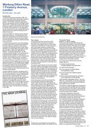
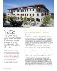
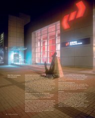
1 top:<br />
Interior of stadium with roof closed.
2.<br />
Bowl framing.<br />
Design principles<br />
Early in the competition, the team decided on a fan-shaped<br />
roof as the best response to the brief. This respected the<br />
natural geometry of a baseball field and offered the best<br />
opportunities for integration with field and bowl. With a span<br />
of around 600ft (183m), the roof dominates the design, and<br />
most of the key principles of moving, stacking, and structural<br />
span were sketched at this early stage. Several meetings<br />
were held with the client team, culminating in a detailed<br />
presentation with drawings, renderings, video, and a<br />
motorised scale model of the roof in operation.<br />
The Bowl<br />
The stadium seating bowl has about 11 000 tons of<br />
exposed steel framing, with concrete slab on metal deck<br />
floors and precast seating above. There are four levels of<br />
seating and concourses, the highest some 110 ft (33.5m)<br />
above the field, forming a splayed U-shape around the field<br />
along first base, home plate, and third base. The plan recalls<br />
traditional American ballparks in its irregular field geometry<br />
(each ballpark has its own quirks). The seating structure<br />
follows this so that plan geometry and setbacks vary at<br />
each level, necessitating many unique connection and<br />
cantilever steelwork designs. Movement joints divide the<br />
bowl into three segments; the wind loads in each are<br />
resisted by steel cross-bracing around the perimeter and<br />
integrated into the concourses. As in traditional ballparks,<br />
beam / column connections are typically bolted, with large<br />
exposed plates. The massive columns supporting the roof<br />
pivots behind home plate feature built-up box sections with<br />
exposed lattice bracing. To speed erection during the cold<br />
months, field bolting was preferred to welding.<br />
For maximum seats with good sightlines, the depth of the<br />
cantilever seating supports had to be minimised, and so<br />
the design was driven by vibration criteria. The stadium is<br />
intended only for baseball, so data from Canadian codes<br />
and advice from <strong>Arup</strong>’s Advanced Technology Group led to<br />
the design criterion that tip acceleration should not exceed<br />
5%g for the first harmonic mode. A time history analysis<br />
was carried out for the 25ft (7.5m) steel seating cantilevers,<br />
using a 2-D SAP computer model of the entire seating<br />
support structure. Modification to the frame bracing<br />
improved vibration performance.<br />
To function properly and control temperatures and airflow<br />
with the roof closed, the stadium has to be effectively an<br />
enclosed space under some conditions - but also act as an<br />
open stadium when the roof is open. The outer walls around<br />
the bowl have a continuous façade, but the outfield area<br />
below the roof track support beam is enclosed by curved,<br />
lightweight Kalwall panels some 100ft (30m) high. To open<br />
the outfield to the outdoors, these move aside on tracks,<br />
with horizontal trusses tying back to the support towers.<br />
The cantilever tower steelwork for the outfield area had to<br />
be designed for reactions from the roof, the weight of the<br />
track beam, wind on the outfield wall, and the horizontal<br />
trusses that carry all the scoreboards.<br />
The lowest, service, level of the stadium is below grade at<br />
the exterior and open to the field on the interior. Poured-inplace<br />
concrete walls and columns with a concrete pan joist<br />
floor above were used, allowing concreting to start while the<br />
steel was being fabricated.<br />
Foundations<br />
The site has uncontrolled fill, organic silts, and granular soil<br />
overlying bedrock that slopes steeply from depths of about<br />
15ft (4.5m) to 55ft (17m). The compressible nature of the<br />
clays meant that spread footings could not be used except<br />
for the lightest loads, and slabs on grade had to be carefully<br />
detailed to accommodate settlements. Cost evaluation of<br />
several alternatives led to two deep foundation systems<br />
being used for the column and retaining wall loads.<br />
The outfield area has the deepest bedrock, so groups of<br />
16in (0.4m) diameter driven steel Monotube pipe piles were<br />
used. The home plate area has 26in (0.66m) and 42in (1.1m)<br />
diameter drilled piers into the bedrock. Foundation design<br />
for the roof supports was a particular challenge, due to the<br />
large overturning loads on the slender outfield towers and<br />
the major horizontal roof loads on the pivot frame supports.<br />
The solution for the towers was a 7.5ft (2.4m) deep mat<br />
under each, supported by over 100 Monotube piles. In the<br />
event, the original pile capacities were not achieved and<br />
thus were increased in size during construction. In the home<br />
plate area, diagonal tie beams below grade distribute lateral<br />
loads between all the pile caps.<br />
THE ARUP JOURNAL 1/2002 25
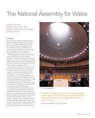
4R<br />
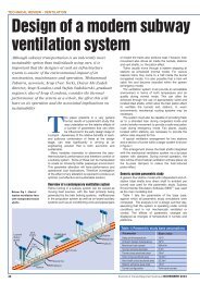
3 below:<br />
Cross-sections of the roof<br />
closed and open.<br />
2R<br />
4R 3R<br />
3R 2R 1<br />
Closed<br />
Open<br />
26 THE ARUP JOURNAL 1/2002<br />
2L 3L 4L<br />
1<br />
2L<br />
3L 4L<br />
The roof<br />
Geometry<br />
At competition stage, the roof design included seven panels<br />
moving on concentric tracks at outfield and behind home<br />
plate, plus two fixed panels. During scheme design the<br />
number of moving segments was reduced and the home<br />
plate track replaced with fixed pivots, so that the final design<br />
has five moving segments and two fixed segments in a fan<br />
shape. Moving panel 1 is the highest, most central, panel<br />
and is aligned with the stadium centreline when the roof is<br />
closed. There are two mirrored versions of each of moving<br />
panel types 2 and 3. The moving panels rotate about pivots<br />
behind home plate, three opening east and two to the west.<br />
When open, the moving panels stack over the fixed ones.<br />
Each moving panel has similar geometry: wedge-shaped<br />
on plan, with the surfaces curved to a maximum 30° slope.<br />
Segments towards the centre of the ballpark are<br />
progressively longer and higher so that they stack above<br />
each other when open, and give maximum clear height at<br />
centre field when closed.<br />
Structural principles<br />
One basic decision was whether to create roof elements<br />
that rely on outward thrust for support, like domes or arches,<br />
or to adopt structures needing only simple support, eg<br />
trusses or tied arches. The team went for the latter - simple<br />
support on the tied arch principle. By avoiding the need for<br />
large outward thrusts, the size of the support structures<br />
around the outfield and home plate could be controlled and<br />
the forces transferring through the mechanism minimised.<br />
Also, each segment was independent, and could thus be<br />
separately designed and constructed.<br />
The main spanning elements needed sufficient overall<br />
structural depth to span across the field and seating, while<br />
also being able to stack neatly one above the other when<br />
open. The inner and outer sides of each panel are, therefore,<br />
different. The long edges of each segment are supported on<br />
arched trusses. On the sides of panels 2, 3, and 4 towards<br />
centre field, these arches are restrained by a tension tie<br />
below, comprising four 4in (100mm) diameter steel cables<br />
suspended from the arch truss. On the outer long side of<br />
panels 2 and 3, and on both sides of panel 1, the edge<br />
trusses are restrained by an upstand compression chord of<br />
60in (1.52m) x 30in (0.76m) fabricated box sections.<br />
Together, the two primary trusses of each panel span about<br />
600ft (183m) across the field and seating. Between the<br />
primary trusses, secondary trusses span to support purlins<br />
and cladding, their upper and lower surfaces cross-braced<br />
to form a stiff ‘torsion box’ to contribute to roof stability.<br />
The upstand / downstand arrangement allows each panel to<br />
maintain truss depth and stack in the open position. Since<br />
much of the total load is the weight of the structure itself<br />
(around 12 000 tons), significant quantities of stronger grade<br />
65 steel were used in addition to grade 50, to reduce the<br />
weight of material to be carried.<br />
Loading<br />
The primary applied loads on the roof are from wind and<br />
snow. Wind analyses by Rowan Williams Davies & Irwin, Inc<br />
(RWDI) at their laboratories in Guelph, Ontario, investigated<br />
the critical directions of flow, to derive maximum design<br />
pressures. They tested rigid and aero-elastic models of<br />
the complete roof, and determined loads derived for<br />
structural analysis, taking into account the dynamic modal<br />
characteristics of each panel.<br />
The basic ground level snow load for Milwaukee is 35lb/ft2 (170kg/m2 ), though distributions determined by RWDI’s<br />
flume testing and computer analysis predicted drifts<br />
up to 200lb/ft2 (1000kg/m2 ) locally at the steps between<br />
roof segments.<br />
Structural analysis<br />
The main elements of the roof were analysed using SAP90 ® ,<br />
together with <strong>Arup</strong>’s GSA software. Stress checks were<br />
made in accordance with the American Institute of Steel<br />
Construction Load resistance factor design code. Analysis<br />
models for each panel included all structural elements<br />
except the purlins. Roughly 100 basic load combinations<br />
were required for each panel, and further analyses also<br />
included frictional effects from the bearings and, notably,<br />
buckling analysis of the upstand chords, which are critical<br />
elements of the roof structure. These upstand chords are<br />
generally in compression, and restrained against buckling by<br />
a combination of their own stiffness and the bending<br />
resistance of the hangers that attach them to the torsionally<br />
stiff roof deck.<br />
A calculation method was needed that could not only<br />
assess the strength of the compression chords themselves,<br />
taking into account the flexibility of the deck and the hangers,<br />
but also determine the restraint forces induced in the hangers<br />
and the deck. Also, a comprehensive assessment of buckling<br />
effects had to be combined with the results of all the primary<br />
loadcases to check the combined stress ratios in the<br />
individual members.<br />
The analysis of the upstand elements was not adequately<br />
addressed in any structural design code, since it required<br />
overall consideration of the buckling behaviour of an entire<br />
roof panel structure. The team had to take into account the<br />
range of potential initial imperfections caused by tolerances<br />
and residual stresses that might affect performance. To build<br />
up understanding and confidence in the design, various<br />
analysis methods were applied, from simple assumptions for<br />
preliminary sizing to sophisticated methods for final analysis.<br />
The latter involved consideration of potential imperfections<br />
based on buckling mode shapes, applied in combination<br />
with normal loads, using a P-delta analysis. The basis of<br />
the method was demonstrated to be equivalent to code<br />
assumptions, and allowed <strong>Arup</strong> to extend the underlying<br />
principles to a far more complex case. This analysis gave<br />
great insight into the structural actions involved and<br />
reinforced confidence in the roof design.<br />
Mechanical systems<br />
The mechanism was designed and constructed by MHI.<br />
The pivots include spherical bearing elements, to receive<br />
both vertical and horizontal loads, while releasing rotations<br />
around all axes. The outfield mechanisms include an<br />
electrically powered bogie under each corner of each moving<br />
panel. A roller bearing was included to allow longitudinal<br />
expansions and contractions up to ±20in (500mm) for each<br />
panel. Each panel runs on its own load-bearing circular<br />
track. The tracks, however, are not concentric, since the<br />
pivots are offset from each other on plan. The mechanical<br />
system includes side-stabilising rails, end buffers, locking<br />
devices for the open and closed positions, and holding<br />
down restraints.<br />
Roof support structures<br />
At the pivot end, the panels are all supported on the<br />
steel pivot frame, spanning between two major columns.<br />
This frame is propped to resist wind loads from the roof,<br />
delivering forces to the bowl structure behind home plate.<br />
At the outfield end the roof panels are supported on curved<br />
rails at high level on a concrete track beam 16ft (4.8m)<br />
deep, spanning some 150ft (45m) between steel-framed<br />
towers. Concrete was chosen due to the curved geometry,<br />
and to provide continuity across spans. Each rail has<br />
its own beam with the four beams tied together, with cross<br />
members, to work as one unit. The resulting open grillage<br />
structure minimises snow build-up around the rails<br />
and mechanisms.<br />
Roof details<br />
As the steel sections were being shipped from Asia,<br />
a bolted structure was required. Most of the connections<br />
use slip critical friction bolts, with cover plates to webs and<br />
flanges. Generic designs were developed, plus many special<br />
conditions to deal with the complex geometry.<br />
The roof cladding includes a perforated acoustic deck, with<br />
insulation and waterproofing membrane on a board substrate.<br />
Above the deck surface, a series of upstand steel guards<br />
stops snowslides, whilst the roof drainage flows to gutters<br />
occupying the full depth of the deck structure at the pivot<br />
and outfield ends of each roof panel. The gutters cascade<br />
from upper to lower panels, discharging into 20in (500mm)<br />
diameter down-pipes.<br />
The roof panels have gaps for structural deflections and to<br />
allow for relative movements between them during opening<br />
and closing, caused by the offsets between pivots. These<br />
gaps are sealed by flexible overlapping flaps.
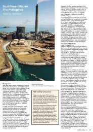
a)<br />
<strong>Arup</strong> was also<br />
consulting<br />
engineer for the<br />
Los Angeles<br />
Dodger Stadium<br />
and the<br />
Paul Brown<br />
Stadium for the<br />
Cincinnati<br />
Bengals.<br />
4 a) to e) below:<br />
Opening the roof.<br />
Los Angeles Dodger Stadium<br />
Jonathan Phillips<br />
In early 1999 <strong>Arup</strong> was approached to provide building<br />
services (mechanical, electrical and plumbing engineering)<br />
for refurbishing the historic Dodger Stadium, built during the<br />
early ‘60s and a major landmark within both Los Angeles<br />
and American baseball. The project was very ambitious and<br />
involved:<br />
• demolition of the club level and<br />
building new executive suites<br />
• refurbishment of the stadium club<br />
• breaking open the field line slab behind home<br />
plate, excavating and creating a new high end<br />
dug out club below grade<br />
• extending the field line seating nearer to home<br />
plate and providing new line expansion seating<br />
• a seismic upgrade to the home plate section<br />
of the stadium.<br />
The project had to be carried out, start to finish, between<br />
the last game of the 1999 season and opening day of the<br />
2000 season.<br />
This provided some six months to do the work, with<br />
expenditure in the order of US$50M of construction cost.<br />
The suites were to be something different and to move<br />
forward the standards of high end corporate entertainment.<br />
The dug out club had similar aspirations - but also the<br />
constraints of head room clearance beneath sloped<br />
precast seating above. NBBJ Sports and Entertainment<br />
provided their usual imaginative concepts to the project for<br />
both architecture and the interior design and produced a<br />
unique experience and level of quality.<br />
Substantial survey work and a flexibility to adapt design<br />
concepts hand-in-hand with the contractors on site as real<br />
conditions became clear were an integral part of both the<br />
project and its success.<br />
d) e)<br />
b)<br />
6.<br />
Home plate at the Dodgers.<br />
5.<br />
One of<br />
the new<br />
executive<br />
suites.<br />
The project pace was punishing and almost every aspect<br />
was on the critical path. Huge credit goes to the project<br />
managers, the contractors, the client team and the <strong>Arup</strong><br />
staff involved for staying the pace and seeing the job<br />
through to the end. Feedback on the finished stadium has<br />
been tremendous and <strong>Arup</strong>’s involvement with the club<br />
and stadium continues to bring project work.<br />
c)<br />
THE ARUP JOURNAL 1/2002<br />
27
28 THE ARUP JOURNAL 1/2002<br />
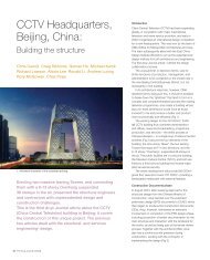
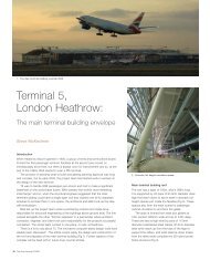
7<br />
<strong>Miller</strong> <strong>Park</strong> stadium: a game in
progress, with the roof open.<br />
THE ARUP JOURNAL 1/2002 29
Crescent walls<br />
On either side of the stadium, glazed crescent walls close<br />
the gap between the seating bowl beneath and the arching<br />
truss of panel 4 above. However, at 580ft (180m) long and<br />
up to 130ft (40m) high, these walls have to do more than<br />
just to support cladding.<br />
The edge of panel 4 facing the field spans the full length of<br />
the stadium, but to reduce steel weight the other edge is<br />
propped by the vertical members of the crescent wall.<br />
Whilst carrying these vertical loads and the cladding’s wind<br />
forces, the wall must also accommodate the geometrical<br />
shift from the regular radial setting out of the roof to the<br />
more irregular bowl columns beneath. Finally, it must allow<br />
panel 4 to move freely longitudinally by ±12in (300mm) as<br />
loading changes, ensuring that damaging movements are<br />
not transmitted to the wall’s cladding. Everything had to be<br />
accomplished with an attractive structure fully visible from<br />
both inside and outside the stadium.<br />
The crescent wall’s truss columns, spaced at between<br />
20 and 40 ft, are supported by the bowl’s columns from<br />
beneath, and horizontally propped at their head by panel 4.<br />
Pairs of truss columns are cross-braced together to form<br />
stable towers, and all are linked horizontally by trusses that<br />
support the cladding. Towers can move independently in<br />
plane, so some cladding trusses have movement joints at<br />
their ends that are mirrored in the cladding.<br />
Key members in the wall are the pairs of ‘swingers’, each<br />
up to 29.5ft (9m) long. Pinned at both ends, these carry<br />
vertical loads from the panel above to a bracket part way<br />
up the truss columns. The swingers can rock to and fro<br />
to accommodate the longitudinal expansion of the panel,<br />
isolating the truss columns and cladding from distortion.<br />
Construction<br />
Groundworks and bowl construction<br />
The site was previously a landfill and so, once the piles were<br />
in place and before concreting, a barrier was installed over<br />
the subsoil to prevent methane escaping. The steel in the<br />
bowl structure was fabricated and supplied by Havens Steel<br />
of Kansas City, and is remarkable in that it not only supports<br />
the stadium itself but also the roof above it, which is of<br />
almost equal weight. Columns, some over 300lbs/ft<br />
(450kgs/m) in weight, were erected first with floor beams<br />
bolted in place temporarily, aiding stability until the structure<br />
could be plumbed. Trusses for the club level cantilevers then<br />
arrived in segments and were welded complete in the field<br />
using a purpose-built jig. Cranes erected the finished trusses<br />
into place on the columns whereupon the floor decking was<br />
laid out ready for the slab pours. Mechanical services and<br />
architectural finishes promptly followed.<br />
Roof steel supply and fabrication<br />
MHI was subcontractor for the roof steelwork - which was<br />
much travelled. The high strength Grade 65 and 50 material<br />
was forged at Trade Arbed Inc in Luxembourg, and then<br />
shipped to MHI’s fabrication yards in Japan and China. Now<br />
with shop welds and bolt holes for field assembly, the steel<br />
then took another sea voyage to Los Angeles, from whence<br />
it finally came by lorry to Milwaukee. Offsite at local yards,<br />
the separate elements were assembled like a vast jigsaw<br />
puzzle into recognisable truss sections, and then trucked to<br />
the field for cranes to slot them together. These partial<br />
sections of roof, called blocks, weighed around 300 tons<br />
(275 tonnes) and measured about 150ft (45m) across.<br />
Roof construction<br />
Once assembled, the blocks were craned up to sit on<br />
the columns of the crescent wall and shoring towers. Then,<br />
with bolted splices between them and tie cables erected<br />
and tightened, one side of a panel could be free-spanned<br />
the full 600ft (180m). This done, the other side of the panel,<br />
containing the upstand, could be jacked up to fan out the<br />
hangers so as to fit in the overlong box chord.<br />
30 THE ARUP JOURNAL 1/2002<br />
Pivot<br />
Compression chord:<br />
60 in x 30 in (1.52m x 760mm)<br />
Tie: four 4in (100mm) cables<br />
This over-length favourably redistributed forces within the<br />
truss. In the construction sequence developed by the<br />
contractor, the panel above used both the free-spanning<br />
panel below and the shoring tower and crescent wall<br />
structures for temporary support of its separate blocks until it<br />
too could be made to free-span. This complex load-sharing<br />
arrangement, or ‘stacking’, involved using large jacks on<br />
roller bearings smooth enough to be pushed with a<br />
finger, to accommodate the multi-directional differences<br />
in movement between the segments.<br />
Crane collapse<br />
On 14 July 1999, Lampson’s ‘Big Blue’, the large crawler<br />
crane that was erecting the roof panels, collapsed in high<br />
winds while carry a large section of panel 4R. Three workers<br />
were killed, the building suffered $100M of damage and a<br />
year’s delay, and the lives of all those involved with <strong>Miller</strong><br />
<strong>Park</strong> and the community of Milwaukee were forever affected.<br />
In the months following, all parties worked together to<br />
fulfil the wishes of that community and rebuild the stadium.<br />
A Demag crane replaced the destroyed Lampson and<br />
completed the project without incident; when raised it was<br />
one of the tallest structures in Milwaukee - and it could<br />
move as well.<br />
9.<br />
Block assembly.<br />
10.<br />
Block erection.<br />
8.<br />
Typical truss.<br />
11 above:<br />
Crescent wall.
13.<br />
First<br />
movement<br />
of panel 1.<br />
Paul Brown Stadium<br />
Bruce Gibbons<br />
The existing Cincinnati Riverfront stadium, built in the<br />
1960s, was typical of its genre, being configured for both<br />
football and baseball. Nowadays demands for improved<br />
sightlines, and added revenue-generating streams for the<br />
teams such as luxury suites and club-seating, have led to<br />
their replacement with dedicated facilities to specific sports.<br />
The new Paul Brown Stadium for the Cincinnati Bengals<br />
opened in August 2000 to wide critical acclaim.<br />
The contemporary design of this National Football<br />
League stadium breaks the mould of traditional designs<br />
by opening the seating bowl at the end-zones, a strategy<br />
which eliminates the undesirable corner seats and allows<br />
the city to interact with the action inside. The facility<br />
comprises luxury suites, club areas, concessions, team<br />
offices, and training facilities on eight levels.<br />
The elegant swooping signature roof is a key feature of<br />
the building’s design, providing intimacy within the bowl<br />
and focusing attention towards the field.<br />
<strong>Arup</strong> was structural engineer for the project, which was<br />
built on a fast-track schedule requiring a close working<br />
relationship with the construction manager.<br />
Awards<br />
• Chicago Atheneum American Architecture Award 1999<br />
• American Institute of Steel Construction, IDEAS,<br />
Innovative Design and Excellence in Architecture<br />
Using Structural Steel, Award 2000<br />
12.<br />
Pivot frame.<br />
15. Main entrance.<br />
Stadium facts & figures*<br />
• home of the Cincinnati Bengals<br />
National Football League team<br />
• 65 535 seats on three levels,<br />
including 7600 club seats and 114 private suites<br />
• total enclosed area: 1 850 000ft 2 (172 000m 2 )<br />
• over 11 000 tons of steel reinforcing bars<br />
• approximately 95 000yds 3 (72 500m 3 ) of concrete<br />
• over 9100 tons of structural steel<br />
www.bengals.com* (Official web site of the Cincinnati Bengals)<br />
Electrical design<br />
Power distribution<br />
Power supplies have to be maintained with minimum<br />
disruption during games. After careful evaluation, cost benefit<br />
analysis, and co-ordination with the local power company,<br />
a dual-feed 26.4kV primary service from Wisconsin Electrical<br />
Power Company (WEP CO) was specified. This was based<br />
around an automatic change-over design to allow WEP CO<br />
to switch from one circuit to another in the event of failure.<br />
Two separate circuits were brought to the stadium and<br />
terminated in 35kV rated switchgear, including a tie switch<br />
for switching over to either of the two circuits. Two WEP CO<br />
utility meters were housed in the switchgear, in a single-storey<br />
high voltage switch room near the central plant.<br />
From this switchgear, two sets of high voltage cables in<br />
overhead conduit were installed in the service level through<br />
the utility corridors.<br />
14.<br />
Track beam.<br />
THE ARUP JOURNAL 1/2002 31
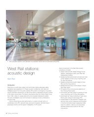
16 above:<br />
The roof and outfield wall<br />
in open position.<br />
17 right:<br />
The roof and outfield wall<br />
in closed position.<br />
Early on it was realised that soil conditions were unsuitable<br />
for any major conduits to be directly buried; also any conduit<br />
penetrations of the soil protective membrane had to be<br />
avoided. The architects helped co-ordinate a route for the<br />
conduits with other services, at high level within a dedicated<br />
zone to one side of the service corridor. Other services<br />
running here include the mechanical ductwork, fire sprinkler<br />
lines, plumbing pipes, beer supply pipes and cable trays for<br />
the various communication cables, sound and broadcasting<br />
cables. Vehicle clearance was also necessary here, and<br />
all the services required maintenance access as well as<br />
physical separation.<br />
Predicted load requirements and the need for optimum<br />
voltage drop distribution required five electrical equipment<br />
rooms along the service level. For the all-important<br />
maintenance of power during games, a double-ended<br />
substation installation was selected. Each unit substation<br />
comprises a high voltage switch and fuse, a cast coil<br />
transformer, and low voltage circuit-breakers. A cross-tie<br />
circuit breaker is provided between substations, allowing<br />
load sharing should a transformer fail, and additional<br />
redundancy. The transformers have aluminum windings.<br />
From the substation, power is distributed at 480V/277V,<br />
three-phase, four-wire. Vertical electrical aluminum busway<br />
risers at strategic locations supply upper electrical rooms,<br />
each housing electrical panel boards, distribution boards,<br />
and dry type transformers for 280Y/120V, three-phase,<br />
four-wire systems. To avoid problems from generated<br />
harmonics, K-13 rated transformers were used to service<br />
sensitive electronics equipment for the sound and<br />
broadcasting systems, press room, and office computers.<br />
Motor control centres - circuit breakers and starters -<br />
at the mechanical rooms serve the HVAC equipment.<br />
For variable frequency drives, drive isolation transformers<br />
reduce harmonic distortion to the electrical system.<br />
32 THE ARUP JOURNAL 1/2002<br />
‘The client’s wish<br />
for a modern<br />
baseball park<br />
combining a<br />
state-of-the-art<br />
roof with a<br />
traditional<br />
architectural feel<br />
was successfully<br />
achieved.’<br />
Emergency power<br />
The multiple substations reduce the risk of complete power<br />
failure to a minimum. The general lighting and sports lighting<br />
is served from multiple sources to reduce the risk of complete<br />
darkness, but emergency power was required for fire pumps,<br />
emergency egress lighting, all essential broadcasting systems,<br />
smoke evacuation system, and elevators.<br />
Two outdoor emergency generators serve the two halves of<br />
the stadium, operating at 480V/277V, three-phase, four-wire,<br />
with their own under-frame fuel tanks. Auto transfer switches<br />
and emergency switch boards are located in the electrical<br />
room. Emergency power is distributed via power distribution<br />
boards for critical equipment and lighting, with dry type<br />
transformers for the 208Y/120V system.<br />
Each major broadcasting area has dedicated K-rated<br />
transformers and panel boards. Separate neutral wires for<br />
each branch circuit minimise overload on the neutral wires<br />
from harmonic effects. Touring company switches are<br />
provided for visiting TV companies as well as performers.<br />
Special raceway and designated routing was developed to<br />
avoid electrical noise interference to the broadcast and<br />
sound equipment from other electrical sources.<br />
Lighting<br />
Both the major lighting systems use metal halide lamps.<br />
The general stadium lighting is from overhead pendant<br />
fixtures, whilst the field sports lighting, illuminating the<br />
playing area, is mounted on the edge of an access and<br />
maintenance catwalk, together with dedicated lighting<br />
control panels. All the fixtures operate at 277V, one-phase,<br />
except those on the emergency circuits, which are 480V.<br />
A DOS-based central processing unit, video monitor,<br />
and keyboard control the lighting, with communication for<br />
integration with the lighting controllers for the field and<br />
architectural lighting as well as the perimeter lighting.<br />
Emergency, security, and some non-public spaces are<br />
separate from the lighting control system. Local manual<br />
control overrides were also provided at each lighting panel<br />
in case of lighting control system failure.
Lightning protection<br />
Single masts mounted at roof level form the lightning<br />
prevention system. Down conductors connect the masts<br />
to ground rods around the building perimeter.<br />
Fire alarm system<br />
This is an addressable system with microprocessor-based<br />
control panels. The main control panel, with a graphic<br />
display of the stadium, is in the fire control room, linked with<br />
remote transponder units strategically located throughout<br />
the stadium. Pull stations are at the emergency exits.<br />
Smoke detector coverage is to code requirements, including<br />
the atrium, smoke-free corridors, elevator lobbies, elevator<br />
shafts, mechanical and electrical rooms, and signal<br />
equipment rooms. There are detectors in the mechanical<br />
ductwork for smoke control and HVAC equipment shutdown.<br />
The fire alarm system has a fireman’s microphone interlinked<br />
with the stadium public address system, which in the event<br />
of emergency is automatically overridden by fire alarm<br />
announcements and the fireman’s microphone.<br />
Mechanical / HVAC<br />
Originally the seating bowl was to be air-conditioned and<br />
heated whenever the roof is closed. Due to the use of natural<br />
turf the roof is mostly open, and only closed at game time<br />
during inclement weather - originally defined as rain, snow<br />
(which can occur through May in Milwaukee), and excessive<br />
heat and humidity. This was reduced to rain and snow due<br />
to the cost of cooling plant necessary for the bowl (about<br />
6500 tons / 6000 tonnes). Although space was left in the<br />
building and bowl systems for cooling to be added in future,<br />
heating was the dominant condition for sizing the air systems.<br />
A wind study analysed the summer airflow through the bowl<br />
with the roof closed for shade during play, and showed that<br />
the primary wind condition was towards the outfield wall.<br />
This was therefore made operable to allow this wind to<br />
penetrate the bowl.<br />
Additionally, operable louvers above the terrace seating relieve<br />
the hot air rising from the occupants and seating deck. Air is<br />
thus induced across the fans giving good air movement,<br />
which can be supplemented by the heating system. Due to<br />
the roof stacking, most of the seating bowl is in shade and<br />
thus the concrete does not receive direct solar radiation -<br />
a significant advantage for not providing cooling.<br />
The focus of the design was thus to heat the bowl and<br />
concourses by 30°F (17°C) above ambient. The strategy<br />
adopted was to introduce air via jet nozzles above each<br />
seating level to create an envelope of warm air, supplemented<br />
by jets at the highest level introducing more warm air into<br />
the downdraught from the roof, creating the dominant air<br />
movement in the space. The two airstreams mixing is<br />
enough to temper this cold air stream but not prevent its<br />
downward momentum. The airflow then rises due to the<br />
gains above the seating deck. Air is returned through the<br />
concourse and vomitories to the air handling units (AHUs).<br />
Displacement ventilation was considered, but abandoned<br />
early due to the primary function being heating - plus<br />
hygiene considerations (Coke, beer and peanuts is a<br />
potent mixture). The team spent much time with the<br />
client discussing operation of the roof and heating system.<br />
The original requirement was to close the roof and start the<br />
system assuming an instantaneous comfort condition.<br />
This had to be discussed, and an early closing implemented<br />
to allow time to overcome the cold built-up within the seating<br />
deck. This required a change in operation strategy so that<br />
the roof would be closed.<br />
Five AHUs serve the lower field bowl (90 000ft3 (2550m3 )/min<br />
total), four serve the club level bowl (20 000ft3 (570m3 )/min<br />
each), and two the terrace level bowl (94 000ft3 (2660m3 )/min<br />
each). Each unit contains indirect gas-fired heaters to give<br />
70 000Mbh heating capacity for the bowl and concourses,<br />
as well as smoke control capability.<br />
These systems utilise a minimum outside air quantity of 5ft3 (0.14m3 )/min per person. The quantity of air equivalent to<br />
the ventilation requirements for the bowl is exhausted by the<br />
concession hoods or dissipated through the façades.<br />
This system was checked and optimised by a computational<br />
fluid dynamics (CFD) study, allowing the final permeability of<br />
the exterior skin to be determined as well as verifying the<br />
total capacity of the systems. By offsetting permeability of<br />
18.<br />
Players warming up in the new stadium.<br />
the fabric (final 5% open) against system size it was possible<br />
to work with the architect and contractor to significantly<br />
reduce the size of the mechanical system and save costs.<br />
The primary move was to detail a flap that closed the gap<br />
between each roof panel. The half-bowl CFD model required<br />
420 000 cells. The external skin pressure coefficients were<br />
determined from the wind study. Both winter and summer<br />
conditions were studied, the latter showing enough air<br />
movement in most of the seating area for adequate comfort.<br />
Besides the seating bowl there is an additional 300 000ft2 (27 800m2 ) of enclosed, fully conditioned space including<br />
offices, restaurants, locker rooms, and storage, all served by<br />
conventional air systems with distributed AHUs adjacent.<br />
These have a 1600 ton (1460 tonnes) central cooling plant<br />
and 33 000Mbh hot water heating plant which also gives<br />
frost protection to the turf via buried pipes. This system is<br />
only used before game time so the same boiler plant can be<br />
used without increasing overall capacity. Both systems<br />
contain 30% ethylene glycol to protect against freezing.<br />
The concourse food services have local split system heat<br />
pumps above each unit; a total of some 53 000ft3 (1500m3 )/min of grease exhaust ascends to the roof.<br />
Public reaction<br />
The public has been overwhelmingly enthusiastic about the<br />
new stadium. At topping-out, they covered the final upstand<br />
segment with thousands of signatures, and months later<br />
hundreds of thousands of people turned up for open houses<br />
before the start of the season, jamming the freeways.<br />
The pre-season games and the 6 April opener itself were<br />
spectacular events featuring tributes to everyone involved<br />
and the community itself, which hopes to finally shake its<br />
association with dated TV shows and the like. Indeed, the<br />
fact that the stadium has been built there at all is a testament<br />
to its spirit - apparent during the early games when<br />
thousands of seats stood empty as people wandered<br />
around the building in awe, jaws dropping at the first sight of<br />
the roof high above their heads like a man-made sky soaring<br />
into the distance. Most of them also waited after the end of<br />
the game to watch the roof move in a silent, smooth,<br />
10-minute motion to the sounds of the opening of<br />
Strauss’s Also Sprach Zarathustra from 2001: A Space<br />
Odyssey, cheering as it did so. And, in a month when it<br />
has been known to snow, for once people complained of<br />
the stadium actually being too warm!<br />
Conclusion<br />
Dirt from the batter’s mound in the original park was<br />
ceremonially placed in the new field, and the traditional<br />
tower where the mascot ‘Bernie Brewer’ slides down into a<br />
replica of home plate when a home run is scored has also<br />
moved into its new residence. At the opening game the first<br />
pitch was thrown by President George W Bush.<br />
The Brewers certainly have a unique, state-of-the-art park -<br />
and an indication of its wider impact came in October 2001<br />
when the magazine Popular Science gave the roof one of<br />
its 2001 ‘Best of What’s New’ awards in the ‘General<br />
Technology’ category.<br />
Credits<br />
Owner:<br />
Southeast Wisconsin<br />
Professional Baseball <strong>Park</strong><br />
District<br />
Architects:<br />
HKS Inc<br />
NBBJ Sports and<br />
Entertainment<br />
Epstein Uhen Architects<br />
Construction manager:<br />
HCH joint venture<br />
Consulting engineer:<br />
<strong>Arup</strong> Arif Bekiroglu, Jon Bell,<br />
Luis Bernal, Jacob Chan,<br />
John Chan, King-Le Chang,<br />
Chung-Chi Chu, Keith Chung,<br />
Tony Cocea, Chuan Do,<br />
John Gautrey, John Hewitt,<br />
Richard Hough,<br />
Swaminathan Krishnan,<br />
Samir Kulenovic, Morgan Lam,<br />
Gary Lau, Alan Locke,<br />
Surinder Mann, Hideki<br />
Nishizawa, Barry Ralphs,<br />
John T Roberts, Bruno Sum,<br />
Dan Ursea, Catherine Wells<br />
Subconsultants:<br />
FLAD Structural Engineers<br />
(structural)<br />
PSJ Engineering, Inc<br />
(mechanical/plumbing/<br />
fire protection)<br />
Powertek Engineering, Inc.<br />
(electrical)<br />
Roof steelwork and<br />
mechanism:<br />
Mitsubishi Heavy Industries<br />
America<br />
Bowl steelwork:<br />
Havens Steel<br />
HVAC<br />
Advance Mechanical<br />
Electrical:<br />
Pieper<br />
Illustrations:<br />
1, 2, 4, 7, 15-18: Tim Griffith<br />
3: Daniel Blackhall<br />
5, 6: ©Milroy & McAleer<br />
8: Sean McDermott<br />
9-14: Surinder Mann<br />
THE ARUP JOURNAL 1/2002 33