PDS_VERSION_ID= PDS3 - PDS Small Bodies Node
PDS_VERSION_ID= PDS3 - PDS Small Bodies Node
PDS_VERSION_ID= PDS3 - PDS Small Bodies Node

Create successful ePaper yourself
Turn your PDF publications into a flip-book with our unique Google optimized e-Paper software.
DESCRIPTION = "FITS format defined in NASA/Science Office Standards<br />
Technology 100-1.0 "<br />
END_OBJECT = HEADER<br />
OBJECT = IMAGE<br />
LINE_SAMPLES = 241<br />
LINES = 241<br />
SAMPLE_BITS = 32<br />
SAMPLE_TYPE = “IEEE_REAL”<br />
AXIS_ORDER_TYPE = “FIRST_INDEX_FASTEST”<br />
UNIT = " W.cm**-2.sr**-1"<br />
SAMPLING_PARAMETER_NAME = ("RA---CAR","DEC--CAR")<br />
SAMPLING_PARAMETER_INTERVAL = (-0.004166666884, 0.004166666884)<br />
SAMPLING_PARAMETER_UNIT = ("DEGREE/PIXEL","DEGREE/PIXEL")<br />
SAMPLE_DISPLAY_DIRECTION = "RIGHT"<br />
LINE_DISPLAY_DIRECTION = "UP"<br />
MAXIMUM = 2.1979793E-14<br />
MINIMUM = 1.6942433E-15<br />
END_OBJECT = IMAGE<br />
NOTE ="<br />
1) IPAC HIRES iteration number = 1.<br />
2) EXPOSURE_DURATION is the actual time spent observing the target.<br />
The total duration of the observation is 764 seconds. It includes<br />
time used to make attitude updates at the beginning and end of the<br />
observation and is the difference in START_TIME and STOP_TIME.<br />
3) B1950_RIGHT_ASCENSION and B1950_DECLINATION<br />
refer to the right ascension and declination<br />
assigned to the pixel at the center of the image.<br />
4) North is up and East is to the left, based on SAMPLE_DISPLAY_DIRECTION<br />
and SAMPLE_LINE_DIRECTION.5) ’RA---CAR‘ and ’DEC--CAR‘ values for<br />
SAMPLING_PARAMETER_NAME indicate<br />
a Plate Carree projection for right ascension and declination.<br />
For more information see CALABRETTA&GREISEN02 and GREISEN&CALABRETTA02<br />
6) NOT_APPLICABLE_CONSTANT of -9999.00 identifies an array element outside<br />
the scan area<br />
7) The effective beam sizes, provided by HIRES processing are<br />
included below to illustrate how the effective spatial resolution<br />
varies over the map by providing the dimensions of a rectangular<br />
Gaussian profile of a resolution element at different locations<br />
in the image.<br />
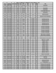
Effective Beam Sizes in the Beam Sample Image (Band 4,<br />
20 Iterations)<br />
(I,J) = IRAF pixel coordinates; Maj & Min = FWHM axes of Gaussian fit;<br />
PosAng = position angle, East of North; Spike & Bckgrnd are model inputs;<br />
number of pixels into which spike is smeared is on the order of Spike/Peak<br />
Pixel (I,J) RA Dec Maj Min PosAng RA/DecErr Peak Spike Bckgrnd<br />
‘ ‘ deg ‘ ‘ Jy/pix Jy Jy/pix<br />
121 25 125609.0 -010140 128 82 118 -2 1 0.205 10.00 0.001<br />
169 25 125521.0 -010140 129 84 115 1 3 0.199 10.00 0.002<br />
217 25 125433.0 -010140 162 79 120 4 -3 0.125 10.00 0.000<br />
73 73 125657.0 004940 82 71 11 -13 7 0.022 10.00 0.000<br />
121 73 125609.0 004940 149 97 120 -3 4 0.144 10.00 0.000<br />
169 73 125521.0 004940 130 86 119 -2 1 0.177 10.00 0.001<br />
73 121 125657.0 003740 162 81 118 -3 0 0.115 10.00 0.000<br />
121 121 125609.0 003740 132 86 118 0 -1 0.167 10.00 0.000<br />
169 121 125521.0 003740 168 87 118 -4 2 0.116 10.00 0.000<br />
73 169 125657.0 002540 129 86 119 2 0 0.177 10.00 0.002<br />
121 169 125609.0 002540 133 86 119 -4 2 0.196 10.00 0.000<br />
169 169 125521.0 002540 89 71 167 -7 10 0.051 10.00 0.000<br />
25 217 125745.0 001340 158 82 118 15 -10 0.119 10.00 0.000<br />
73 217 125657.0 001340 153 86 124 -17 6 0.153 10.00 0.001