built; by ACCURPRESS - Sterling Machinery
built; by ACCURPRESS - Sterling Machinery
built; by ACCURPRESS - Sterling Machinery

Create successful ePaper yourself
Turn your PDF publications into a flip-book with our unique Google optimized e-Paper software.
s<br />
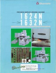
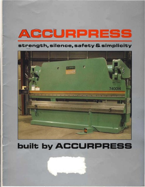
st;rengt;h. silence. safet;y & slmplicit:y<br />
n......<br />
<strong>built</strong>; <strong>by</strong> <strong>ACCURPRESS</strong>
A<br />
E<br />
Accurpress with plants located in Richmond,<br />
British Columbia and Willmar, Minnesota, has fast<br />
become one of North America's most progressive<br />
press brake and shear manufacturers.<br />
To meet the demands of a rapidly changing world,<br />
Accurpress has spent hours of careful study and<br />
engineering to perfect the press brake as it is<br />
today.<br />
Features that distinguish the unique Accurpress<br />
brake among others are Ultimate durability,<br />
Rigidity, Simplicity, and Affordability.<br />
High accuracies are maintained <strong>by</strong> the most up<br />
to date hydraulic. electrical and bearing systems.<br />
Accurpress manufactures a range of press brakes<br />
from 50 to 3000 tons and all units are covered <strong>by</strong><br />
an excellent parts and labour warranty, to be free<br />
of defects in material and workmanship, under<br />
correct use and normal operating conditions.<br />
T
EBB<br />
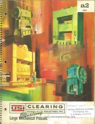
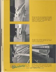
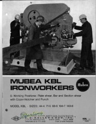
Pictured below is a typical<br />
example of a heavy duty giant<br />
size precision press brake. This<br />
press contains no bronze<br />
bushings. All bearings are<br />
space age zero maintenance<br />
type running on heat treated<br />
hard chrome shafts.<br />
The advanced design of this<br />
press, and rigid metallurgical<br />
control together with careful<br />
construction, guarantee<br />
lifetime durability and precision<br />
accuracy.<br />
1250 TON 25'
FRAME<br />
The Accurpress brake is known for its heavy duty frame<br />
construction. The entire machine is welded from A36<br />
Structural Steel Plate to give ultimate rigidity and<br />
durability.<br />
BED DESIGN<br />
The Accurpress features an I-beam bed design. This<br />
design offers two attractive features - the least bed<br />
deflection possible without going below floor level and a<br />
wide working area for supporting punching dies and<br />
special tooling.<br />
For our larger press brakes. under-the-floor beds are<br />
bolted to the brake at floor level. still enabling the main<br />
frame to be fUlly welded.<br />
RAM LEVEL<br />
The parallel accuracy of the ram is guaranteed <strong>by</strong> the use<br />
of the large torque tube welded at each end to the double<br />
rocker arms. thus synchronizing the hydraulic cylinders.<br />
Ram parallelism is easily adjusted <strong>by</strong> rotating an eccentric<br />
shaft on the left end of the machine via a wrench or on the<br />
larger press brakes <strong>by</strong> an electric motor. Ram parallel<br />
adjustment is necessary for trimming the ram to various<br />
die characteristics and for fade out work.<br />
FOOT SWITCH WITH PEDESTAL<br />
This feature is standard ONLY on models of 250 tons<br />
capacity or larger. Easily moved from place to place. and<br />
wired with an on-off jog switch. it saves set-up time as the<br />
operator can control all ram movement from where he<br />
stands.
ELECTRICS<br />
All highest quality electrical components are used<br />
and mounted within an all steel hinged door<br />
enclosure c/w a disconnect for operator safety.<br />
This switch shuts off power before the door can<br />
be opened. All controls are at 115 volts and not at<br />
line voltage, via a transformer within the cabinet<br />
together with motor starter.<br />
Three micro switches function to control ram<br />
position and speeds. Two are mounted on the<br />
cabinet providing the up stop and speed change<br />
over. The third micro switch is remotely mounted<br />
for ultimate accuracy and provides the depth bend<br />
point. Typical repeat accuracy of the ram is t..OO1".<br />
CONTROL SYSTEM<br />
Accurpress originated the safety sequence<br />
footswitch system as follows: A 3 position<br />
Linemaster safety footswitch controls ram<br />
movement. This enables the operator to stop ram<br />
travel at any time up or down. and have full<br />
control of ram action. The release of the foot<br />
pedal automatically returns the ram to the up<br />
position. The depth of the bend angle is adjusted<br />
via the engraved Dial-a-bend control above the<br />
electrical cabinet. This incremented dial equals<br />
.010" per increment and its repeat accuracy<br />
enables the logging of information for repeat<br />
bends at a later date. This in conjunction with a<br />
micrometer barrel enables .001" adjustments. Also<br />
standard on every Accurpress is a manual 4<br />
position turrel depth gauge. allowing 4 various<br />
pre-set bend angles. A red light on the cabinet<br />
indicates when the micro switch has been<br />
activated for the ease of setting bend angles. The<br />
ram can be cycled from full length strokes down<br />
to 1/8" strokes anywhere within the stroke range.<br />
Both stroke length and speeds are quickly<br />
adjusted via aluminium sliding cams.<br />
AUTOMATIC SIX POSITION DEPTH STOP<br />
(OPTIONAL)<br />
This is an advanced Mitsubishi control unit to give<br />
an operator up to six depth positions. Just one<br />
position can be programmed in or up to six<br />
positions depending on the job requirement.<br />
The set up is very simple. The microswitch<br />
selector switches must be in the "off" position<br />
except the position which is being set up. This<br />
particular switch is turned to the "on" position and<br />
the ram is jogged down to the desired bend angle.<br />
The sliding rod is then adjusted down to the limit<br />
switch until the red light appears to indicate the<br />
switch has been activated and the bend angle set.<br />
These same steps are required until all desired<br />
positions have been programmed.<br />
AUTOCYCLING<br />
Extra electrical relays in the control cabinet<br />
provide an autocycling control feature. Rotating<br />
the selector switch over from "manual" to "auto"<br />
causes the ram to cycle up and down between the<br />
adjustable limit positions provided the foot switch<br />
pedal is depressed. On releasing the pedal the ram<br />
will return to the fully up position and stop until<br />
the pedal is depressed again.
BACK GAUGE<br />
The standard back gauge is a heavy duty. rigid design<br />
constructed of precision steel components. The back<br />
gauge is adjusted both vertically and horizontally from<br />
rear of press brake via hand wheels. Horizontal travel Is<br />
0-27 inches. The back gauge also Includes a cross bar<br />
with adjustment fingers.<br />
PAINT AND FINISH<br />
At Accurpress we take extreme care in the finish quality<br />
of all our machines. All welds and plate surfaces are filled.<br />
sanded, and three coats or more of safety green applied.<br />
leaving the press beautifully finished. Before shipment all<br />
machine surfaces are rust proofed insuring top quality<br />
from our plant to your plant.<br />
BEARINGS<br />
All bearings used <strong>by</strong> Accurpress are extremely high<br />
quality. running on heat treated. hardened chrome shafts.<br />
These spherical self-aligning bearings never require<br />
lubrication. They are <strong>built</strong> to last the lifetime of the press<br />
brake with zero clearance.<br />
THE WAYS BOX<br />
The ram is guided <strong>by</strong> pre-loaded low friclion silicone poly.<br />
providing zero maintenance precision ram guidance. This<br />
material is contained in wrap around long length ways<br />
boxes running on large precision ground bars for lifetime<br />
trouble free service.<br />
HYDRAULICS<br />
Both Simplicity and Dependability are the two main<br />
ingredients that compose the hydraulic unit.<br />
All standard North American components are used <strong>by</strong><br />
Accurpress and the circuit is of such a progressive design<br />
that only two valves are used for total control of the<br />
system. One valve for each side of the low noise level<br />
double vane pump provides the two down speeds for ram<br />
and the high return speed.<br />
The unit itself is mounted behind the bed in a safe,<br />
accessible location for noise reduction and safety. The<br />
motor. pump and valves are integral as a unit on the large<br />
tank and the system is protected <strong>by</strong> a safety hydraulic<br />
relief valve which is set at a specific P.S.!. setting to<br />
protect machine. tools and operator.<br />
The hydraulic cylinders are manufactured <strong>by</strong> Accurpress<br />
from seamless tubing. Parker Type B Polypak and<br />
Disogrin Compound 9250 seals assure excellent sealing<br />
while Molygard wear rings and plated cylinder rods<br />
provide lifetime durability.
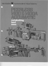
.........cu p E P 10 t DIUI T<br />
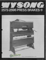
FRONT OPERATED MANUAL BACK GAUGE<br />
This is a heavy duty precision back gauge bolted<br />
to the back of the press brake and operated <strong>by</strong> a<br />
rotary handle from the front. Range of adjustment<br />
is from 0-27". Gauge position indication is<br />
provided <strong>by</strong> a high quality Durant Digital<br />
Mechanical Readout.<br />
POWER OPERATED BACK GAUGES<br />
Electric gear reducer push button operated. All<br />
other features are the same as the manual<br />
operated back gauge.<br />
OIL COOLER<br />
The oil cooler is standard on all press brakes 160<br />
tons and larger. On smaller machines we<br />
recommend a cooler be used if it is going to be<br />
used in continuous production work or if the<br />
machine is located in a place where the air<br />
temperature exceeds 70 degrees F.<br />
SECOND FOOT SWITCH<br />
Some users may want a second foot switch wired<br />
in so that the press will only function when both<br />
foot pedals are depressed. Raising either foot<br />
pedal will cause the ram to raise.<br />
For single operator use a two position selector<br />
switch on the electrical cabinet allows selection of<br />
one or both foot switches.<br />
OSHA CONTROL BAR<br />
To keep the operator's hands away from the press<br />
dies, an electrical control box can be attached to<br />
the ram, containing two palm buttons which must<br />
both be depressed to lower the ram. A selector<br />
switch is provided on the electrical cabinet to<br />
select either this mode of operation or<br />
alternatively, the normal foot switch. The control<br />
box also has an electric motor "stop" button and<br />
motor running indicator light.<br />
SWING STOCK ARMS<br />
To facilitate supporting the plate being formed, 24<br />
inch support arms are available. When not being<br />
used they simply fold backwards against the bed<br />
of the press brake.<br />
ANGLE PLATES<br />
To increase the bed or ram work surface area,<br />
angle plates can be supplied 5lh x 5 1 h x length.<br />
The angles are bolted to the bed and ram and both<br />
front and back.<br />
TONNAGE CONTROL<br />
Tonnage control is available which will limit the<br />
pressing tonnage to a pre-set load.<br />
,he press tonnage is monitored <strong>by</strong> observing the<br />
ydraulic system pressure and tonnage<br />
conversion table. This system permits the operator<br />
to manually adjust the available tonnage and is a<br />
recommended feature when using bottoming dies<br />
;n lieu of air bending.<br />
MACHINE GROOVE IN BED<br />
Standard product press brakes have a flat<br />
machined bed surface. If a 3/4" wide groove is<br />
required in the centre of the bed this must be<br />
specified with the order. A smooth bed surface<br />
allows positioning of the lower die to suit the<br />
upper die and this standard surface satisfies<br />
almost all the braking applications of our press<br />
brakes.<br />
POWER ECCENTRIC<br />
On 320 ton press brakes and larger, a power<br />
operated eccentric is standard. This is optional on<br />
smaller presses.<br />
The power eccentric is controlled <strong>by</strong> two push<br />
buttons on press bed.<br />
PRESS BRAKE CYCLE TIME<br />
A modified hydraulic system is available to<br />
increase press cycle time.<br />
HARD RAM INSERTS<br />
Hard ram inserts are to protect the ram under high<br />
tonnages where there is a possibility of the upper<br />
male die being pushed up into the ram. This option<br />
IS recommended on large tonnage machines<br />
where short dies are going to be used.
AC<br />
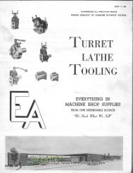
P ES 1IC ....In..E PECIFI TI NS<br />
7606 60 6 1I 10 ge 6 52 34 4 78 40 70 8 14 6 8 135 28 275 10 6,000<br />
7608 60 7 X 11 ge 8 76 34 4 102 40 70 8 14 6 8 135 28 275 10 7,300<br />
76010 60 8 X 1298 10 100 34 4 126 40 70 8 14 6 8 135 28 275 10 8,600<br />
71008 100 8 X 3/16 8 76 34 6 102 42 86 8 14 6 8 97 28 190 20 9,500<br />
710010 100 8 x 3/16 10 98 34 6 126 42 86 8 14 6 8 97 28 190 20 12.000<br />
710012 100 8 x 3/16 12 122 34 6 150 42 86 8 14 6 8 97 28 190 20 13.000<br />
713010 130 7 x 1/4 10 98 34 5 126 48 84 8 14 6 10 76 28 160 20 13,000<br />
713012 130 7 x 1/4 12 122 34 5 150 48 90 8 14 6 10 76 28 160 20 15,000<br />
713014 130 10 x 3/16 14 148 34 5 174 48 96 8 14 6 10 76 28 160 20 17,000<br />
716010 160 9 x 1/4 10 100 34 8 126 52 86 8 14 6 10 71 20 160 20 20.000<br />
716012 160 9 x 1/4 12 124 34 8 150 52 92 8 14 6 10 71 20 160 20 24.000<br />
716014 160 12 x 3/16 14 148 34 8 174 52 98 8 14 6 10 71 20 160 20 28,000<br />
720010 200 8x5/16 10 100 34 12 126 62 91 8 16 8 10 64 18 146 20 22,000<br />
725010 250 10 x 3/8 10 100 34 12 126 70 98 8 16 8 10 57 16 130 20 26.000<br />
725012 250 12 x 5/16 12 124 34 12 150 70 102 8 16 8 10 57 16 130 20 31.000<br />
725014 250 14 x 1/4 14 148 34 14 174 70 108 8 16 8 10 57 16 130 20 34000<br />
725016 250 16 x 3/16 16 172 34 12 38 198 70 112 8 16 8 10 57 16 130 20 38.000<br />
-<br />
725020 250 18x3/16 20 198 34 12 60 246 70 128 8 16 8 10 57 16 130 20 58.000<br />
732012 320 12 x 7/16 12 124 34 12 150 70 102 8 16 8 10 57 16 130 30 34.000<br />
732014 320 14 x 3/8 14 148 34 12 174 70 108 8 16 8 10 57 16 130 30 37.000<br />
732016 320 16 x 5/16 16 172 34 12 38 198 70 112 B 16 8 10 57 16 130 30 44,000<br />
732020 320 20 x 3/16 20 198 34 12 60 246 70 128 B 16 8 10 57 16 130 30 64,000<br />
740012 400 12 x 1/2 12 124 34 12 150 74 114 10 20 10 10 64 17 106 30 40.000<br />
- -<br />
740014 400 14 x 1/2 14 148 34 12 174 74 121 10 20 10 10 64 17 106 30 46.000<br />
740016 400 16x3/8 16 148 34 12 48 198 74 121 10 20 10 10 64 17 106 30 52.000<br />
740018 400 16 x 3/8 18 172 34 12 60 222 74 126 10 20 10 10 64 17 106 30 59.000<br />
740020 400 20x5/16 20 198 34 12 68 246 74 134 10 20 10 10 64 17 106 30 68,000<br />
750012 500 10 x 3/4 12 124 34 12 32 150 80 118 10 22 12 12 55 14 90 40 50,000<br />
750014 500 14 x 5/8 14 148 34 12 36 174 80 124 10 22 12 12 55 14 90 40 54,000<br />
750016 500 16 x 1/2 16 148 34 12 48 198 80 128 10 22 12 12 55 14 90 40 58,000<br />
750020 500 20 x 3/8 20 198 34 12 72 246 80 140 10 22 12 12 55 14 90 40 79,000<br />
750024 500 24 x 1/4 24 246 34 12 84 294 80 154 10 22 12 12 55 14 90 40 97,000<br />
775016 750 16 x 5/8 16 150 34 12 49 198 82 131 12 24 12 12 55 15 85 60 90,000<br />
775020 750 20 x 9/16 20 198 34 12 60 246 82 141 12 24 12 12 55 15 85 60 117,000<br />
775024 750 24 x 1/2 24 246 34 12 00 294 82 154 12 24 12 12 55 15 85 60 132,000<br />
7100020 1000 20 x 3/4 20 198 34 12 84 246 106 168 14 28 14 14 51 15 68 60 164,000<br />
7100024 1000 24 x 5/8 24 246 34 12 08 294 106 178 14 28 14 14 51 15 68 60 190,000<br />
71500,72000,73000 consult facto SpeclflcatJons subject to chen e without notice.<br />
Shipping heights are Approx. 6" less than overall heights shown
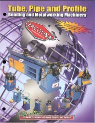
E RA E E DI G CART<br />
1.8 1.5<br />
1.8<br />
4.1 3.2<br />
4,4 2.9<br />
4.4<br />
7.4<br />
6.1<br />
7.7<br />
9.5<br />
61.7 45.8<br />
11.2<br />
85.2 63.6<br />
48.8<br />
13.1<br />
110.0<br />
86.2<br />
70.0<br />
16.9<br />
138.0 110.0 93.0<br />
165.0 137.0 104.0<br />
• The tonnages indicated in boxes are for die<br />
openings 8 times thickness of metal.<br />
• 5/16" and over die openings should be 10 times<br />
metal thickness. Larger openings greatly reduce<br />
tonnages required.<br />
• With an 8 to 1 die ratio the inside radius of a right<br />
angle bend is approximately equal to the thickness<br />
of the material. Bending pressures for other<br />
metals, as compared to mild steel on chart, are as<br />
follows:<br />
- soft brass - 50% of pressure shown<br />
- soft aluminum - 50% of pressure shown<br />
- aluminum alloys heat-treated - same as steel<br />
- stainless steel-50% more than steel<br />
- chrome molybdenum - 100% more than steel.<br />
• All of the above bending pressures are nominal<br />
and represent average conditions. These values<br />
are dependent upon the radii ofthe dies, theyield<br />
strength of the material, the temper of the<br />
material,the direction of the rolling strains, etc.<br />
THEREFORE A SAFETY FACTOR OF AT LEAST<br />
20% SHOULD BE PROVIDED IN SELECTING A<br />
PRESS FOR A GIVEN JOB.