e-Series Clip Installation Instructions 10-2010A - Pandrol USA
e-Series Clip Installation Instructions 10-2010A - Pandrol USA
e-Series Clip Installation Instructions 10-2010A - Pandrol USA

Create successful ePaper yourself
Turn your PDF publications into a flip-book with our unique Google optimized e-Paper software.
<strong>Pandrol</strong> Brand Rail Fastenings<br />
e-<strong>Series</strong> <strong>Clip</strong> <strong>Installation</strong> <strong>Instructions</strong><br />
Wood Tie <strong>Installation</strong>:<br />
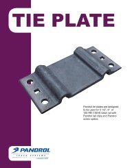
Components for one rail seat on a wood tie consists of a <strong>Pandrol</strong> rolled steel tie<br />
plate, two e-series clips (e-2055), and screw spikes. The number of plate<br />
fasteners required will depend upon the application.<br />
The tie plate should be positioned on a new or freshly adzed tie, before the rail is<br />
laid in the plate and the holes are drilled for the plate hold down fasteners. The tie<br />
plate is canted and should be placed so that the cant runs towards the center of the<br />
tie. You should notice that the taller, raised heel seat is the field side of the plate.<br />
It is recommended that the tie is tamped before clip installation.<br />
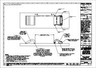
With the tie plate centered, drill the pilot hole for the screw spike.<br />
For a <strong>Pandrol</strong><br />
15/16" screw spike the hole should be 3/4" diameter and six inches deep from the<br />
top of the tie plate. A visual check<br />
should be made to insure that the plate<br />
fasteners are all the way down and thee tie plate is<br />
tight against the tie.<br />
The e-2055 clip is installed from the right hand side of the tie plate as you face the<br />
rail, with the "toe" or open end of the clip on the foot of the rail.<br />
The e-series clip<br />
can then be started by hand or with a few taps from a sledge hammer.<br />
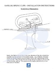
The clip<br />
should be driven until there is approximately 3/8" gap (about the diameter of a<br />
pencil) between the edge of the tie plate and the inner edge of the rear arch of the<br />
clip. The e-2055 clip can also be mechanicallyally installed to the above specifications.<br />
cations<br />
There are several types of equipment available a le for this purpose.<br />
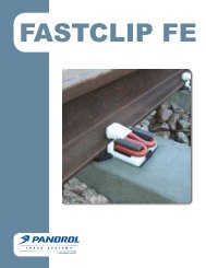
Concrete Tie <strong>Installation</strong>:<br />
Concrete tie components for one rail seat consists of the following: a tie pad, two<br />
insulators and two e-series clips.<br />
The correct <strong>Pandrol</strong> shoulders are already<br />
embedded in the tie by the concrete tie manufacturer. If questions concerning the<br />
assembly components onents arise, please contact <strong>Pandrol</strong> <strong>USA</strong>.<br />
Rev. 01-2011
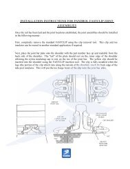
First,placethepadintherailseataftermakingsurebotharecleanandfreeofdebris.<br />
Next install the rail and tamp the tie. The insulators are installed next (one each side<br />
of the rail) making sure the insulator is fully seated against the base of the rail. Then<br />
start the e-2055 clip from the right side of the shoulder by hand or set with a few taps of<br />
a sledge hammer. The clip is fully driven when there is approximately 3/8" gap between<br />
the edge of the shoulder and the rear arch of the clip. As with the wood installation, the<br />
e-series clip can be installed by mechanical means.<br />
When using a Deep Post style insulator make sure it seats securely on the rail base and<br />
into the recession in the pad. The Deep Post Pad must be placed on the tie with the<br />
thin membrane resting on the tie and the open area facing up. The Deep Post Insulator<br />
extends below the base of the rail and sits on the pad membrane. (If using a "sandwich<br />
pad" the membrane will rest on the steel plate.) Caution should be taken never to mix<br />
Deep Post Insulators with standard pads. Although standard insulators will work with<br />
Deep Post Pads, it is not recommended since the pad may try to shift.<br />
General:<br />
The shipping tag supplied with<br />
every bag of clips illustrates a properly<br />
installed clip on wood and concrete ties.<br />
<br />
<br />
<br />
<br />
<br />
<br />
When installing or removing clips a sledge hammer should be used instead of a<br />
spikingi<br />
maul because of the larger striking area.<br />
A quick visual check for proper clip installation is tohave the end of<br />
the clip toe<br />
even or ¼” past the edge of the tie plate or shoulder.<br />
e-series clips ending in an odd number, example e-2055 are right hand driven.<br />
<strong>Clip</strong>sendinginanevennumber,examplee-2056arelefthandapplied.<br />
exampl<br />
e e-2056 ar<br />
e left<br />
d<br />
<strong>Clip</strong>s can be installed and removed either manually or mechanically.<br />
Never use Deep Post Insulators with standard tie pads.<br />
Consult <strong>Pandrol</strong> <strong>USA</strong> for further details or specifications.