Seite 1 - ISOBRUGG
Seite 1 - ISOBRUGG
Seite 1 - ISOBRUGG

Create successful ePaper yourself
Turn your PDF publications into a flip-book with our unique Google optimized e-Paper software.
Prefabricated<br />
SCP-Steel Cased Pipe<br />
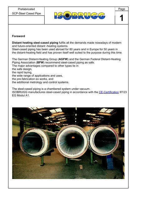
Foreword<br />
Distant heating steel-cased piping fulfils all the demands made nowadays of modern<br />
and future-oriented distant -heating systems.<br />
Steel-cased piping has been used abroad for 80 years and in Europe for 50 years in<br />
the distant-heating field and has proven itself well suited to the purpose during this time.<br />
The German Distant-Heating Group (AGFW) and the German Federal Distant-Heating<br />
Piping Association (BFW) recommend steel-cased piping as safe.<br />
The major advantages compared to other types lie in<br />
the safe design,<br />
the rapid laying,<br />
the wide range of applications and uses,<br />
the pre-fabrication ex works, and<br />
the additional metrology and control systems.<br />
Page<br />
The steel-cased piping is a chambered system under vacuum.<br />
<strong>ISOBRUGG</strong> manufactures steel-cased piping in accordance with the CE-Certification 97/23<br />
EG Modul A1.<br />
1
Prefabricated<br />
SCP-Steel Cased Pipe<br />
Applications<br />
<strong>ISOBRUGG</strong> steel-cased piping is suitable for use with all the media, temperatures,<br />
piping dimensions and pressure stages standard in distant heating and cooling<br />
depending on the piping materials and sidewall thickness. In addition, it is also used<br />
in industry as product piping.<br />
Standard applications warm water<br />
up to +200C hot water<br />
domestic hot water<br />
thermal oil<br />
condensate<br />
High temperatures steam<br />
up to +400C hot air and gases<br />
Low temperatures chemical products (safety piping)<br />
to -30C cooling water, refrigeration<br />
Isobrugg steel-cased piping is excellent for<br />
difficult ground conditions<br />
wet ground<br />
subsidence-endangered areas<br />
stream crossings (drains)<br />
road crossings<br />
for roadwork's and under concrete<br />
surfaces<br />
transport piping<br />
Special uses of steel-cased chambered piping are: laying where this is subject to<br />
WHG § 9 and as safety piping in accordance with TRbF and VbF.<br />
Steel-cased piping dimensions and design data<br />
Carrier pipe DIN 25 to DN 1200<br />
Temperatures up to 400 C<br />
Special tailored types on request<br />
Pressure stages up to PN 64<br />
Page<br />
2
Prefabricated<br />
SCP-Steel Cased Pipe<br />
INDEX OF CONTENTS<br />
Product Description - System description<br />
- Technical Specifications<br />
Components - Standard lengths<br />
- Support<br />
- Anchor<br />
- Bellows-type termination<br />
- Wall bushing<br />
- Bends<br />
- T-joints<br />
- Reducers<br />
- Compensating exapansion elements<br />
- Steel shaft<br />
Accessories - Cathodic corrosion protection<br />
- Insulating flanges<br />
- Vacuum appliances<br />
- Vacuum pressure monitoring devices<br />
Design - Technical Requirements for fabrication<br />
- Sample sectional drawing<br />
- Steel casing selection table<br />
- Selection of insulation material thickness<br />
- Determination of casing dimensions<br />
- Table of heat expansion<br />
- Seamless inner pipe table<br />
- Welded inner pipe table<br />
- Steel-cased piping selection table<br />
- Natural expansion tolerance<br />
- Prestressing<br />
Page<br />
3
Prefabricated<br />
SCP-Steel Cased Pipe<br />
System Description<br />
Steel-cased piping has been field-proven over decades as a “steel-in-steel” piping system for<br />
laying direct in the ground, suitable for transporting distant heat, steam, condensate and other<br />
media.<br />
Both the straight special units up to 16 metres in length and all the system-typical components<br />
such as bends, junctions, anchors, supports, etc. are pre-fabricated ex works. This means<br />
greater safety by comparison with on-site assembly.<br />
Steel-cased piping is suitable for all the application areas and operating conditions met<br />
in practise, but especially for extremely high temperatures and pressures.<br />
Strictly project-related pre-fabrication ensures the economic relationship of production costs to<br />
operating needs. The choice of carrier piping specification, determination of insulation<br />
thickness and calculation of the casing nominal dimensions is always dependent on the<br />
specific operating conditions.<br />
The gas- and water-tight welding of the carrier piping to the casing piping in shaft and con-<br />
struction bushings is standard in steel-cased piping. It is the pre-condition for the evacuation<br />
of the space between the carrier and casing piping. This evacuation ensures removal of any<br />
residual damp. At the same time, the insulation of the piping is greatly improved.<br />
Vacuum maintenance and monitoring ensures excellent means of checking that the system<br />
does not leak. This ensures safety during the operation of the system.<br />
Further safety measures are the carefully project-related cathodic corrosion-proofing preven-<br />
ting external corrosion of the casing piping. In addition, electronic monitoring devices warn<br />
immediately of any damp entering the insulation.<br />
The robust tailored design on the basis of long experience in building and using this piping sy-<br />
stem makes steel-cased piping a top-quality, safe transport means for all temperatures.<br />
Page<br />
4
Prefabricated<br />
SCP-Steel Cased Pipe<br />
Technical<br />
Specification<br />
Material-specific standard components<br />
Casing piping<br />
Longitudinally or spirally welded steel piping, dimensions according to DIN 2458, ISO,<br />
Material St. 37.0 or St. 52.0 (WA or WB)<br />
Delivery conditions DIN 1626 (dated October 84) Seal of approval DIN 50049-2-2 or 3.1B<br />
Welding bevelling per DIN 2559, Page 1, Code Number 21 or 22<br />
Exterior protection<br />
Page<br />
a) Bituminous sheathing for increased temperatures per DIN 30673, Type A 5.5 G, double-with carrier layer of<br />
glass fibre cloth.<br />
b) PE-coated per DIN 30670 N, type n or v, electrical puncture strength 20 kV, peel resistance 35 N.<br />
Carrier piping<br />
a) Seamless steel piping per DIN 2448, ISO, Material St. 37.0 or St. 52.0 S, DIN 1629/EN with welding<br />
bevelling per DIN 2559 Page 1 Code No. 21 or 22. Material approval per DIN 50049-3.1B including circular<br />
seams in ex works special units.<br />
b) Seamless piping of heat-resistant steel (boiler piping) per DIN 17175 St. 35.8, Materials approvals per DIN<br />
50049-3.1 B, welding bevelling per DIN 2559, Page 1, Code No. 21 or 22.<br />
c) Welded piping, longitudinal or spiral weld, dimensions per DIN 2458/EN 10217, ISO, delivery conditions per<br />
DIN 1626, St. 37.0 (WA or WB), Material approval per DIN 50049-3.1.B, welding bevelling per DIN 2559, Page<br />
1, Code No. 21 or 22.<br />
Heat insulation<br />
Make-up pieces of high-silicate mineral wool fibre, SiOs content about 60% or make-up pieces of rock wool<br />
fibre, water resistant, temperature resistant 300°C, thermal conductivity 0.035 W/(m x K) (20C), non-flammable<br />
per DIN 4102/A1.<br />
Insulating make-up pieces fastened to carrier piping with stainless steel bands.<br />
Guide and friction supports<br />
Guide supports are roller- or friction-bearing supports. Rollers made of material GG 24 or St. 37-2k, roller bolts<br />
of St. 37-2k or stainless steel 1.4301, screws of heat-resistant material. on operating temperature, dollies for<br />
reducing thermal transfer made of suitable VA materials. To stop the heat flow, the support make-up pieces are<br />
secured to the mediumcarrying piping with compressed fibre strips.<br />
Bends<br />
a) Carrier piping bends<br />
Analogous to DIN 2605 or 2606 Material per carrier piping specs. Welding seams non-destructively tested to<br />
DIN 5411 using X-rays or gamma-rays.<br />
b) Casing piping bends<br />
Made in segments, radius per carrier piping. Material per piping specs. Weld seams non-destructively tested<br />
per DIN 54111. Tested for 100% leak-proofing. In the segment welding seam areas, insulation protection with<br />
fire-resistant material to prevent burning during welding.<br />
Anchor<br />
a) Free of thermal bridging, for taking up carrier piping reaction forces or bellows expansion reaction forces.<br />
Installed in special units ex works. Consists of 2 steel rings, US-tested, reinforced with plating and welded to<br />
carrier piping. A US-tested reinforced steel ring as casing piping disc welded to casing piping. KV3 wedges<br />
(asbestos-free) installed as force-transmitting intermediate support to interrupt heat flow and for electrical nent<br />
is subjected only to pressure stress.<br />
b) Intermediate anchor consisting of a plate on the casing piping, two plates on the carrier<br />
piping and pressure-fast intermediate supports isolating heat flow.<br />
5
Prefabricated<br />
SCP-Steel Cased Pipe<br />
Technical<br />
Specification<br />
End caps<br />
Page<br />
Vacuum-tight end caps between carrier and casing piping with simultaneous taking up of the<br />
axial movement of the carrier piping.<br />
a) Bellows-type termination<br />
Expansion joint of material 1.4541, single- or multi-walled.<br />
Expansion take-up max. 30 mm, PN 16.<br />
Reduction of carrier piping temp. via bellows length.<br />
b) MS bellow termination<br />
Expansion joint of material St. 37<br />
Expansion take-up max. 6 mm<br />
Pre-fab installation ex works in special units with vacuum and evacuation connections.<br />
Wall bushing<br />
Wall bushing consisting of sleeving piping with collar, prodoral coated, steel cased piping<br />
guided in collaring with friction slides, annular area sealed with rubber gasket. Electrically<br />
insulated.<br />
Connection between casing piping and sleeve MS bellow or heat-shrunk hosing. Complete<br />
special unit ex works. If necessary, annular space filled with suitable bituminous mass.<br />
T-branch<br />
Pre-fab and installed in a special unit ex works. Steel cased piping junctions - welding<br />
saddle per DIN 2618<br />
Medium-carrying ping junction - T-piece per DIN 2615 or Weldolet.<br />
Plant monitoring<br />
Specially developed automated warning and location metrology and monitoring system to<br />
permanently monitor dampness in the entire STEEL-CASED PIPING network using the<br />
resistance measurement method.<br />
Evacuation<br />
Evacuation of the casing piping after completion and commissioning using a mobile vacuum<br />
motor to remove all damp from the insulation and the casing piping.<br />
Services available<br />
Planning and engineering<br />
a) Pipeline design plans<br />
b) Detail plans<br />
c) Piping construction engineering calculations<br />
d) Metrology documentation, system monitoring/cathodic corrosion protection<br />
e) Evacuation documentation<br />
f) Pressure increase testing documentation / on demand<br />
6
Prefabricated<br />
SCP-Steel Cased Pipe<br />
Components<br />
Steel-cased piping standard lengths (SL)<br />
with single-pipe design (SINGLE-PIPE CONDUIT)<br />
1 Carrier piping (CARRIER PIPING)<br />
2 Thermal insulation (IS)<br />
3 Casing piping (CASING PIPING)<br />
4 CASING PIPING coating (PEN), (PEV), (BI)<br />
5 Alignment support (slide or roller) LA)<br />
Page<br />
7<br />
Min. span, support intervals “X” dependent on nominal<br />
carrier piping dimensions<br />
CARRIER PIPING DN 20 - 25 X = 2.00 m<br />
CARRIER PIPING DN 32 - 40 X = 2.40 m<br />
CARRIER PIPING DN 50 - 65 X = 3.00 m<br />
CARRIER PIPING DN 80 - 125 X = 4.00 m<br />
CARRIER PIPING DN 150 - 500 X = 6.00 m<br />
Support (alignment support) design dependent on load<br />
and operating mode.
Prefabricated<br />
SCP-Steel Cased Pipe<br />
Components<br />
The bearings are due to a functional guidance and support of the<br />
termal isolated carrier pipe inside the casing pipe.<br />
to DN 65 I RF from DN 80<br />
Page<br />
8
Prefabricated<br />
SCP-Steel Cased Pipe<br />
Components<br />
Interim anchor (ZFP) in SINGLE-PIPE CONDUIT<br />
An interim anchor is a connecting piece between the carrier and casing piping. It has<br />
the purpose of taking up the carrier piping reaction forces and diverting them to the<br />
casing piping and, from there, to the ground.<br />
The anchors are installed in the special units ex works.<br />
Page<br />
The Isobrugg steel-cased piping anchors are so designed that the overall design prevents<br />
unacceptably high carrier and casing piping temperatures.<br />
Calculation of carrier piping reaction forces effects and the design and dimensioning of<br />
anchors is project-related and dependant on the specific Isobrugg steel-cased piping.<br />
Interim anchor “CASING PIPING” in single-pipe conduits<br />
An anchor with torsion-resistant securing device/s is installed when compensators and<br />
cold or thermal prestressing are used.<br />
Diagram of an interim anchor<br />
Principle sketch of interim anchor<br />
9
Prefabricated<br />
SCP-Steel Cased Pipe<br />
Components<br />
Bellows-type terminations are gas- and vacuum-tight caps permitting axial movement<br />
of the carrier piping.<br />
Bellows-type terminations are pre-fabricated ex works and installed in special units.<br />
1 Carrier pipe<br />
2 Thermal insulation<br />
3 Casing pipe<br />
4 Casing pipe plate<br />
5 Carrier pipe plate<br />
6 Axialbellow<br />
7 Vacuumconnection<br />
8 Drainplug<br />
Page<br />
10
Prefabricated<br />
SCP-Steel Cased Pipe<br />
Components<br />
Wall bushings (MD) for single<br />
Isobrugg steel-cased piping wall bushings are so designed as to be project-related<br />
and so that<br />
1. the wall is not damaged by the longitudinal motion of the casing piping;<br />
2. neither ground nor surface water can enter the building or shaft;<br />
3. the bushings can take up minor axial movement of casing piping.<br />
They are not suitable for high loading with earth or for subsidence's. Earth covering in<br />
the shaft area, the sand base and piping sand covering are to be carried out in accor-<br />
dance with the appropriate DIN, AGFW and VOB Part C standards and to be so tam-<br />
ped down that subsidence is impossible.<br />
The bushings are installed on the special units ex works and then delivered to the site.<br />
Wall entry with mild steel bellow<br />
[Back] [Next Page]<br />
Page<br />
11
Prefabricated<br />
SCP-Steel Cased Pipe<br />
Components<br />
Steel cased pipe-elbow (B) at IRF<br />
Page<br />
12
Prefabricated<br />
SCP-Steel Cased Pipe<br />
Components<br />
T-branches are pre-fabricated ex works<br />
and installed in a special unit.<br />
Page<br />
13<br />
T-branch, single-pipe conduit<br />
Single-conduit outlet<br />
T-piece per DIN 2615 or Weldolet<br />
Casing pipe outlet<br />
Saddle piece per DIN 2618<br />
Parallel outlet, single-pipe conduit<br />
Carrier pipe outlet<br />
T-piece per DIN 2615<br />
Casing pipe outlet<br />
Saddle pieces per DIN 2618
Prefabricated<br />
SCP-Steel Cased Pipe<br />
Components<br />
Diameter changes in the carrier piping and casing piping are compensated for by<br />
concentric reducing pieces per DIN 2616. These are installed ex works.<br />
Casing piping reducer (MRR)<br />
Carrier pipe reducer (IRR)<br />
Single-pipe conduit design<br />
Carrier piping reducer (IRR)<br />
Twin-pipe conduit design<br />
Page<br />
14
Prefabricated<br />
SCP-Steel Cased Pipe<br />
Components<br />
Kompensator Dehnungselement (KDE)<br />
expansion compensation<br />
by internal axial bellows<br />
with extended casing pipe<br />
1 Carrier pipe<br />
2 Casing pipe<br />
3 Insolation<br />
4 Axial bellow<br />
5 Track guide<br />
6 corrosion coating<br />
7 Anchor<br />
8 Casing pipe extension<br />
Page<br />
15
Prefabricated<br />
SCP-Steel Cased Pipe<br />
Components<br />
Steel shaft with access, designed for an<br />
operating loading of up to 60 SLW, in-<br />
cluding pump sump, inbuilt ladder, shaft<br />
ventilation, corrosion-proofing paint within,<br />
exterior corrosion-proofing of reinforced<br />
bitumen sheathing in tropical quality per<br />
DIN 30673 Type A, 5.5 G with double<br />
carrying layer of glass fibre matting,<br />
electrical puncture strength 20,000 V,<br />
with piping connection pieces for<br />
inlet and outlet piping, completely pre-<br />
fabricated ex works.<br />
Proof of static strength supplied on de-<br />
mand.<br />
Ballast concrete to hold shafting safely in<br />
place is the client’s responsibility.<br />
Page<br />
16
Prefabricated<br />
SCP-Steel Cased Pipe<br />
Accessories<br />
When constructing and operating cathodic corrosion-proof equipment, the following<br />
pre-conditions must be met:<br />
- good electric conductivity throughout;<br />
- perfect non-ageing piping sheathing of PE or bitumen without mechanical damage;<br />
- the casing piping to be protected must not have any electrical contact<br />
to non-system parts or any ancillary installations.<br />
Page<br />
17<br />
Electrical insulation from ancillary low-impedance equipment in shafting or from interconnecting<br />
stations of the piping to be protected is carried out by installing insulating flanges.<br />
Insulating flanges consist of a flange pair electrically insulated from one another with welding<br />
socket ends and internally coated piping supports as insulant.<br />
Note that different makers have different designs.<br />
Design and installation of cathodic corrosion-proofing equipment for STEEL-CASED distant<br />
heat PIPING is part of our service and product range.<br />
After installation and commissioning, a metrology protocol on testing and acceptance of the<br />
equipment is drafted.
Prefabricated<br />
SCP-Steel Cased Pipe<br />
Accessories<br />
Cathodic corrosion proofing of STEEL-CASED PIPING<br />
Cathodic protection of steel piping laid in the ground is state-of-the art nowadays as active<br />
corrosion protection for steel-cased distant heat piping together with passive corrosion<br />
protection (PE or bituminous sheathing of the steel-cased piping to DIN standards).<br />
This type of plant is required to protect steel-cased piping:<br />
1. in corrosive soil, i.e. where soil resistance values are equal to or less than 10,0000 Ohm cm;<br />
2. in pipelines with greatly varying such values, i.e. differences equal to or larger than<br />
10,0000 Ohm cm;<br />
3. in areas endangered by groundwater, and<br />
4. in areas possibly subject to stray current.<br />
Pre-conditions for our guarantee against corrosion of exterior piping protection surfaces<br />
Please note DIN 30676, “Planning and use of exterior surface cathodic corrosion protection”.<br />
Page<br />
18<br />
How such equipment functions can be seen in the diagram. The cathodic protective current IS is<br />
supplied by a rectifier connected to the mains. The current to the surface to be protected is via<br />
an external current anode. This is normally a Fe-Si sited in the earth at a set distance of around<br />
5 m from the piping in a coke bed.<br />
The number and arrangement of the Fe-Si anodes depends on the protective current needed<br />
and hence on the piping surface to be protected as well as the specific soil resistance.<br />
INSULATING FLANGE<br />
BRAUNSTAHL insulating flanges are adherent<br />
flange connections pre-mounted and tested for<br />
electrical penetration resistance as standard.<br />
The standard model consists of 2 welding neck<br />
flanges, 2 gaskets (flat or O-ring), 1 insulating<br />
ring, nuts and bolts, insulating and steel annular discs.<br />
Only insulating materials with high electrical pe-<br />
netration resistance and good dielectric charac-<br />
teristics are used (DIN 7735 standard).<br />
O-ring gaskets of non-ageing paracril or other<br />
special materials only are used.<br />
Metallic materials are selected on the basis of<br />
technical conditions of supply or the correspon-<br />
ding German and foreign standards and regulati-<br />
ons.<br />
The standard design requires dis-assembly be-<br />
fore welding into the pipeline.
Prefabricated<br />
SCP-Steel Cased Pipe<br />
Accessories<br />
Pre-condition for the guarantee under our Conditions of Sale is the<br />
evacuation<br />
of the steel-cased piping by an <strong>ISOBRUGG</strong> technician.<br />
During construction of STEEL-CASED PIPING, atmospheric damp usually<br />
penetrates the insulating material and condensate builds up on the casing.<br />
Once installation is complete, evacuation of the annular spacing with the aid of a<br />
mobile vacuum plant sucks out all the damp in the piping system as a steam-air<br />
mixture and the pressure is reduced to around 1 mbar.<br />
A pressure increase monitor permits leak rates to be checked constantly and<br />
hence inform on whether the system remains leak proof.<br />
Apart from these two functions, the heat loss can also be considerably reduced if<br />
the distant heating piping is under constant vacuum<br />
The mobile vacuum appliance consists of a vacuum pump, a refrigerating<br />
machine, a condensator, a fluid collector with automatic rapid emptying and an oil<br />
separator. The client must make 380 V AC current and a 32 A Euro plug<br />
available to operate the appliance.<br />
Page<br />
19
Prefabricated<br />
SCP-Steel Cased Pipe<br />
Accessories<br />
<strong>ISOBRUGG</strong> Vacuum leat detection with alarm montion<br />
Principle sketch of permanent leak detection system<br />
Page<br />
20
Prefabricated<br />
SCP-Steel Cased Pipe<br />
Planning<br />
Page<br />
21<br />
Technical requirements for fabrication<br />
Please note: works to be carried out in conjunction with the technical code and the material<br />
specification for the fabrication of steel-cased piping and also the rules for installation;<br />
codes of practice and rules for civil works such as DIN 18300, DIN 4033, DIN 4124;<br />
as well as the rules for the prevention of accidents. All dimensions, especially angular measures,<br />
datum's, levels and trench profiles are to be checked prior to commencement of, and during, works.<br />
Notify <strong>ISOBRUGG</strong> immediately in the event of deviations. When crane-handling steel-cased piping, use<br />
textile slings only. In order to prevent damage to the external coating, use felt pads at support points<br />
during transport and intermediate storage. Only welders holding the RI certificate (DN 8560) or<br />
recognised equivalents may be used. Where indicated, carrier pipe is to be cold sprung the required<br />
distance as shown on drawing. Transport locking elements may only be removed after aligning and tack<br />
welding carrier piping. Within the area of site joints access holes as shown on the civil works data sheet<br />
are to be provided prior to laying and backfilling. External coating of each unit is to be Holiday-tested<br />
with 25 kV. The SCP units are numbered sequentially and marked accordingly at their ends. Each unit<br />
carries the marking, “oben”, denoting the twelve o’clock position. The 12 o’clock position<br />
of the carrier piping is marked by a stamped figure “0”. When lining-up the units for welding, both<br />
marking must be at the top in the 12 o’clock position.<br />
I RF Einrohrführung Single-pipe conduit<br />
II RF Einrohrführung Twin-pipe conduit<br />
CARRIER PIPING Innenrohr Carrier pipe<br />
CASING PIPING Mantelrohr Casing Pipe<br />
IS Isolierdicke Insulation thickness<br />
VL Vorlauf Flow<br />
RL Rücklauf Return<br />
D Dampf Steam<br />
K Kondensat Condensate<br />
BW Brauchwasser Domestic hot water<br />
Z Zirkulation Circulation<br />
Betriebsdaten: Operating data<br />
Betriebsdruck Operating pressure 9 bar Auslegungsdruck Design pressure 25 bar<br />
Operating pressure 14 bar " " " " "<br />
Operating pressure 21 bar " " " " "<br />
Temp.- 210 C ( 1 = 2.5 mm/m<br />
LA Axiallager Alignment support ∆ L Innenrohrausdehnung Linear expansion<br />
of carrier pipe<br />
LP Lagerplatte Support plate ∆ I Ausdehnungskoeffizient Linear co-effcient<br />
of expansion<br />
ZF Zwangsführung Track guide kon Konzentrisch Concentric<br />
FP Festpunkt Intermediate anchor ex. Exzentrisch Eccentric<br />
MD Mauerdurchführung Wall entry MRR Mantelrohrreduzierung Casing reducer<br />
AKV<br />
AK<br />
Axialkomp.-Verschluß Bellow type termination IRR<br />
Axialkomp. im Innenrohr Axial Bellow TA<br />
Innenrohrreduzierung<br />
T-Zweig<br />
Carrier pipe<br />
reducer<br />
T-branch<br />
B Bogen Bend BVS Verschlußkappe(CARRIER<br />
L Linse MS Bellow<br />
PIPING+CASING PIPING)<br />
BE Baueinheit<br />
BV Baustellenverbindung<br />
Capped ends<br />
Special unit<br />
Site joint<br />
Mantelrohr - Halbschale<br />
Casing pipe<br />
Mantelrohr beiziehen<br />
makeup piece<br />
Casing pipes<br />
abutted
Prefabricated<br />
SCP-Steel Cased Pipe<br />
Planning<br />
Page<br />
22
Prefabricated<br />
SCP-Steel Cased Pipe<br />
Planning<br />
Steel-cased piping selection table single-pipe conduits (IR)<br />
Page<br />
23<br />
Casing pipe sizes for differing temperature ranges dependant on carrier pipe dimensions<br />
and thermal insulation (IS)<br />
A minimum ring gap of 20 mm is included in the table.<br />
Double-check the casing pipe size in the expansion joint areas.
Prefabricated<br />
SCP-Steel Cased Pipe<br />
Planning<br />
Thermal insulation selection table (standard)<br />
Economic thicknesses of mineral wool make-up pieces for various piping dimensions<br />
and operating temperatures.<br />
Given details of the ground conditions, lambda values for the soil, average soil tem-<br />
perature, the dimensions of the carrier and casing piping, medium temperature and<br />
corresponding insulation thickness, the heat loss of Isobrugg steel-cased piping can<br />
be calculated.<br />
For larger projects and lengthier transport piping, especially at high operating tempe-<br />
ratures, steel-cased piping systems should be operated with permanent vacuum.<br />
The insulation thicknesses in the table can then be reduced without affecting heat<br />
loss.<br />
Page<br />
24
Prefabricated<br />
SCP-Steel Cased Pipe<br />
Planning<br />
Determination of the casing piping di-<br />
mensions in single-pipe conduits(IR)<br />
A ring gap of at least 20 mm is essential to<br />
ensure the steel-cased piping can be put<br />
together easily. The casing piping in-terior<br />
diameter must therefore be at least 40 mm<br />
greater than the external diame-<br />
ter of the thermal insulation. This ring<br />
gap is also important to the emptying of the<br />
casing piping and the rapid evacua-tion and<br />
drying of the thermal insulation<br />
as well. At the same time, correct casing<br />
piping dimensions tallying with the ring gap<br />
size permit carrier pipe movement<br />
of at least 2 x 20 mm. Expansion greater than<br />
this can only be taken up given lar-<br />
ger casing piping.<br />
Determination of the casing piping dimensions<br />
Examble: Carrier pipe dimension = DN 150 (168.3 x 4.0)<br />
Carrier pipe temperature = 150 C<br />
Insulation thickness per selection table = 70 mm<br />
Casing piping dimensions determination: CARRIER PIPING DN 150 = 168 mm<br />
Insulation 2 x 70 mm = 140 mm<br />
Ring gap 2 x 70 mm = 40 mm<br />
= 348 mm<br />
Page<br />
25<br />
Casing piping size to select: DN 350.<br />
In the event of directional alteration, longitudinal expansion of the carrier piping is restricted<br />
with this choice. These dimensions are applicable for expansion take-up of max. +/- 19.8<br />
mm, totalling 39.6 mm, at 50% pre-stress of the carrier piping. This governs the maximal<br />
expansion length (space between anchor and expansion compensators).<br />
At a temperature of 150 C, the longitudinal expansion factor = 1.88 mm/m.<br />
∆ L total at 50% pre-stress = Total expansion<br />
Longitudinal expansion factor<br />
= 39.6 mm<br />
1.88 mm/m = 21.07 m.<br />
This casing piping size is therefore only suitable for short piping distances.
Prefabricated<br />
SCP-Steel Cased Pipe<br />
Planning<br />
Table heat expansion for steel pipes<br />
Steel pipes material St. 37.0 S and St. 52. thermal expahsion coefficient ∆ L in<br />
mm/m at a reference temperatur of 10°C and operating temperatures t in °C<br />
Page<br />
26
Prefabricated<br />
SCP-Steel Cased Pipe<br />
Planning<br />
Carrier pipe data table seamless steel pipes<br />
acc DIN 2448/EN 10216, material St. 37.0 S - Standard<br />
Page<br />
27
Prefabricated<br />
SCP-Steel Cased Pipe<br />
Planning<br />
Carrier pipe data table welded steel pipes<br />
acc DIN 2448/EN 10217, material St. 37.0 WA or WB, Standard.<br />
WA = welding valmcl 0,9<br />
WB = welding valmcl 1,0<br />
Page<br />
28
Prefabricated<br />
SCP-Steel Cased Pipe<br />
Planning<br />
Casing piping table (standard)<br />
Page<br />
29<br />
Casing piping dimensions per DIN 2458/EN 10217 in St. 37.0 WA material - works certification<br />
per DIN 50049-2.2<br />
Insofar as thicker walls may be needed for construction engineering reasons, e.g.<br />
due to inadequate covering, larger casing piping can be used without hesitation.
Prefabricated<br />
SCP-Steel Cased Pipe<br />
Planning<br />
Page<br />
30<br />
One means of increasing expansion length results from the extension of the casing<br />
piping in the expansion bend areas. The expansion of casing piping DN 350 to casing<br />
piping DN 400 results in an increase in ring gap from 19.8 mm to 45.2 mm and in expansion<br />
take-up to a total of 90.4 mm, which means the expansion length can be in-<br />
creased to about 40 m instead of the former approximately 20 m.<br />
Depending on pipeline profile, casing piping extension of up to four times the dimen-<br />
sions is possible, so that carrier piping expansion at 50% pre-stress of up to 200 mm<br />
can be compensated for.<br />
The natural expansion compensators such as U- Z- and L-bends can also be repla-<br />
ced with full-protection bellows-type axial compensators, whereby the normal casing<br />
piping usually need not be changed.
Prefabricated<br />
SCP-Steel Cased Pipe<br />
Planning<br />
Steel-cased piping compensatory expansion elements<br />
Page<br />
31<br />
Insofar as natural expansion compensators such as U-, L- or Z-bends are inadequa-<br />
te, bellows-type joints can be substituted. These are also welded to the carrier piping<br />
ex works and installed in the steel-cased piping with anchors and guide supports ac-<br />
cording to the maker’s regulations. Two expansion elements can be installed in any<br />
one special unit, i.e. one intermediate anchor and two compensators with track gui-<br />
des as per system diagram can be installed to take up the expansion from both di-<br />
rections like a U-bend expansion compensator. With special track guides, bellows-<br />
type axial compensators can also be used with twin-pipe conduits.<br />
Only so-called “FULLY PROTECTIVE COMPENSATORS” with external protective pi-<br />
ping, interior guide tubing, lift limitations devices, pre-stress safety devices, torsion<br />
safety devices and their own guide devices are suitable for installation in a steel-ca-<br />
sed piping system.<br />
The service life of a compensator is dependant on temperature, pressure, load, load<br />
change intervals, fluid medium hammering, corrosion and installation errors.
Prefabricated<br />
SCP-Steel Cased Pipe<br />
Planning<br />
Page<br />
32