2 - SMG - Slotted Microwave Guide - VAHLE, Inc
2 - SMG - Slotted Microwave Guide - VAHLE, Inc
2 - SMG - Slotted Microwave Guide - VAHLE, Inc

Create successful ePaper yourself
Turn your PDF publications into a flip-book with our unique Google optimized e-Paper software.
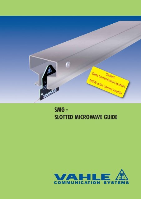
Safest<br />
Data transmission system<br />
NEW with carrier profile<br />
<strong>SMG</strong> -<br />
SLOTTED MICROWAVE GUIDE
TABLE OF CONTENTS<br />
1.Introduction<br />
Page<br />
Page<br />
1.1 General Description 3<br />
1.2 Areas of Application 4<br />
1.3 Features 5<br />
1.4 Application Examples 7<br />
1.5 Configuration 9<br />
2. Electronic Components<br />
2.1 <strong>SMG</strong> Transceiver 10<br />
2.2 <strong>SMG</strong> Antenna switch for<br />
Crossover function 11<br />
2.3 <strong>SMG</strong> Antenna switch for<br />
Bypass function 12<br />
2.4 Possible <strong>SMG</strong>- module combinations 13<br />
3.Mechanical Components<br />
3.1 <strong>SMG</strong>T Waveguide 15<br />
3.2 HF Connection 16<br />
3.3 HF Termination 17<br />
3. 4 Joint Splice Clamp 17<br />
3. 5 Waveguide Anchor Bracket 17<br />
3. 6 Support Bracket 18<br />
3. 7 Support Arm 19<br />
3. 8 Antenna trolleys 20<br />
3. 9 Antenna units 21<br />
3.10 Mobile Antennas (spare parts only) 22<br />
3.11 Special Antenna assembly 22<br />
3.12 HF cables with Accessories 23<br />
4.Configuration Support<br />
4. 1 Constructional Design of the<br />
<strong>SMG</strong> Waveguide 24<br />
4. 2 Configuration Example 26<br />
4. 3 Questionnaire 28<br />
5. Technical Description for Ordering 29<br />
6. Certification 33<br />
<strong>VAHLE</strong> Programm 36<br />
<strong>SMG</strong>-Data Transmission with <strong>VAHLE</strong> Conductor System for AS/AR warehouse<br />
2
1 INTRODUCTION<br />
1.1 General Description<br />
<strong>Slotted</strong> <strong>Microwave</strong> <strong>Guide</strong> - Data Transmission System<br />
The <strong>SMG</strong> data transmission system is highly suitable<br />
for automation applications as it transmits free<br />
of interference high rates of data to tracked machinery.<br />
<strong>SMG</strong> was originally developed by MBB (Messerschmitt-Boelkow-Blohm),<br />
now EADS, to transmit<br />
data to the magnetic levitation train traveling at<br />
speeds of up to 250 mph. <strong>VAHLE</strong> acquired this<br />
product by the end of 1994 and now has worldwide<br />
over 4000 installations successfully in operation.<br />
<strong>VAHLE</strong> has embarked on an extensive development<br />
program to increase the <strong>SMG</strong> application<br />
range. Presently there are already data interfaces<br />
available for the most commonly used bus<br />
systems.<br />
Heavy-duty construction makes it possible to<br />
install <strong>SMG</strong> in arduous and environmentally difficult<br />
locations; for instance a great number of <strong>SMG</strong><br />
waveguide systems are functioning reliably in steel<br />
mills and foundries.<br />
The <strong>SMG</strong> data transmission system operates<br />
economically already with single channel transmission<br />
and low data rates. Modular design easily<br />
expands the system to handle at relatively low cost<br />
medium and high data rates as well as multi-channel<br />
configurations upto 1000 m length. Circual<br />
systems from a diameter of 1,80 m could be made<br />
out of the <strong>SMG</strong>-profile and are suitable for the on<br />
page 6 mentioned features.<br />
When combined with <strong>VAHLE</strong> conductor systems<br />
for the current supply, <strong>SMG</strong> data transmission<br />
systems become a reliable high-performance<br />
component package capable of handling a wide<br />
variety of applications as demanded by current and<br />
future automation technology.<br />
3
1 INTRODUCTION<br />
1.2 Areas of Application<br />
Port Container Terminal<br />
Airport Cargo Terminal<br />
High bay warehouse with stacker crane<br />
Regatta track Duisburg<br />
The fail-safe and variable <strong>SMG</strong>-concept opens a wide range of applications:<br />
Crane installations<br />
- automatic cranes<br />
- portal cranes<br />
- container cranes<br />
Automated material handling systems<br />
- AS/AR warehouse<br />
- robotics<br />
- production lines<br />
- coke oven machinery<br />
Transit systems<br />
- people movers<br />
- automated feeder-lines<br />
Elevator systems<br />
- passenger elevators<br />
- inclinators<br />
Freight transfer<br />
- airport cargo<br />
- container terminals<br />
Security systems<br />
- mobile video transmission<br />
- target range<br />
Entertainment<br />
- parks & racetracks<br />
- stadiums & arenas<br />
4
1 INTRODUCTION<br />
1.3 Features<br />
The <strong>SMG</strong> – system is constructed for the transmission of digital, serial datas, as it is common usage in data<br />
comunication networks. The digital data transmission in mpeg 4-format through a ethernet interface (electronical<br />
& optical) is a standard application.<br />
Special transceivers (transmission-/receiving units) with interface modules for all popular bus systems prepare<br />
the digital-serial signals via frequency modulation.<br />
To transmit in full duplex two carrier frequencies with high band width at approx. 2.4 GHz are availble.<br />
The microwave signal pagates wihtin an slotted, hollow aluminum extrusion (waveguide) between the transceivers.<br />
A transparent structure, resp. the support of numerous data protocols simplify the integration of the<br />
<strong>SMG</strong> data transmission system into an existing bus system. If required, <strong>VAHLE</strong> can provide engineering and<br />
service support for this task.<br />
However, important features, due to the fact of a waveguide, the coexistence of other wifi systems<br />
(e.g. Bluetooth, ZigBee, WLAN) and the protection against sabotage and manipulation.<br />
The following characteristics distinguish <strong>VAHLE</strong> <strong>SMG</strong> data transmission technology:<br />
- No interference as microwave is completely<br />
contained by <strong>SMG</strong>T waveguide<br />
- Simple integration into existing bus systems<br />
and upgrade posibility is facilitated by modular<br />
design<br />
- Non-contact transmission technology offers<br />
maintenance free operation<br />
- Safety relatet transmission capability e.g.<br />
PROFISAFE, SafetyNET can be connected<br />
- <strong>SMG</strong>T directly combines with all <strong>VAHLE</strong> conductor<br />
systems and may be installed simultaneously<br />
- Multiple vehicles on one waveguide<br />
- Faultless transmission of high data rates, up to<br />
10 Mbit/sec.<br />
- Uninterrupted data transmission independent<br />
of operating speed<br />
- Large bandwidth allows full duplex transmission<br />
of six data channels simultaneously<br />
- Environment such as temperature, rain, fog,<br />
dust etc. does not degrade the quality of the<br />
transmission<br />
- Dynamically very efficient transceivers permit<br />
transmission up to 1000 m without amplification<br />
- <strong>SMG</strong> is also suitable for systems with curves,<br />
track switches, interruptions, etc.<br />
5
1 INTRODUCTION<br />
1.3 Features<br />
The <strong>SMG</strong> Data Transmission provides interfaces for all common databus systems as well as special interfaces<br />
for video, audio, control and emergency-stop signals. All interfaces are plug-in modules for easy adaption<br />
to the existing communication structure. A galvanized seperation of the interface signals is a standard of<br />
the <strong>SMG</strong>-data transmission.<br />
The following data interfaces are available:<br />
Interface maximum typical applications<br />
communication<br />
rate (kbit/s)<br />
TTY/20 mA 20 Sinec L 1-Bus, Programmable Unit,<br />
interface converter, communication processor<br />
RS 232 C 20 PC, scanner, scales, etc.<br />
RS 422 1.500 InterBus-S according to EN 50254 Vol. 2,<br />
point to point<br />
other 4-wire connection, measurement signal transmission<br />
InterBus - S 2000 InterBus - S communication via SUPI 3 OPC<br />
with optical and electrical connector<br />
RS 485 1.500 Profibus EN 50170 Volume 2<br />
DH 485 9,6 Allen-Bradley DH 485 - Databus<br />
A-B DH+ 57,6 Allen-Bradley Data Highway Plus<br />
A-B RIO 230,4 Allen-Bradley Remote I/O<br />
GE Genius 153,6 General Electric - Datenbus standard/extended<br />
Audio 0,3-3,4 kHz Intercom 600 , 1 Vss<br />
Ethernet wired 10.000 Industrial Ethernet, 10 Base-T acc. IEEE 802.3<br />
Ethernet optical 10.000 Industrial Ethernet, 10 Base-FL acc. IEEE 802.3<br />
Profisafe 1.500 Safety and Control applications<br />
Profinet Safe 10.000 Safety and Control applications<br />
Safty NET p 10.000 Safety and Control applications<br />
6
1 INTRODUCTION<br />
1.4 Application Examples<br />
... data communication for industrial automation<br />
SPS<br />
Standard antenna<br />
SPS<br />
SPS<br />
Directional antenna Directional antenna<br />
SPS<br />
SPS<br />
Example 1<br />
Communication with one vehicle connected to the<br />
<strong>SMG</strong>T System. The supply of the RF signal is<br />
made at the end of the <strong>SMG</strong>T waveguide section.<br />
The vehicle is equipped with a standard antenna.<br />
Example 2<br />
Communication with two vehicles connected to the<br />
<strong>SMG</strong>T System. The supply of the RF signal is<br />
made at both ends of the <strong>SMG</strong>T waveguide section.<br />
For the separation of the two RF links, the system<br />
is equipped with directional antennas.<br />
7
1 INTRODUCTION<br />
1.4 Application Examples<br />
... in data communication for industrial automation<br />
SPS<br />
SPS<br />
SPS<br />
Janus antenna Janus antenna Standard antenna<br />
SPS<br />
AUS<br />
12<br />
Standard antenna<br />
SPS<br />
SPS<br />
Example 3<br />
Communication with two or more vehicles connected<br />
to the <strong>SMG</strong>T System by using two transceivers<br />
for each vehicle (SES/SEM) and Janus antennas.<br />
If one vehicle of the transmission line is shut down,<br />
the automatic antenna switch AUS-2 provides the<br />
transmission of the RF signal to the remaining<br />
vehicles.<br />
Example 4<br />
Communication with one vehicle if the <strong>SMG</strong>T<br />
waveguide is interrupted by gap.<br />
By using the antenna switch AUS-12 and two<br />
antennas installed at an adequate distance, the<br />
<strong>SMG</strong>T waveguide gap can be passed without<br />
communication loss.<br />
8
1 INTRODUCTION<br />
1.5 Module Configuration<br />
The transceiver Unit <strong>SMG</strong>-SES/SEM is prepard to<br />
accept the data module <strong>SMG</strong>-DM .. and is factory<br />
assembeld with a RF-module and 24 V AC/DC<br />
power supply module.<br />
Transceiver <strong>SMG</strong>-SES/SEM<br />
▲<br />
Data module <strong>SMG</strong>-DM..<br />
▲<br />
The Data module <strong>SMG</strong>-DM.. is prepared to<br />
accept the interface module <strong>SMG</strong>-SM.. and is<br />
equipped with a connector for the external communication<br />
system.<br />
For available modules see page 26.<br />
Further technical description on request.<br />
Interface module <strong>SMG</strong>-SM..<br />
The Interface modul <strong>SMG</strong>-SM.. is made for adaption<br />
to the serial data signals of the external<br />
communication system.<br />
For available modules see page 26.<br />
Further technical description on request.<br />
9
2 ELECTRONIC COMPONENTS<br />
2.1 <strong>SMG</strong> Transceiver<br />
<strong>SMG</strong> Transceiver - SES/SEM<br />
Transceiver with protective cover<br />
A basic data transmission arrangement requires<br />
two transceivers; type <strong>SMG</strong>-SES will be stationary<br />
and type <strong>SMG</strong>-SEM will be installed at the moving<br />
equipment.<br />
Specification<br />
Type<br />
SES / SEM<br />
The standard transceiver configuration consists of<br />
a RF-module type RFM 01 and a power supply<br />
moudle.<br />
Two transceiver specifications are available; type<br />
202 with two data module plug-in slots and type<br />
203 with three slots.<br />
A protective cover is available to protect the front<br />
side of the transceiver in an dusty environment.<br />
Connection to the transceiver is made through<br />
openings at the bottom of the cover.<br />
Adjustable installation brackets are included to<br />
facilitate the installation of the transceiver.<br />
Dimensions<br />
- type 202 153 x 276 x 281mm<br />
- type 203 153 x 328 x 281mm<br />
Protection class IP 50<br />
with cover IP 53<br />
Operating temperature –0 to +50°C (1)<br />
Storage temperature –20 to +70°C<br />
(moisture<br />
condensation and<br />
direct sun heat<br />
inadmissible)<br />
Power supply<br />
24 V AC/DC<br />
Power consumption<br />
Housing<br />
and cover<br />
approx. 24 VA<br />
Steel sheet<br />
coated<br />
RAL 7032<br />
(1) Climate controlled enclosures are available.<br />
10
2 ELECTRONIC COMPONENTS<br />
2.2 <strong>SMG</strong> Antenna switch for crossover function<br />
Section A<br />
Section B<br />
Switching flag<br />
Antenna switch <strong>SMG</strong>-AUS 12<br />
Function diagram <strong>SMG</strong>-AUS 12<br />
Function<br />
The antenna switch <strong>SMG</strong>-AUS 12 is always required<br />
when the waveguide has a gap due to<br />
system’s specifications and data transmission can<br />
not be interrupted when the vehicle is traversing<br />
this gap.<br />
The antenna switch is installed between antennas<br />
and mobile transceiver (SEM). 12-24 V AC/DC is<br />
required which may be supplied externally or from<br />
the interface module SM 10. In either case, the<br />
connecting cable must be a shielded twisted pair.<br />
With the proximity switch, which the client has to<br />
provide, the position depending antenna switch<br />
will be activated. An installation of the required<br />
switching flags can be made directly at the T-groove<br />
of the <strong>SMG</strong>T-profile. A LED at the antenna switch<br />
signals the actual RF-status.<br />
Specification<br />
Typ <strong>SMG</strong> - AUS 12<br />
Dimensions in mm 48 x 120 x 68<br />
(H x B x T)<br />
Protection class IP 50<br />
RF-connector<br />
Power connector<br />
3 x N-Type (female)<br />
9 -pol Sub-D (male)<br />
Sensor connector M 12 (E 2)<br />
Consumption<br />
Power supply<br />
max. 100 mA<br />
w/o Sensor<br />
12V-24 V AC/DC<br />
floating<br />
11
2 ELECTRONIC COMPONENTS<br />
2.3 <strong>SMG</strong> Antenna switch for bypass function<br />
Janus antenna<br />
Vehicle 1 Vehicle 2<br />
Antenna switch <strong>SMG</strong>-AUS 2 Function diagram <strong>SMG</strong>-AUS 2<br />
Function<br />
When communicating with two or more vehicles on<br />
a <strong>SMG</strong> waveguide the antenna switch <strong>SMG</strong>-AUS 2<br />
automatically bridges the switched off SES / SEM<br />
transceiver pair by disconnecting the power supply<br />
(e.g. when one vehicle is inoperative).<br />
The supply voltage amounts to 12 V DC and could<br />
be provided external or with the interface module<br />
SM 10. In every case a shielded twisted pair cable<br />
has to be used.<br />
Specification<br />
Type <strong>SMG</strong> - AUS 2<br />
Dimensions<br />
31 x 68 x 68 mm<br />
Protection class IP 50<br />
RF connection 4 x N-Type (female)<br />
A LED at the antenna switch shows the actual<br />
RF-status.<br />
Connection for sensoric<br />
and power supply<br />
Power supply<br />
Consumption<br />
9 - pole Sub-D<br />
(male)<br />
+12 V DC potential-free<br />
max. 100 mA<br />
12
2 MODULES<br />
2.4 Possible <strong>SMG</strong>-module combinations<br />
Data module DM 11 DM 12 DM 13 DM 131<br />
Data bus/ CH 1 CH 2 CH 1 CH 2 CH 1 CH 2<br />
interface w/o DM 15 with DM 15<br />
TTY SM 1 SM 1 SM 1 SM 1 SM 1 SM 1 SM 1 SM 1<br />
19,2 kBit/s 19,2 kBit/s 19,2 kBit/s 9,6 kBit/s 19,2 kBit/s 19,2 kBit/s 19,2 kBit/s 19,2 kBit/s<br />
RS 232 SM 2 SM 2 SM 2 SM 2 SM 2 SM 2 SM 2 SM 2<br />
115,2 kBit/s 115,2 kBit/s 115,2 kBit/s 9,6 kBit/s 115,2 kBit/s 115,2 kBit/s 115,2 kBit/s 115,2 kBit/s<br />
RS 422 SM 3 SM 3 SM 3 SM 3 SM 3 SM 3 SM 3 SM 3<br />
2 MBit/s 2 MBit/s 250 kBit/s 9,6 kBit/s 375 kBit/s 375 kBit/s 187,5kBit/s 187,5kBit/s<br />
Interbus S SM 3 SM 3<br />
electrical 500 kBit/s 500 kBit/s - - - - - -<br />
Interbus S - - - - - - - -<br />
optical<br />
Profibus/RS 485 SM 4 SM 4 SM 4 SM 4 SM 4 SM 4 SM 4 SM 4<br />
1,5 MBit/s 1,5 MBit/s 187,5 kBit/s 9,6 kBit/s 187,5kBit/s 187,5kBit/s 187,5kBit/s 187,5kBit/s<br />
DH 485 SM 41 SM 41 SM 41 SM 41 SM 41 SM 41 SM 41 SM 41<br />
19,2 kBit/s 19,2 kBit/s 19,2 kBit/s 9,6 kBit/s 19,2 kBit/s 19,2 kBit/s 19,2 kBit/s 19,2 kBit/s<br />
A-B DH+ SM 6-AB3 SM 6-AB3 SM 6-AB3 SM 6-AB3 SM 6-AB3 SM 6-AB3 SM 6-AB3<br />
57,6 kBit/s 57,6 kBit/s 57,6 kBit/s<br />
-<br />
57,6 kBit/s 57,6 kBit/s 57,6 kBit/s 57,6 kBit/s<br />
A-B DH RIO SM 6 SM 6 SM 6 - SM 6 SM 6 SM 6 SM 6<br />
230,4 kBit/s 230,4 kBit/s 115,2 kBit/s 115,2 kBit/s 115,2 kBit/s 57,6 kBit/s 57,6 kBit/s<br />
GE Genius IO SM 13 SM 13 SM 13 - SM 13 SM 13 SM 13 SM 13<br />
153,6 kBit/s 153,6 kBit/s 153,6 kBit/s 76,8 kBit/s 76,8 kBit/s 38,4 kBit/s 38,4 kBit/s<br />
Voice SM 7 SM 7 SM 7 SM 7 SM 7 SM 7 SM 7<br />
0,3-3,4 kHz 0,3-3,4 kHz 0,3-3,4 kHz<br />
-<br />
0,3-3,4 kHz 0,3-3,4 kHz 0,3-3,4 kHz 0,3-3,4 kHz<br />
Ethernet - - - - - - - -<br />
electr. 10Base-T<br />
Ethernet - - - - - - - -<br />
optic. 10Base-FL<br />
13
2 MODULES<br />
2.4 Possible <strong>SMG</strong>-module combinations<br />
Data module DM 14/141 with DM 15 with DM 20 DM 42-CU DM 42-FO<br />
DM13/131<br />
DM12 or DM23/24<br />
Data bus/ CH 1 CH 2 CH 1 CH 2 - -<br />
interface -<br />
TTY SM 1 SM 1 SM 1 SM 1 -<br />
19,2 kBit/s 19,2 kBit/s 9,6 kBit/s 9,6 kBit/s<br />
RS 232 SM 2 SM 2 SM 2 SM 2 -<br />
115,2 kBit/s 115,2 kBit/s 9,6 kBit/s 9,6 kBit/s<br />
RS 422 SM 3 SM 3 SM 3 SM 3 ohne SM<br />
187,5 kBit/s 187,5 kBit/s 9,6 kBit/s 9,6 kBit/s - 2,0 MBit/s -<br />
Interbus S - - - - - with Supi 3 -<br />
electrical<br />
500 k and<br />
Interbus S - - - - - -<br />
optical<br />
Profibus/ SM 4 SM 4 SM 4 SM 4 - - -<br />
RS 485 187,5 kBit/s 187,5 kBit/s 9,6 kBit/s 9,6 kBit/s<br />
DH 485 SM 41 SM 41 SM 41 SM 41 - - -<br />
19,2 kBit/s 19,2 kBit/s 9,6 kBit/s 9,6 kBit/s<br />
A-B DH+ SM 6-AB3 SM 6-AB3 - - - -<br />
57,6 kBit/s 57,6 kBit/s -<br />
A-B DH RIO SM 6 SM 6 - - - - -<br />
57,6 kBit/s 57,6 kBit/s<br />
GE SM 13 SM 13 - - - - -<br />
Genius IO 38,4 kBit/s 38,4 kBit/s -<br />
Voice SM 7 SM 7 - - - -<br />
0,3-3,4 kHz 0,3-3,4 kHz -<br />
Ethernet<br />
electr.<br />
10Base-T<br />
Ethernet<br />
optical<br />
10Base-FL<br />
2,0 Mbit/s<br />
with Supi 3<br />
500 k and<br />
2,0 Mbit/s<br />
- - - - SM 21 - -<br />
10 MBit/s<br />
- - - - SM 21 - -<br />
10 MBit/s<br />
14
3 MECHANICAL COMPONENTS<br />
3.1 <strong>SMG</strong>T Waveguide<br />
L<br />
Function<br />
The <strong>SMG</strong>T waveguide, manufactured of extruded<br />
aluminum, serves as the RF transmission medium.<br />
The specific shape of the waveguide is configured<br />
for the use with a frequency of approx. 2,4 GHz, its<br />
design also assures minimum attenuation of signal<br />
propagation. Also, the waveguide shape provides<br />
the necessary interference shielding from the outside<br />
and towards the outside.<br />
103<br />
Running surface<br />
for antenna trolley<br />
Standard length L is 6 m. Short length are aswell<br />
available. (see order information chapter 5).<br />
116<br />
<strong>SMG</strong>T Waveguide section<br />
T-groove for installation<br />
of equipment<br />
<strong>SMG</strong>T waveguide curve sections for horizontal or<br />
vertical curves are also available, minimum radius<br />
900 mm.<br />
Depending on the environmential requirements the<br />
<strong>SMG</strong>T-Profile is available in three different surface<br />
treatments.<br />
As an extentation to the known <strong>SMG</strong>-profile the<br />
<strong>SMG</strong>T-profile provides an additional running surface<br />
of an antenna trolley aswell as a T-groove for<br />
installation of equipment.<br />
Surface Treatment Designation Environmental Requirements<br />
<strong>SMG</strong>T Waveguide <strong>SMG</strong>T/B No surface treatment to aluminum section, for indoor installation<br />
bright<br />
without environmental problems.<br />
<strong>SMG</strong>T Waveguide <strong>SMG</strong>T/E Anodized aluminum waveguide for outdoor installations with<br />
anodized<br />
medium environmental conditions and at oceanside installations.<br />
<strong>SMG</strong>T Waveguide <strong>SMG</strong>T/SB Epoxy coated aluminum waveguide for installation with severe<br />
epoxy coated<br />
environmental conditions, such as:<br />
- Sulfuric acid<br />
- Potassium hydroxide<br />
- Deicing solution<br />
- Decontamination solution<br />
- Fuel<br />
15
3 MECHANICAL COMPONENTS<br />
3.2 RF Connection<br />
The RF Signal, provided by the Transceiver, is<br />
connected to the <strong>SMG</strong>T Waveguide by the RF<br />
Connector <strong>SMG</strong>T-SAN 1.<br />
RF Connection <strong>SMG</strong>T-SAN 1 (not traversable)<br />
The RF Connector has a total length of 1 m and<br />
has to be mounted generally at the beginning of<br />
the <strong>SMG</strong>T-Waveguide section. It is not traversable<br />
by the <strong>SMG</strong> antenna. The RF Connector is equipped<br />
with a coax N-connector (female).<br />
The RF Connector <strong>SMG</strong>T-SAN 2 is equipped with<br />
a coax N-female connector for the RF-cable.<br />
With system required interupts of the transfer<br />
track, is the <strong>SMG</strong>T-SAN 2 with through passable<br />
RF-connector instead of the <strong>SMG</strong>T-SAN 1 to be<br />
used.<br />
RF-cable-connection rotated by 180° if required.<br />
RF Connector <strong>SMG</strong>T-SAN 2 with mounted antenna<br />
connection (traversable)<br />
According to the <strong>SMG</strong>T-profile are the RF-connections<br />
<strong>SMG</strong>T-SAN 1 and SAN 2 available in the<br />
three surface versions bright, anodized and epoxy<br />
coated.<br />
16
3 MECHANICAL COMPONENTS<br />
3.3 RF Termination<br />
The RF termination <strong>SMG</strong>T-EAB has to be installed<br />
generally (with one sided RF-signal feeding) at the<br />
end of the system, in the last <strong>SMG</strong>T-profile. This<br />
has to be done with help of the installation material<br />
which is in the scope of supply.<br />
RF Termination <strong>SMG</strong>T-EAB<br />
It provides the required RF termination.<br />
3.4 Joint Splice Clamp<br />
160<br />
The profile joint splice clamp <strong>SMG</strong>T-PV creates a<br />
save mechanical and high frequency technical<br />
connection of single <strong>SMG</strong>T-profile sections.<br />
The joint splice clamp is made of stainless steel.<br />
Joint Splice Clamp <strong>SMG</strong>T-PV<br />
3.5 Waveguide Anchor Bracket<br />
As the <strong>SMG</strong>T-profile is installed in a sliding way, it<br />
needs to be fixed through the anchor bracket<br />
<strong>SMG</strong>T-FL. With this is a temperature depending<br />
movement to both system ends possible.<br />
The anchor bracket is further used as an earthing<br />
connection. It is availale in three surface versions<br />
bright, anodized and epoxy coated.<br />
In the scope of supply is aswell the required installation<br />
material.<br />
Waveguide Anchor Bracket <strong>SMG</strong>T-FL<br />
17
3 MECHANICAL COMPONENTS<br />
3.6 Support Bracket / 3.7 Support Arm<br />
192<br />
110<br />
The support bracket <strong>SMG</strong>-HBP 4, enables a<br />
sliding support of the <strong>SMG</strong>T-profile.<br />
Support Arm <strong>SMG</strong>-HBP 4<br />
Due to the special design this support bracket<br />
could be used for installations under L-consoles or<br />
C-rails with 12 or 18 mm slot width to be installed<br />
twist save. The support bracket HBP 4 is supplied<br />
with paired galvanized or stainless steel hardware.<br />
110<br />
80<br />
220<br />
The support arm <strong>SMG</strong>-HT 1/220 is used with the<br />
support bracket HBP 4 and HBP 2/18 (See chapter<br />
3.6 support bracket). The max. support distance of<br />
the <strong>SMG</strong>T-profile should not exceed 3 m. At least 2<br />
support points per profile segment are required.<br />
50<br />
20<br />
20<br />
11<br />
The length of the support arm is 220 or optional<br />
420 mm. The arm is available in galvanized or<br />
epoxy coated version.<br />
Support Arm <strong>SMG</strong>-HT-1/220<br />
18
3 MECHANICAL COMPONENTS<br />
3.7 Support Arm<br />
40<br />
11<br />
17<br />
20<br />
220<br />
58<br />
87<br />
The Support Arm <strong>SMG</strong>-HT 2/220 is similar in<br />
fuction to the Support Arm type HT 1/220. It is<br />
equipped with a vertical flange for mounting.<br />
Support Arm <strong>SMG</strong>-HT 2/220<br />
The length of the support arm is 220 or optionally<br />
420 mm. It is delivered in galvanized or special<br />
coated version.<br />
<strong>SMG</strong> in action for Ethernet data transmission for coking machinery<br />
19
3 MECHANICAL COMPONENTS<br />
3.8 Antenna trolleys<br />
The antenna trolley <strong>SMG</strong>T-XXE-LW-2-02 consists<br />
of the antenna body and a guiding construction.<br />
The antenna trolley with the standard antenna can<br />
be used in installations with a transfer free <strong>SMG</strong>Tprofile.<br />
With help of running wheels a guiding of the antenna<br />
trolley on the <strong>SMG</strong>T-profile is achieved. The<br />
tolerances of the antennas could be kept and therefore<br />
is for the installation only a towing arm required.<br />
<strong>SMG</strong>T-SAE-LW-2-02<br />
The antenna trolley is factory assembled and supplied<br />
with a 60 mm long RF-cable. The towing arm<br />
(see picture) has to be ordered seperatly.<br />
The antenna trolley <strong>SMG</strong>T-XX-E-LW-2-01 consists<br />
of the antenna body and a guiding construction.<br />
The antenna trolley with the directional antenna<br />
can be used in installations with transfers in the<br />
<strong>SMG</strong>T-profile. A simply design is available for<br />
systems without transfers.<br />
With help of running wheels a guiding of the antenna<br />
trolley on the <strong>SMG</strong>T-profile is archieved.<br />
The tolerances of the antennas could be kept and<br />
therefore is for the installation only a towing arm<br />
required. With help of the skids bigger tolerances<br />
are possible during transfers.<br />
<strong>SMG</strong>T-RAE-LW-2-01<br />
The antenna trolley is factory assembled and<br />
supplied with a 60 mm long RF-cable. The towing<br />
arm (see picture) has to be ordered seperatly.<br />
The antenna trolley with the Janus antenna is<br />
aswell for systems with and without transfers<br />
available.<br />
Two arm<br />
20
3 MECHANICAL COMPONENTS<br />
3.8 Antenna<br />
The Antenna <strong>SMG</strong>-SAE- (RAE, JAE) -XY-3<br />
consists of the antenna element and the antenna<br />
support arm.<br />
Through this the lateral (x-axis) and vertical (y-axis)<br />
movements of the connected mobile user are<br />
covered up to the below mentioned tolerances,<br />
allowing the antenna body to travel contactless in<br />
the <strong>SMG</strong>T-profile.<br />
The antenna unit is factory assembled. The flange<br />
plate is attached with two slotted holes and could<br />
be bolted with two M8 screws (not in the scope of<br />
supply) to the support construction.<br />
Antenna <strong>SMG</strong>-SAE-XY-3<br />
Chart of the max. permissible tolerances<br />
Description Type Permissible Tolerances (mm)<br />
Antenna Model x - Axis Y - Axis<br />
Standard- 01 <strong>SMG</strong>-SAE-XY-3 ± 20 +5 – 5<br />
02 ± 40 +5 – 5<br />
Directional- 01 <strong>SMG</strong>-RAE-XY-3 ± 20 +5 – 5<br />
02 ± 40 +5 – 5<br />
Janus- 01 <strong>SMG</strong>-JAE-XY-3 ± 20 +5 – 5<br />
02 ± 40 +5 – 5<br />
Antennas for larger permissible tolerances on request.<br />
21
3 MECHANICAL COMPONENTS<br />
3.10 Mobile Antennas (Spare parts only)<br />
The standard antenna <strong>SMG</strong>-SA is used for basic<br />
<strong>SMG</strong> data transmission installations such as bus or<br />
point-to-point connection with a mobile unit. Two<br />
standard antennas, installed at a given distance<br />
from each other and connected with an antenna<br />
switch <strong>SMG</strong>-AUS 12, form a double antenna to<br />
bridge gaps in the Waveguide caused by system’s<br />
requirements (see chapter 2.4, <strong>SMG</strong> antenna<br />
switch).<br />
Standard antenna <strong>SMG</strong>-SA<br />
The antenna has a flexible, 0.6 m long RF connecting<br />
cable with N-plug.<br />
The directional antenna <strong>SMG</strong>-RA, for instance, is<br />
used when there are two mobile participants on<br />
the waveguide and the RF connection is on each<br />
end of the waveguide (see also system’s diagram<br />
2, page 7).<br />
Also, the directional antenna may be utilized with<br />
double transceivers (SES/SEM) and with two or<br />
more participants on the waveguide (similar to<br />
system’s diagram 3, page 8). The janus antenna<br />
<strong>SMG</strong>-JA is in principle consisting of two constructive<br />
connected directional antennas.<br />
Directional antenna <strong>SMG</strong>-RA<br />
The antenna has a flexible, 0.6 m long RF connec t -<br />
ing cable with N-plug. The janus antenna has two<br />
RF connecting cables.<br />
3.11 Special Antenna assembly<br />
330<br />
116<br />
Einbauhöhe =170<br />
249<br />
+10<br />
-40<br />
Directional antenna <strong>SMG</strong>-RAE-XY 6<br />
102,5<br />
108<br />
±25<br />
Antenna units with standard, directional and janus<br />
antenas in special design for different applications<br />
in the material handling (suitable aswell for transfers).<br />
Example:<br />
Antenna assembly <strong>SMG</strong>-RAE-XY 6 for large<br />
cranes, coking machinery and other material handling<br />
systems with tolerances of ± 50 mm in<br />
X-Y-direction.<br />
22
3 MECHANICAL COMPONENTS<br />
3.12 RF cables with Accessories<br />
The RF Connecting cable <strong>SMG</strong>-HF is required to<br />
connect the stationary transceiver (<strong>SMG</strong>-SES) with<br />
the <strong>SMG</strong> Waveguide or to connect the transceiver<br />
and the antennas with the antenna switch <strong>SMG</strong>-<br />
AUS 12 and <strong>SMG</strong>-AUS 2.<br />
HF Connecting cable <strong>SMG</strong>-HF<br />
<strong>SMG</strong>-HF is a specially made cable with low<br />
attenuation, minimum bending radius of 100 mm<br />
and can only be used for fixed (non-flexing) installation.<br />
The cable has an OD of 10 mm with factory<br />
installed N-type connectors at each end, available<br />
in lengths of 1 m, 2 m, 3 m, 4 m and 5 m.<br />
If a RF Connecting cable has to be lengthened an<br />
additional connecting cable can be added with the<br />
straight N-type connector <strong>SMG</strong>-HF-N-VBB.<br />
N-type Connector straight, and right angle<br />
The N-type angle connector <strong>SMG</strong>-HF-N-WV<br />
enables a space saving cable connection arrangement<br />
to the transceiver. The connector is tightened<br />
with a hexnut, use a torque setting of 0.7 to 1.1<br />
Nm. If the protective cover IP 53 is installed with a<br />
transceiver, an angle connector is included with the<br />
shipment and it must be used.<br />
23
4 CONFIGURATION SUPPORT<br />
4.1 Constructional design of the <strong>SMG</strong> waveguide<br />
<strong>SMG</strong> Waveguide components<br />
Installation of <strong>SMG</strong>T Waveguide<br />
<strong>SMG</strong>T Waveguide is installed parallel with the<br />
vehicle track, slot opening pointing downward. The<br />
waveguide is supported with sliding hanger<br />
bracket on 3 m centers and may be installed<br />
together with the conductor system.<br />
Standard length for a <strong>SMG</strong>T Waveguide section is<br />
6 m. Sections are joined with bolted joint splice<br />
clamps to make the required system’s length. Be<br />
certain to have at least 200 mm clearence between<br />
joint splice clamp and hanger bracket.<br />
RF Connection and termination<br />
The waveguide section <strong>SMG</strong>-SAN 1 must be<br />
installed at one of the ends of the waveguide. Here<br />
the connection is made to the stationary transceiver<br />
SES with the use of the special RF Connecting<br />
cable <strong>SMG</strong>-HF.<br />
RF Termination <strong>SMG</strong>-EAB is installed at the other<br />
end of the waveguide unless a SAN-SAN 1<br />
connection is also required as shown on system’s<br />
diagram 2, page 7.<br />
The support hanger permits the waveguide to slide<br />
freely during thermal expansion or contraction.<br />
Systems up to 200 m long may be anchored<br />
anywhere along the system with the included<br />
anchor bracket so that controlled expansion/contraction<br />
is assured.<br />
Installations exceeding 200 m and having large<br />
temperature variations must be anchored at the<br />
center of the system. The very last sliding hanger<br />
bracket should be positioned approx. 500 mm from<br />
the end of the system.<br />
24
4 CONFIGURATION SUPPORT<br />
4.1 Constructional Design of the <strong>SMG</strong> Waveguide<br />
120 190<br />
109,5<br />
Typical arrangement of the <strong>SMG</strong>T Waveguide and Conductor Rail<br />
120 150 90 90 90 30<br />
Typical arrangement of the <strong>SMG</strong>T Antenna and unipole insulated conductor U 35<br />
25
4 CONFIGURATION SUPPORT<br />
4.2 Configuration Example<br />
System length (Transmission Link): 100 m<br />
Number of users: 1<br />
Communication Interface<br />
Profibus (RS 485 - Interface)<br />
The following components are available:<br />
Description Type Number Order-No.<br />
<strong>SMG</strong> Waveguide, untreated, 6 m long <strong>SMG</strong>T/B-6 16 955 940-6000<br />
<strong>SMG</strong>T Waveguide, untreated, 3 m long <strong>SMG</strong>T/B-3 1 955 940-3000<br />
HF-Connection, 1 m long <strong>SMG</strong>T-SAN 1B 1 955 938-01B<br />
Anchor Bracket (Installation set) <strong>SMG</strong>-FL/B 1 952 410<br />
Clamping Sleeve galvanized <strong>SMG</strong>T-PV 17 955 943<br />
HF Termination (Installation set) <strong>SMG</strong>-EAB 1 952 400<br />
Support Bracket, galvanized <strong>SMG</strong>-HBP 4 36 952 541<br />
Support Arm 1/220 <strong>SMG</strong>-HT 1/220 36 952 551<br />
Transceiver Unit stationary <strong>SMG</strong>-SES 202 1 955 111<br />
Transceiver Unit mobile <strong>SMG</strong>-SEM 202 1 955 211<br />
Data module 1-channel <strong>SMG</strong>-DM 11 2 955 311<br />
Interface module RS 485 <strong>SMG</strong>-SM 4 2 957 141<br />
Antenna Device <strong>SMG</strong>T-SAE-LW2-02 1 955 935-02<br />
HF Connecting cable 2 m long <strong>SMG</strong>-HF 2 1 958 312<br />
HF Connecting cable 1 m long <strong>SMG</strong>-HF 1 1 958 311<br />
HF N-Connector, straight <strong>SMG</strong>-HF-N-VBB 1 958 391<br />
26
4 CONFIGURATION SUPPORT<br />
4.2 Configuration example<br />
System diagram for the configuration example<br />
Please consider the following aspects when designing a system:<br />
Position the stationary transceiver SES as closely as possible to the RF Connection <strong>SMG</strong>-SAN 1 and the<br />
mobile transceiver SEM as closely as possible to the antenna (<strong>SMG</strong>-SAE-LW2-02) to keep the RF<br />
connecting cable as short as possible (5 m max. length).<br />
The for the example selected hanger brackets require a defined available space to be installed. If the<br />
available space is limited, special hanger brackets are available (please see page 18 and 19). It is also<br />
possible to install the waveguide on the same bracket which supports the conductor system.<br />
If frequency inverters are used please follow the instructions of the manufacturer with reference to interference<br />
elimination, cable support and cable shielding. Data cables and power cables must be separated<br />
by at least 100 mm.<br />
27
4 CONFIGURATION SUPPORT<br />
4.3 Questionnaire<br />
For a detailed quotation, please complete this page and send it by fax. For special applications which<br />
cannot be covered by this questionnaire, please contact our Head Office in Germany or our local office in<br />
your area.<br />
Address:<br />
_______________________________<br />
Contact Person: _______________________________<br />
Tel./Fax: ______________________________________<br />
1. Type of vehicle or mobile device?<br />
Date:<br />
_______________________________________<br />
a) crane b) material handling c) AS/RS warehouse <br />
d) monorails <br />
e) others ___________________________________________________________________________________<br />
2. Length of runway (s): ______ m<br />
3. Number of vehicles on runway: ______<br />
4. Type of communication interface:<br />
______________________________________________________________________________________________<br />
______________________________________________________________________________________________<br />
5. Max. needed data rate ______ kbit/s<br />
6. Ambient temperature: ______°C min. ______°C max.<br />
7. What environmental conditions have to be expected?<br />
a) Outdoor system b) Indoor system c) Dust d) Electromagnetic influence <br />
e) Acid f) Humidity g) Oils <br />
h) Others: __________________________________________________________________________________<br />
8. Additional _________________________________________________________________________________<br />
Notes:<br />
_________________________________________________________________________________<br />
28
5 TECHNICAL DESCRIPTION FOR ORDERING<br />
Description Type Weight Order-No.<br />
kg/pc.<br />
<strong>SMG</strong>-Transceiver and accessories<br />
Transceiver stationary, with 2 slots <strong>SMG</strong>-SES 202 5.000 955 111<br />
mobile, with 2 slots <strong>SMG</strong>-SEM 202 5.000 955 211<br />
stationary, with 3 slots <strong>SMG</strong>-SES 203 5.500 955 121<br />
mobile, with 3 slots <strong>SMG</strong>-SEM 203 5.500 955 221<br />
Protective cover for model 202<br />
}<br />
incl. Angle joint <strong>SMG</strong>-SCHH 202 1.000 955 911<br />
model 203 <strong>SMG</strong>-HF-N-WV <strong>SMG</strong>-SCHH 203 1.200 955 921<br />
Transformer 230/115-24 V AC <strong>SMG</strong>-NT 0.820 954 124<br />
<strong>SMG</strong> Data module<br />
Data module 1-channel <strong>SMG</strong>-DM 11 0.195 955 311<br />
2-channel <strong>SMG</strong>-DM 12 0.214 955 321<br />
4-channel <strong>SMG</strong>-DM 13 0.214 955 331<br />
2-channel extension <strong>SMG</strong>-DM 14 0.180 955 341<br />
Option 5 V <strong>SMG</strong>-ODM 14-5 0.012 957 342<br />
Option 12 V <strong>SMG</strong>-ODM 14-12 0.012 957 341<br />
2-channel extension <strong>SMG</strong>-DM 15 0.192 955 351<br />
6-channel for model 203 <strong>SMG</strong>-DM 131 0.214 955 322<br />
6-channel extension for <strong>SMG</strong>-DM131 <strong>SMG</strong>-DM 141 0.180 955 344<br />
Data module Interbus fiber optic IN <strong>SMG</strong>-DM 42 FO 0,170 955 620/0-FO-I<br />
Data module Interbus fiber optic OUT <strong>SMG</strong>-DM 42 FO 0,170 955 620/0-FO-O<br />
Data module Interbus electrical IN <strong>SMG</strong>-DM 42 CU 0,170 955 620/0-CU-I<br />
Data module Interbus electrical OUT <strong>SMG</strong>-DM 42 CU 0,170 955 620/0-CU-O<br />
Data module Ethernet fiber optic <strong>SMG</strong>-DM 20 0.180 955 401<br />
<strong>SMG</strong> Interface module<br />
Interface module TTY/20 mA <strong>SMG</strong>-SM 1 0.020 957 111<br />
RS 232 C <strong>SMG</strong>-SM 2 0.020 957 121<br />
RS 422 Point-to-Point <strong>SMG</strong>-SM 3 0.030 957 131<br />
RS 485 <strong>SMG</strong>-SM 4 0.030 957 141<br />
Allen Bradley DH+/RIO <strong>SMG</strong>-SM 6 0.035 957 161<br />
Allen Bradley DH 485-Bus <strong>SMG</strong>-SM 41 0.030 957 142<br />
Allen Bradley DH plus <strong>SMG</strong>-SM 6 AB 3 0,035 957 163<br />
GE Genius Databus <strong>SMG</strong>-SM 13 0.030 957 231<br />
Audio <strong>SMG</strong>-SM 7 0.060 957 171<br />
Ethernet for DM 20 (FL) <strong>SMG</strong>-SM 20 0.060 957 301<br />
Ethernet for DM 20 (ITP) <strong>SMG</strong>-SM 21 0.060 957 311<br />
Power supply 12 V DC <strong>SMG</strong>-SM 10 0.020 957 112<br />
<strong>SMG</strong> Antenna switch<br />
Antenna switch for crossover <strong>SMG</strong>-AUS 12 0.460 958 512<br />
for bypass <strong>SMG</strong>-AUS 2 0.460 958 117<br />
29
5 TECHNICAL DESCRIPTION FOR ORDERING<br />
Description Type Weight Order.-No.<br />
kg/pc.<br />
Antenna trolley mobile antennas<br />
Antenna trolley for standard antenna with 0.6 m connecting cable<br />
without transfer <strong>SMG</strong>T-SAE-LW-2-02 1,200 955 935-02<br />
with transfer <strong>SMG</strong>T-SAE-LW-2-01 1,000 955 935-01<br />
for curves <strong>SMG</strong>T-SAE-LW-1 0,800 955 977<br />
Antenna trolley for directional antenna with 0.6 m connecting cable<br />
without transfer <strong>SMG</strong>T-RAE-LW-2-02 1,600 955 936-02<br />
with transfer <strong>SMG</strong>T-RAE-LW-2-01 1,400 955 936-01<br />
Antenna trolley for janus antenna with 0.6 m connecting cable<br />
without transfer <strong>SMG</strong>T-JAE-LW-2-02 1,700 955 937-02<br />
with transfer <strong>SMG</strong>T-JAE-LW-2-01 1,500 955 937-01<br />
Antenna unit mobile antennas<br />
Standard antenna 0,6 m cable, model 01 <strong>SMG</strong>-SAE-XY-3 1,630 958 161-2<br />
model 02 <strong>SMG</strong>-SAE-XY-3 1,635 958 161-2<br />
Directional antenna 0,6 m cable, model 01 <strong>SMG</strong>-RAE-XY-3 2,000 958 162-2<br />
model 02 <strong>SMG</strong>-RAE-XY-3 2,005 958 162-2<br />
Janus antenna, 0,6 m cable, model 01 <strong>SMG</strong>-JAE-XY-3 2,180 958 163-2<br />
model 02 <strong>SMG</strong>-JAE-XY-3 2,185 958 163-2<br />
Antenna (for spare only)<br />
Standard antenna, 0,6 m cable <strong>SMG</strong>-SA 0,160 958 111<br />
Directional antenna, 0,6 m cable <strong>SMG</strong>-RA 0,530 958 112<br />
Janus antenna, 0,6 m cable <strong>SMG</strong>-JA 0,710 958 113<br />
HF-Cable and Accessories<br />
HF-cabel with N-connector, 1 m <strong>SMG</strong>-HF-1 0,225 958 311<br />
2 m <strong>SMG</strong>-HF-2 0,450 958 312<br />
3 m <strong>SMG</strong>-HF-3 0,675 958 313<br />
4 m <strong>SMG</strong>-HF-4 0,900 958 314<br />
5 m <strong>SMG</strong>-HF-5 1,125 958 315<br />
HF-N-connector, straight, with cable clamp <strong>SMG</strong>-HF-N-VBB 0,034 958 394<br />
HF-N-connector, right angle <strong>SMG</strong>-HF-N-WV 0,080 958 390<br />
HF-Rotary coupler <strong>SMG</strong>-HF-DK 1,000 958 395<br />
HF-Connectors and Accessories<br />
<strong>SMG</strong>T-HF-connector untread, 1 m long <strong>SMG</strong>T-SAN 1 B 3,100 955 938-01B<br />
as above, but traversable design A <strong>SMG</strong>T-SAN 2 B 3,200 955 939-01B<br />
as above, but traversable design B 3,200 955 939-04B<br />
<strong>SMG</strong>T-HF-connector anodized, 1 m long <strong>SMG</strong>T-SAN 1 E 3,100 955 938-02E<br />
as above, but traversable design A <strong>SMG</strong>T-SAN 2 E 3,200 955 939-02E<br />
as above, but traversable design B 3,200 955 939-05E<br />
<strong>SMG</strong>T-HF-connector special coated, 1 m <strong>SMG</strong>T-SAN 1 SB 3,200 955 938-03SB<br />
as above, but traversable design A <strong>SMG</strong>T-SAN 2 SB 3,300 955 939-03SB<br />
as above, but traversable design B 3,300 955 939-06SB<br />
<strong>SMG</strong>T-enter skids as installation kit <strong>SMG</strong>T-EK 0,100 955 944-<br />
HF-Termination<br />
<strong>SMG</strong>T-HF-Termination (installation kit) <strong>SMG</strong>-EAB 0,150 952 400<br />
30
5 TECHNICAL DESCRIPTION FOR ORDERING<br />
Description Type Weight Order-No.<br />
kg/pc.<br />
<strong>SMG</strong> Waveguide untreated<br />
<strong>SMG</strong> Waveguide 1 m <strong>SMG</strong>T/B-1 3,000 955 940-1000<br />
2 m <strong>SMG</strong>T/B-2 6,000 955 940-2000<br />
3 m <strong>SMG</strong>T/B-3 9,000 955 940-3000<br />
4 m <strong>SMG</strong>T/B-4 12,000 955 940-4000<br />
5 m <strong>SMG</strong>T/B-5 15,000 955 940-5000<br />
6 m <strong>SMG</strong>T/B-6 18,000 955 940-6000<br />
<strong>SMG</strong> Waveguide anodized<br />
<strong>SMG</strong> Waveguide 1 m <strong>SMG</strong>T/E-1 3,000 955 941-1000<br />
2 m <strong>SMG</strong>T/E-2 6,000 955 941-2000<br />
3 m <strong>SMG</strong>T/E-3 9,000 955 941-3000<br />
4 m <strong>SMG</strong>T/E-4 12,000 955 941-4000<br />
5 m <strong>SMG</strong>T/E-5 15,000 955 941-5000<br />
6 m <strong>SMG</strong>T/E-6 18,000 955 941-6000<br />
<strong>SMG</strong> Waveguide epoxy coated<br />
<strong>SMG</strong> Waveguide 1 m <strong>SMG</strong>T/SB-1 3,100 955 945-1000<br />
2 m <strong>SMG</strong>T/SB-2 6,200 955 945-2000<br />
3 m <strong>SMG</strong>T/SB-3 9,300 955 945-3000<br />
4 m <strong>SMG</strong>T/SB-4 12,400 955 945-4000<br />
5 m <strong>SMG</strong>T/SB-5 15,500 955 945-5000<br />
6 m <strong>SMG</strong>T/SB-6 18,600 955 945-6000<br />
<strong>SMG</strong> Joint Splice Clamp<br />
<strong>SMG</strong>T Joint Splice Clamp galvanized <strong>SMG</strong>T-PV 0,800 955 943<br />
<strong>SMG</strong> Support Bracket<br />
pair of support brackets <strong>SMG</strong>-HBP 4 0.250 952 541<br />
31
5 TECHNICAL DESCRIPTION FOR ORDERING<br />
Description Type Weight Order-No.<br />
kg/pc.<br />
<strong>SMG</strong> Support Bracket<br />
pair of support brackets 2/0 galvanized <strong>SMG</strong>-HBP 2/0 0.400 952 521<br />
special-coated <strong>SMG</strong>-HBP 2/0 SB 0.400 952 522<br />
2/12 galvanized <strong>SMG</strong>-HBP 2/12 0.400 952 523<br />
special-coated <strong>SMG</strong>-HBP 2/12 SB 0.400 952 524<br />
2/18 galvanized <strong>SMG</strong>-HBP 2/18 0.400 952 525<br />
special-coated <strong>SMG</strong>-HBP 2/18 SB 0.400 952 526<br />
<strong>SMG</strong> Support Arm<br />
support arm 1/220 galvanized <strong>SMG</strong>-HT 1/220 0.500 952 551<br />
special-coated <strong>SMG</strong>-HT 1/220 SB 0.550 952 552<br />
1/420 galvanized <strong>SMG</strong>-HT 1/420 0.850 952 651<br />
special-coated <strong>SMG</strong>-HT 1/420 SB 0.950 952 652<br />
2/220 galvanized <strong>SMG</strong>-HT 2/220 0.500 952 553<br />
special-coated <strong>SMG</strong>-HT 2/220 SB 0.550 952 554<br />
<strong>SMG</strong> Anchor Bracket<br />
<strong>SMG</strong> anchor bracket, installation kit untreated <strong>SMG</strong>-FL/B 0.200 952 410<br />
anodized <strong>SMG</strong>-FL/E 0.200 952 430<br />
special-coated <strong>SMG</strong>-FL/SB 0.200 952 450<br />
Antenna guiding <strong>SMG</strong>-RAE-XY-6 in use at a large crane application.<br />
32
6 CERTIFICATION<br />
PTB Text Certificate<br />
33
6 CERTIFICATION<br />
FCC Certificate for use in North America<br />
PTB Certificate for measurement signal transmission<br />
Federal Office Export Control Certificat<br />
34<br />
In accordance with our company’s policy of continued improvement, we reserve the right to amend specifications and details at any time.
NOTES<br />
35
Catalog No. 6b/E 2010<br />
MANAGEMENTSYSTEM<br />
Products and Service<br />
1 Open conductor systems<br />
Open conductor systems<br />
2 Insulated conductor systems<br />
U 10<br />
FABA 100<br />
U 15 - U 25 - U 35<br />
U 20 - U 30 - U 40<br />
3 Compact conductor systems<br />
VKS 10<br />
VKS - VKL<br />
4 Enclosed conductor systems<br />
KBSL - KSL<br />
KBH<br />
MKLD - MKLF - MKLS<br />
LSV - LSVG<br />
5 Contactless power supply<br />
Contactless power supply (CPS ® )<br />
6 Data transmission<br />
<strong>VAHLE</strong> Powercom ®<br />
<strong>Slotted</strong> <strong>Microwave</strong> <strong>Guide</strong> (<strong>SMG</strong>)<br />
7 Positioning systems<br />
<strong>VAHLE</strong>-APOS ®<br />
8 Festoon systems and cables<br />
9 Reels<br />
10 Others<br />
Catalog No.<br />
1a<br />
2a<br />
2b<br />
2c<br />
2d<br />
3a<br />
3b<br />
4a<br />
4b<br />
4c<br />
4d<br />
5a<br />
6a<br />
6b<br />
Festoon systems for - tracks 8a<br />
Festoon systems for flat cables on - tracks<br />
8b<br />
Festoon systems for round flat cables on - tracks<br />
8c<br />
Festoon systems for - tracks 8d<br />
Cables<br />
8e<br />
Spring operated cable reels<br />
Motor powered cable reels<br />
Battery charging systems<br />
Heavy enclosed conductor systems<br />
Tender<br />
Contact wire<br />
Assemblies/Commissioning<br />
Spare parts/Maintenance service<br />
7a<br />
9a<br />
9b<br />
10a<br />
10b<br />
10c<br />
10d<br />
0410 • Printed in Germany • 1105485/00E • DS • 1000 • 4/10<br />
certified by DQS according to Din EN<br />
ISO 9001:2008 OHSAS 18001:2007<br />
(Reg. Nr. 003140 QM 08/BSOH)<br />
PAUL <strong>VAHLE</strong> GMBH & CO. KG • Westicker Str. 52 • D 59174 KAMEN/GERMANY • TEL. (+49) 23 07/70 40<br />
Internet: www.vahle.de • E-Mail: info@vahle.de • FAX (+49) 23 07/70 44 44
Catalog No. 6b/E 2010<br />
MANAGEMENTSYSTEM<br />
certified by DQS according to Din EN<br />
ISO 9001:2008 OHSAS 18001:2007<br />
(Reg. Nr. 003140 QM 08/BSOH)<br />
Products and Service<br />
1 Open conductor systems<br />
Open conductor systems<br />
2 Insulated conductor systems<br />
U 10<br />
FABA 100<br />
U 15 - U 25 - U 35<br />
U 20 - U 30 - U 40<br />
3 Compact conductor systems<br />
VKS 10<br />
VKS - VKL<br />
4 Enclosed conductor systems<br />
KBSL - KSL - KSLT<br />
KBH<br />
MKLD - MKLF - MKLS<br />
LSV - LSVG<br />
5 Contactless power supply<br />
Contactless power supply (CPS ® )<br />
6 Data transmission<br />
<strong>VAHLE</strong> Powercom ®<br />
<strong>Slotted</strong> <strong>Microwave</strong> <strong>Guide</strong> (<strong>SMG</strong>)<br />
7 Positioning systems<br />
<strong>VAHLE</strong> APOS ®<br />
8 Festoon systems and cables<br />
9 Reels<br />
10 Others<br />
Catalog No.<br />
1a<br />
2a<br />
2b<br />
2c<br />
2d<br />
3a<br />
3b<br />
4a<br />
4b<br />
4c<br />
4d<br />
5a<br />
6a<br />
6b<br />
Festoon systems for - tracks 8a<br />
Festoon systems for flat cables on - tracks<br />
8b<br />
Festoon systems for round flat cables on - tracks<br />
8c<br />
Festoon systems for - tracks 8d<br />
Cables<br />
8e<br />
Spring operated cable reels<br />
Motor powered cable reels<br />
Battery charging systems<br />
Heavy enclosed conductor systems<br />
Tender<br />
Contact wire<br />
Assemblies/Commissioning<br />
Spare parts/Maintenance service<br />
7a<br />
9a<br />
9b<br />
10a<br />
10b<br />
10c<br />
10d<br />
0410 • Printed in Germany • 1105485/00E • DS • 200 • 4/10<br />
POWERAIL LTD.<br />
WORKING FOR THE FUTURE WITH<br />
Powerail Ltd. High Road, Finchley, London, N12 8PT,<br />
Phone 020 8446 0350/1246 • Fax 020 8446 7054<br />
E-mail: enquiries@powerailltd.com