Catalog 604: Pneumatic Products - Wilkerson Corporation
Catalog 604: Pneumatic Products - Wilkerson Corporation
Catalog 604: Pneumatic Products - Wilkerson Corporation

You also want an ePaper? Increase the reach of your titles
YUMPU automatically turns print PDFs into web optimized ePapers that Google loves.
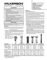
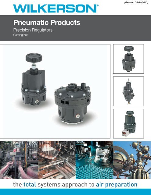
<strong>Pneumatic</strong> <strong>Products</strong><br />
Precision Regulators<br />
<strong>Catalog</strong> <strong>604</strong><br />
the total systems approach to air preparation
<strong>Catalog</strong> <strong>604</strong><br />
Warning, Offer of Sale<br />
Precision Regulators<br />
CAUTION:<br />
REGULATOR PRESSURE ADJUSTMENT – The working range of knob adjustment is designed to permit outlet pressures<br />
within their full range. Pressure adjustment beyond this range is also possible because the knob is not a limiting device. This<br />
is a common characteristic of most industrial regulators, and limiting devices may be obtained only by special design.<br />
For best performance, regulated pressure should always be set by increasing the pressure up to the desired setting.<br />
! WARNING<br />
FAILURE OR IMPROPER SELECTION OR IMPROPER USE OF THE PRODUCTS AND/OR SYSTEMS DESCRIBED HEREIN<br />
OR RELATED ITEMS CAN CAUSE DEATH, PERSONAL INJURY AND PROPERTY DAMAGE.<br />
This document and other information from The Company, its subsidiaries and authorized distributors provide product and/or<br />
system options for further investigation by users having technical expertise. It is important that you analyze all aspects of your<br />
application including consequences of any failure, and review the information concerning the product or system in the current<br />
product catalog. Due to the variety of operating conditions and applications for these products or systems, the user, through<br />
its own analysis and testing, is solely responsible for making the final selection of the products and systems and assuring that<br />
all performance, safety and warning requirements of the application are met.<br />
The products described herein, including without limitation, product features, specifications, designs, availability and pricing,<br />
are subject to change by The Company and its subsidiaries at any time without notice.<br />
Offer of Sale<br />
The items described in this document are hereby offered for sale by The Company, its subsidiaries or its authorized<br />
distributors. This offer and its acceptance are governed by the provisions stated on the separate page of this document entitled<br />
“Offer of Sale”.<br />
© Copyright 2009 Parker Hannifin <strong>Corporation</strong>. All Rights Reserved.<br />
<strong>Pneumatic</strong> Division<br />
Richland, Michigan<br />
www.wilkersoncorp.com
<strong>Catalog</strong> <strong>604</strong><br />
Table of Contents<br />
Precision Regulators<br />
Application Guide..................................................................................................................... 2-3<br />
WRA302 Compact High Precision Regulator.......................................................................... 4-5<br />
WRA102 Standard High Precision Regulator.......................................................................... 6-7<br />
WRA102BP High Precision Relief Valve.................................................................................. 8-9<br />
WRA171 High Precision Vacuum Regulator........................................................................ 10-11<br />
WEA632 Precision Filter / Regulator................................................................................... 12-13<br />
WBA208 Precision <strong>Pneumatic</strong> Input Signal Amplifier.......................................................... 14-15<br />
WBA45 Precision <strong>Pneumatic</strong> Input Signal Amplifier............................................................ 16-17<br />
MPS32 Sensor..................................................................................................................... 18-24<br />
Safety Guide........................................................................................................................ 26-27<br />
Offer of Sale...............................................................................................................................28<br />
1<br />
<strong>Pneumatic</strong> Division<br />
Richland, Michigan<br />
www.wilkersoncorp.com
<strong>Catalog</strong> <strong>604</strong><br />
Application Guide<br />
Precision Regulators<br />
Precision Regulators Application Guide<br />
<strong>Pneumatic</strong> pressure regulators are designed to provide a constant pressure output from a fluctuating supply<br />
pressure – much the way an electronic voltage regulator works. Pressure regulators provide varying degrees<br />
of accuracy with regard to their reduced pressure output. General Purpose pressure regulators work for most<br />
fluid power applications. However, for more pressure-critical applications precision regulators can provide the<br />
customer with the control they need.<br />
A partial listing of things that can potentially cause<br />
regulator output pressure variation are:<br />
• Temperature changes<br />
}<br />
• Inlet pressure changes<br />
• Variations in flow<br />
• Excess downstream pressure<br />
• Cycling<br />
• Time<br />
• Leakage<br />
Pressure (PSIG)<br />
120<br />
100<br />
40<br />
0<br />
Upper Pressure Limit<br />
Lower Pressure Limit<br />
Regulated Pressure for Application<br />
Time<br />
Plant Air Supply<br />
Pressure Range<br />
Supply<br />
Pressure<br />
Variation<br />
Who needs precision regulators?<br />
Design level applications:<br />
When designing a pneumatic system it is important to determine not only the air flow that the application<br />
will require but also the acceptable level of pressure variation. Some pneumatic applications cannot tolerate<br />
fluctuations in pressure. These applications can include static situations with only a steady pressure<br />
maintained, or dynamic flow situations involving any number of changing variables in play while trying to<br />
maintain a constant pressure.<br />
Problem solving device for existing applications:<br />
Sometimes an existing pneumatic application does not meet the customer’s needs with regards to pressure<br />
control and/or stability. Any or all of the variables listed above can cause issues with pressure stability.<br />
As applications are expanded, added on to, or modified the pressure and flow requirements can change.<br />
How do precision regulators differ from general purpose pneumatic regulators?<br />
High Precision Regulators Precision Regulators General Purpose Regulators<br />
Examples- WRA302, P12, P15 / P16, R18, R28, R39, R30<br />
WRA102, WRA102BP,<br />
Dial Air<br />
WRA171<br />
Sensitivity:<br />
.005 to .010 PSIG<br />
Reduced pressure repeatability/variation (1/8” to 1/4” of .5 to 1 PSIG 2 to 4 PSIG<br />
under no-flow condition<br />
water column)<br />
Regulator’s ability to control Begins to relieve at Begins to relieve at Begins to relieve at<br />
back pressure accurately: .005 to .010 PSIG .5 to 2 PSIG 5 to 10 PSIG<br />
*key for cylinder applications overpressure overpressure overpressure<br />
Regulator’s ability to maintain set<br />
pressure under varying flow, High Medium Standard<br />
input pressure, temperature conditions:<br />
Constant Bleed - does the regulator<br />
constantly bleed a small volume of air Yes No No<br />
to the atmosphere to maintain stability?<br />
1" Water Column = .0360 PSI<br />
1PSI = 27.7612 Inches Water Column<br />
2<br />
<strong>Pneumatic</strong> Division<br />
Richland, Michigan<br />
www.wilkersoncorp.com
<strong>Catalog</strong> <strong>604</strong><br />
Application Chart<br />
Precision Regulators<br />
Application Chart<br />
Original Equipment Manufacturers (OEMs)<br />
Air Gauging<br />
Manufacturers of Air Gauging Equipment.<br />
Anesthesia Equipment<br />
Manufacturers<br />
Calibration Stands<br />
Similar to Test Stands<br />
Clamping Pressure Control<br />
End Effect Grippers, Roll Loading<br />
Control Panels<br />
Manufacturers and Users<br />
Coordinate Measuring Machines<br />
Manufacturers use in Force Counterbalance Applications in Z-axis<br />
Dispensing Equipment<br />
Adhesive, Paint, or any other form of Liquid or Gas<br />
Food Process Machinery<br />
Manufacturers<br />
Gas Analyzers<br />
Used for Reference and Calibration Air Pressures<br />
Ink or Paint Robotics Spraying Systems Manufacturers use to Maintain an Even Pressure on System<br />
Leak Testing Equipment<br />
Manufacturers of Equipment that Detects Leaks (i.e., Plastic Bottles)<br />
Medical Equipment<br />
Manufacturers that Utilize for Blood Processing and Sampling as Examples<br />
Oxygen Ventilators<br />
Manufacturers<br />
Pharmaceutical Process Machinery<br />
Pill or Tablet Making Machines<br />
Phone Cable Pressurization Systems<br />
Manufacturers<br />
Polishing Machinery<br />
Used to Maintain Even Pressure on Polishing Head<br />
Semi-conductor Manufacturing Machinery Manufacturers<br />
Smoke Stack Analyzers<br />
Used for Reference and Calibration Air Pressures<br />
Soil or Environmental Analysis Equipment Used for Reference and Calibration Air Pressures<br />
Tank Blanketing<br />
Maintain Pressure on Top Level of a Tank or Storage Vessel<br />
Test Equipment<br />
Similar to Test Stands<br />
Test Stands<br />
Manufacturers of Test Stands, Laboratory Test Stands,<br />
Engineering Test Stands, Production Test Stands<br />
Tool Balancers<br />
Manufacturers of Tool Balancers, Manipulators, and Articulating Arms use High<br />
Relief Capacity Precision Regulators in a Force-balancing Application. Used as<br />
part of a <strong>Pneumatic</strong> Counter-balance System, the Regulator helps suspend the<br />
tool in the air and then makes it easy to move out of the way when not in use.<br />
Web Tensioning<br />
Machinery Builders for Printing Presses, Paper Converting, Packaging,<br />
Textiles, Plastics. Primarily Unwind Stands and Rewind Stands.<br />
System Integrators<br />
Automation Integrators<br />
Energy Controls Systems<br />
HVAC<br />
Anyone Involved in Designs or Projects that Automate Processes<br />
Anyone who would be involved in Designs that would include<br />
Damper and Louvre Control for HVAC Applications<br />
End Users<br />
Instrumentation Supervisors<br />
Instrumentation Technicians<br />
Project Engineers<br />
Store Room Supervisors<br />
MRO<br />
Chemical<br />
Petrochemical<br />
Pulp & Paper<br />
Food & Drug<br />
Refineries<br />
Power<br />
Mining<br />
Oil & Gas<br />
3<br />
<strong>Pneumatic</strong> Division<br />
Richland, Michigan<br />
www.wilkersoncorp.com
<strong>Catalog</strong> <strong>604</strong><br />
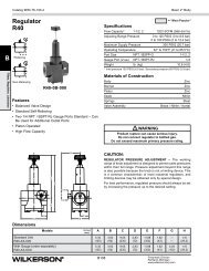
WRA302 Series<br />
Precision Regulators<br />
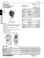
1/4" – Basic 1/4" Body<br />
WRA302 Compact High Precision Regulator<br />
Features<br />
• Control sensitivity of .250"<br />
(.63 cm) water column variation<br />
allows use in precision<br />
applications.<br />
• A compensating diaphragm lets<br />
the regulator remain unaffected<br />
by supply pressure changes.<br />
• Flow of up to 40 SCFM with<br />
100 PSIG supply allows use<br />
in applications with high flow<br />
requirements.<br />
• An aspirator tube compensates<br />
downstream pressure droop<br />
under flow conditions.<br />
• A separate Control Chamber<br />
isolates the diaphragm from the<br />
main flow to eliminate hunting<br />
and buzzing.<br />
• Unit construction lets you service<br />
the Regulator without removing it<br />
from the line.<br />
The WRA302 Regulator is designed for applications that<br />
require high capacity and accurate process control in a small<br />
package. A poppet valve which is balanced by utilizing a<br />
convoluted diaphragm, insures a constant output pressure<br />
even during wide supply pressure variations. Stability<br />
of regulated pressure is maintained under varying flow<br />
conditions through the use of an aspirator tube which adjusts<br />
the air supply in accordance with the flow velocity.<br />
10-32 UNF-2<br />
(2) Mounting<br />
Holes<br />
1/8" NPT<br />
Gauge Ports<br />
(2)<br />
B<br />
A<br />
D<br />
C<br />
E<br />
Standard<br />
Plunger<br />
Operated<br />
0.312 Dia.<br />
! WARNING<br />
A1<br />
Tamperproof<br />
Vent<br />
(Keep<br />
Clear)<br />
WRA302 Regulator<br />
Dimensions<br />
A<br />
2.25<br />
(57.3)<br />
C<br />
3.81<br />
(96.7)<br />
E1<br />
5.56<br />
(141.1)<br />
Inches (mm)<br />
A1<br />
1.70<br />
(43.1)<br />
D<br />
0.25<br />
(6.4)<br />
E1<br />
B<br />
1.25<br />
(31.8)<br />
E<br />
5.22<br />
(132.6)<br />
Product rupture can cause serious injury.<br />
Do not connect regulator to bottled gas.<br />
Do not exceed maximum primary pressure rating.<br />
Ordering Information<br />
WRA302 4 2<br />
Springs<br />
3 0.5 to 30 PSIG<br />
4 1 to 60 PSIG<br />
5 2 to 100 PSIG<br />
Pipe Size<br />
2 1/4" NPT<br />
Options<br />
Blank No Options<br />
H BSPP<br />
N Non-Relieving<br />
Note: Other Spring Ranges, Port Sizes, and Options Available.<br />
Please Consult Factory<br />
BOLD ITEMS ARE MOST POPULAR.<br />
4<br />
<strong>Pneumatic</strong> Division<br />
Richland, Michigan<br />
www.wilkersoncorp.com
<strong>Catalog</strong> <strong>604</strong><br />
Technical Specifications – WRA302<br />
WRA302 Series<br />
Compact High Precision Regulator<br />
Technical Information<br />
Output Pressure kPa<br />
800<br />
700<br />
600<br />
500<br />
400<br />
300<br />
200<br />
100<br />
0<br />
Output Pressure PSIG<br />
120<br />
110<br />
100<br />
90<br />
80<br />
70<br />
60<br />
50<br />
40<br />
30<br />
20<br />
10<br />
Flow Characteristics<br />
Model WRA302<br />
2~100 PSIG (13.8~690 kPa) Range<br />
Supply Pressure = 100 PSIG (690 kPa)<br />
0<br />
-15 -10 -5 0 5 10 15 20 25 30 35 40 45 50 55 60 65 70<br />
Q, SCFM<br />
-400 -200 0 200 400 600 800 1000 1200 1400 1600 1800<br />
Q, LPM<br />
Diaphragm<br />
Assembly<br />
Positive Bias<br />
Spring<br />
Supply<br />
Valve<br />
Inlet<br />
Port<br />
Outlet<br />
Port<br />
Aspirator<br />
Tube<br />
Inner<br />
Valve<br />
Assembly<br />
Operating Principles<br />
The WRA302 Regulator uses the force balance principal<br />
to control the movement of the valve assembly which in<br />
turn controls the output pressure. When the regulator is<br />
adjusted for a specific set point, the downward force of<br />
the Positive Bias Spring causes the Diaphragm Assembly<br />
to move downward. The Supply Valve opens and allows<br />
air to pass to the Outlet Port. As the set point is reached,<br />
the downward force exerted by the Positive Bias spring is<br />
balanced by the upward force of the downstream pressure<br />
acting on the bottom of the Diaphragm Assembly. The<br />
resultant force moves the supply Valve upward to reduce the<br />
flow of air to the Outlet Port.<br />
Outlet pressure is maintained as a result of balance between<br />
forces acting on the top and bottom of the Diaphragm<br />
Assembly.<br />
WRA302 Kits and Accessories<br />
Service Kits<br />
1/2 to 30, 1 to 60, & 2 to 100 PSIG,<br />
Nitrile, Standard....................................................... PS16116-13<br />
1/2 to 30, 1 to 60, & 2 to 100 PSIG,<br />
Nitrile, Non-relieving................................................. PS16116-14<br />
Tamper Resistant Kit.......................................................... PS12163<br />
Mounting Bracket Kit............................................................ PS417B<br />
2.12<br />
(53)<br />
3.40<br />
(83)<br />
3.62<br />
(91)<br />
2.53<br />
(64)<br />
0.20<br />
(5)<br />
1.24<br />
(31) 0.56<br />
(14)<br />
0.45<br />
(11)<br />
1.88<br />
(47)<br />
0.50<br />
(13)<br />
0.62<br />
(16)<br />
0.22<br />
(6)<br />
0.50<br />
(13)<br />
Typ.<br />
Specifications<br />
Supply Pressure........... 250 PSIG, (17.0 bar), (1700 kPa) Maximum<br />
Flow Capacity –<br />
40 SCFM (68 m 3 /HR) @ 100 PSIG, (7.0 bar), (700 kPa) Supply<br />
and 20 PSIG, (1.5 bar), (150 kPa) Setpoint<br />
Exhaust Capacity –<br />
2.0 SCFM (3.4 m 3 /HR) where Downstream Pressure is 5 PSIG,<br />
(.35 bar), (35 kPa) above 20 PSIG, (1.5 bar), (150 kPa) Setpoint<br />
Supply Pressure Effect –<br />
Less than 0.2 PSIG, (.014 bar), (.14 kPa) for 100 PSIG, (7.0 bar),<br />
(700 kPa) change in Supply Pressure<br />
Sensitivity....................... .250" (.010 PSIG) (.64 cm) Water Column<br />
Ambient Temperature....................-40°F to +200°F, (-40°C to 93°C)<br />
Hazardous Locations –<br />
Acceptable for use in Zones 1 and 2 for Gas Atmosphere:<br />
Groups IIA and IIB and Zones 21 and 22 for Dust Atmospheres<br />
Materials of Construction<br />
Body and Housing ............................................................ Aluminum<br />
Diaphragms............................................................. Nitrile on Dacron<br />
Trim............................................................................................ Brass<br />
5<br />
<strong>Pneumatic</strong> Division<br />
Richland, Michigan<br />
www.wilkersoncorp.com
<strong>Catalog</strong> <strong>604</strong><br />
WRA102 Series<br />
WRA102 Standard High Precision Regulator<br />
Precision Regulators<br />
1/4" – Basic 3/8" Body<br />
Features<br />
• Control sensitivity of .125"<br />
(.32 cm) water column allows<br />
use in precision processes.<br />
• Pressure balanced supply<br />
valve prevents supply pressure<br />
changes from affecting the<br />
setpoint.<br />
• Optional check valve permits<br />
dumping of downstream<br />
pressure when supply is<br />
opened to atmosphere.<br />
• Separate control chamber<br />
isolates the diaphragm from<br />
the main flow to eliminate<br />
hunting and buzzing.<br />
• An aspirator tube<br />
compensates<br />
downstream pressure droop<br />
under flow conditions.<br />
The WRA102 Regulator is designed for applications that<br />
require high capacity and accurate process control. A poppet<br />
valve which is balanced by utilizing a rolling diaphragm,<br />
insures a constant output pressure even during wide supply<br />
pressure variations. Stability of regulated pressure is<br />
maintained under varying flow conditions through the use of<br />
an aspirator tube which adjusts the air supply in accordance<br />
with the flow velocity.<br />
Standard<br />
1/4-20<br />
.5" Deep<br />
(2) Mounting<br />
Holes<br />
1/4" NPT<br />
Gauge Ports<br />
(2)<br />
A<br />
2 thru 200 PSIG Range<br />
D<br />
B<br />
C<br />
E<br />
1/4-20<br />
.5" Deep<br />
(2) Mounting<br />
Holes<br />
1/4" NPT<br />
Gauge Ports<br />
(2)<br />
! WARNING<br />
Plunger<br />
Operated<br />
0.312 Dia.<br />
Tamperproof<br />
A<br />
300 & 400 PSIG Range<br />
D<br />
B1<br />
C1<br />
WRA102 Regulator<br />
Dimensions<br />
A<br />
3.00<br />
(76.2)<br />
C<br />
4.42<br />
(111.9)<br />
E<br />
6.63<br />
(168.5)<br />
Inches (mm)<br />
B<br />
2.22<br />
(56.5)<br />
C1<br />
4.78<br />
(121.6)<br />
E1<br />
7.28<br />
(184.9)<br />
E1<br />
B1<br />
2.13<br />
(53.9)<br />
D<br />
0.38<br />
(9.4)<br />
Product rupture can cause serious injury.<br />
Do not connect regulator to bottled gas.<br />
Do not exceed maximum primary pressure rating.<br />
Ordering Information<br />
WRA102 6 2<br />
Springs<br />
3 0.5 to 30 PSIG<br />
4 1 to 60 PSIG<br />
6 2 to 150 PSIG<br />
Pipe Size<br />
2 1/4" NPT<br />
Options<br />
Blank No Options<br />
H BSPP<br />
N Non-Relieving<br />
Note: Other Spring Ranges, Port Sizes, and Options Available.<br />
Please Consult Factory<br />
BOLD ITEMS ARE MOST POPULAR.<br />
6<br />
<strong>Pneumatic</strong> Division<br />
Richland, Michigan<br />
www.wilkersoncorp.com
<strong>Catalog</strong> <strong>604</strong><br />
Technical Specifications – WRA102<br />
WRA102 Series<br />
Standard High Precision Regulator<br />
Technical Information<br />
Output Pressure kPa<br />
700<br />
600<br />
500<br />
400<br />
300<br />
200<br />
100<br />
0<br />
Output Pressure PSIG<br />
110<br />
100<br />
90<br />
80<br />
70<br />
60<br />
50<br />
40<br />
30<br />
20<br />
10<br />
Flow Characteristics<br />
Model WRA102<br />
90 PSIG Setpoint (620 kPa)<br />
75 PSIG Setpoint (517 kPa)<br />
60 PSIG Setpoint (414 kPa)<br />
45 PSIG Setpoint (310 kPa)<br />
30 PSIG Setpoint (206 kPa)<br />
Supply Pressure = 100 PSIG (690 kPa)<br />
0<br />
-15 -10 -5 0 5 10 15 20 25 30 35 40 45 50 55 60 65 70<br />
Q, SCFM<br />
-400 -200 0 200 400 600 800 1000 1200 1400 1600 1800<br />
Q, LPM<br />
Supply<br />
Valve<br />
Inlet<br />
Port<br />
Inner<br />
Valve<br />
Assembly<br />
Gauge Port (2)<br />
Positive Bias<br />
Spring<br />
Diaphragm<br />
Assembly<br />
Outlet<br />
Port<br />
Operating Principles<br />
The WRA102 Series regulator use the force balance<br />
principal to control the movement of the Valve Assembly that<br />
controls the output pressure. When the regulator is adjusted<br />
for a specific set point, the downward force of the Positive<br />
Bias Spring moves the Diaphragm Assembly downward.<br />
The Supply Valve opens and allows air to pass to the Outlet<br />
Port. As the set point is reached, the downward force<br />
exerted by the Positive Bias Spring is balanced by the force<br />
of the downstream pressure that acts on the Diaphragm<br />
Assembly. The resultant force moves the Supply Valve<br />
upward to reduce the flow of air to the Outlet Port.<br />
Outlet pressure is maintained as a result of balance between<br />
forces acting on the top and bottom of the Diaphragm<br />
Assembly.<br />
WRA102 Kits & Accessories<br />
Mounting Bracket Kit –<br />
Zinc Plated Steel.............................................................. PS09921<br />
1-7/8 to cL<br />
(47.6) of Unit<br />
11/32<br />
(8.7)<br />
Dia. (2)<br />
3/4<br />
(19.1)<br />
7/32 Dia. (3)<br />
(5.5) 3/8<br />
(9.5)<br />
2-1/4<br />
(57.2)<br />
3<br />
(76.2)<br />
9/16<br />
(14.4)<br />
27/32<br />
(21.6)<br />
1-7/16<br />
(36.6)<br />
1-1/8<br />
(28.6)<br />
Service Kits<br />
0 to 200 PSIG, Relieving............................................... PS12125-1<br />
0 to 200 PSIG, Non-‐relieving........................................ PS12125-4<br />
Tamper Resistant Kit.......................................................... PS12165<br />
Specifications<br />
Supply Pressure........... 500 PSIG, (35.0 bar), (3500 kPa) Maximum<br />
Flow Capacity –<br />
40 SCFM (68 m 3 /HR) @ 100 PSIG, (7.0 bar), (700 kPa) Supply<br />
and 20 PSIG, (1.5 bar), (150 kPa) Setpoint<br />
Exhaust Capacity –<br />
5.5 SCFM (9.35 m 3 /HR) where Downstream Pressure is 5 PSIG,<br />
(.35 bar), (35 kPa) above 20 PSIG, (1.5 bar), (150 kPa) Setpoint<br />
Supply Pressure Effect –<br />
Less than 0.1 PSIG, (.007 bar), (.7 kPa) for 100 PSIG, (7.0 bar),<br />
(700 kPa) change in Supply Pressure<br />
Sensitivity....................... .125" (.005 PSIG) (.32 cm) Water Column<br />
Ambient Temperature....................-40°F to +200°F, (-40°C to 93°C)<br />
Hazardous Locations –<br />
Acceptable for use in Zones 1 and 2 for Gas Atmosphere:<br />
Groups IIA and IIB and Zones 21 and 22 for Dust Atmospheres<br />
Materials of Construction<br />
Body and Housing ............................................................ Aluminum<br />
Diaphragms........................ Buna N on Dacron (Standard Unit Only)<br />
Trim...............................................................Brass, Zinc Plated Steel<br />
7<br />
<strong>Pneumatic</strong> Division<br />
Richland, Michigan<br />
www.wilkersoncorp.com
<strong>Catalog</strong> <strong>604</strong><br />
WRA102BP Series<br />
WRA102BP High Precision Relief Valve<br />
Precision Regulators<br />
1/4" – Basic 3/8" Body<br />
Features<br />
• Control sensitivity of .125"<br />
(.32 cm) water column allows<br />
use in precision applications.<br />
• A separate Control Chamber<br />
and Aspirator Tube isolate<br />
the diaphragm from the main<br />
flow to eliminate hunting and<br />
buzzing.<br />
• Unit construction lets you<br />
service the WRA102BP<br />
without removing it from<br />
the line.<br />
• Mounting Bracket is<br />
available.<br />
The WRA102BP is a high capacity relief valve that relieves<br />
excess pressure in a pneumatic system.<br />
The WRA102BP provides greater accuracy than standard<br />
relief valves over a narrow pressure range. The WRA102BP<br />
is an excellent choice for a wide range of precision<br />
applications.<br />
1/4-20<br />
.5" Deep<br />
(2) Mounting<br />
Holes<br />
Standard<br />
1/4" NPT<br />
Gauge Ports<br />
(2)<br />
B<br />
C<br />
E<br />
1/4-20<br />
.5" Deep<br />
(2) Mounting<br />
Holes<br />
1/4" NPT<br />
Gauge Ports<br />
(2)<br />
A<br />
A<br />
2 thru 200 PSIG Range 300 & 400 PSIG Range<br />
! WARNING<br />
Tamperproof<br />
Product rupture can cause serious injury.<br />
Do not connect regulator to bottled gas.<br />
Do not exceed maximum primary pressure rating.<br />
C1<br />
E1<br />
PWRA102BP Regulator<br />
Dimensions<br />
A<br />
3.00<br />
(76.2)<br />
C1<br />
4.56<br />
(115.9)<br />
Inches (mm)<br />
B<br />
0.97<br />
(24.6)<br />
E<br />
6.31<br />
(160.3)<br />
C<br />
4.19<br />
(106.4)<br />
E1<br />
6.75<br />
(171.4)<br />
Ordering Information<br />
WRA102 6 2 BP<br />
Springs<br />
3 0.5 to 30 PSIG<br />
4 1 to 60 PSIG<br />
6 2 to 150 PSIG<br />
Pipe Size<br />
2 1/4" NPT<br />
Options<br />
BP Back Pressure<br />
Options<br />
Blank No Options<br />
H BSPP<br />
N Non-Relieving<br />
Note: Other Spring Ranges, Port Sizes, and Options Available.<br />
Please Consult Factory<br />
BOLD ITEMS ARE MOST POPULAR.<br />
8<br />
<strong>Pneumatic</strong> Division<br />
Richland, Michigan<br />
www.wilkersoncorp.com
<strong>Catalog</strong> <strong>604</strong><br />
Technical Specifications – WRA102BP<br />
WRA102BP Series<br />
High Precision Relief Valve<br />
Technical Information<br />
150<br />
Flow Characteristics<br />
Model WRA102BP<br />
120 PSIG Setpoint (827 kPa)<br />
Output Pressure PSIG<br />
100<br />
50<br />
0<br />
90 PSIG Setpoint (620 kPa)<br />
60 PSIG Setpoint (414 kPa)<br />
30 PSIG Setpoint (207 kPa)<br />
0 20 40 60 80 100<br />
Flow Rate - SCFM<br />
Supply<br />
Valve<br />
To<br />
Atmosphere<br />
Relief<br />
Valve<br />
Gauge Port (2)<br />
Positive Bias<br />
Spring<br />
Diaphragm<br />
Assembly<br />
System<br />
Pressure<br />
Aspirator<br />
Tube<br />
Operating Principles<br />
The WRA102BP Regulator uses the force balance principle<br />
to open the Relief Valve and vent system pressure when the<br />
set point is exceeded.<br />
Downstream pressure is transmitted through the Aspirator<br />
Tube to the bottom of the Diaphragm Assembly. When you<br />
adjust the range screw for a specific set point, the Positive<br />
Bias Spring compresses and exerts a force on the top of<br />
the Diaphragm Assembly. As long as the pressure acting<br />
on the bottom of the Diaphragm Assembly produces a force<br />
less than the spring force acting on the top of the Diaphragm<br />
Assembly, the Relief Valve remains closed. When<br />
system pressure increases, the force on the bottom of the<br />
Diaphragm Assembly increases until it reaches the set point.<br />
When system pressure increases beyond the set point, the<br />
assembly moves upward, lifting the Relief Valve from its seat<br />
and vents the downstream air.<br />
If downstream pressure decreases below the set point, the<br />
assembly moves downward closing the Relief Valve.<br />
WRA102BP Kits & Accessories<br />
Mounting Bracket Kit –<br />
Zinc Plated Steel.............................................................. PS09921<br />
1-7/8 to cL<br />
(47.6) of Unit<br />
11/32<br />
(8.7)<br />
Dia. (2)<br />
3/4<br />
(19.1)<br />
7/32 Dia. (3)<br />
(5.5) 3/8<br />
(9.5)<br />
2-1/4<br />
(57.2)<br />
3<br />
(76.2)<br />
9/16<br />
(14.4)<br />
27/32<br />
(21.6)<br />
1-7/16<br />
(36.6)<br />
1-1/8<br />
(28.6)<br />
Service Kits<br />
0 to 200 PSIG, Standard............................................... PS12127-1<br />
Tamper Resistant Kit.......................................................... PS12165<br />
Specifications<br />
Set Point Range System Pressure (Maximum)<br />
2-200 PSIG 300 PSIG<br />
(0.15-14 bar) (21.0 bar)<br />
(15-1400 kPa) (2100 kPa)<br />
300-400 PSIG 500 PSIG<br />
(21-28 bar) (35.0 bar)<br />
(2100-2800 kPa) (3500 kPa)<br />
Flow Capacity (SCFM) –<br />
40 (68 m 3 /HR) @ 100 PSIG, (7.0 bar), (700 kPa) System<br />
Pressure<br />
Sensitivity...................... .125" (.005 PSIG) (.32 cm) Water Column<br />
Ambient Temperature................. -40°F to +200°F, (-40°C to +93°C)<br />
Materials of Construction<br />
Body and Housing............................................................. Aluminum<br />
Trim...............................................................Zinc Plated Steel, Brass<br />
Nozzle....................................................................... Nitrile on Dacron<br />
9<br />
<strong>Pneumatic</strong> Division<br />
Richland, Michigan<br />
www.wilkersoncorp.com
<strong>Catalog</strong> <strong>604</strong><br />
WRA171 Series<br />
Vacuum Regulators<br />
1/4", 3/8" & 1/2" – Basic 3/8" Body<br />
WRA171 High Precision Vacuum Regulator<br />
Features<br />
• Control sensitivity of .125"<br />
(.32 cm) water column allows use in<br />
precision applications.<br />
• Balanced supply valve minimizes<br />
effects of vacuum variation.<br />
• Aspirator tube compensates for<br />
downstream pressure droop under<br />
flow conditions.<br />
• Separate control chamber isolates<br />
the diaphragm from the main flow<br />
to eliminate hunting and buzzing.<br />
• Construction allows servicing<br />
without removing from the line.<br />
The WRA171 is a high accuracy vacuum regulator that<br />
provides uniform vacuum regulation independent of vacuum<br />
supply changes and flow demand.<br />
This unit has a diaphragm assembly with three springs to<br />
provide a more balanced loading of the diaphragm.<br />
1/4-20<br />
.5" Deep<br />
(2) Mounting<br />
Holes<br />
1/4" NPT<br />
Gauge Ports<br />
(2)<br />
! WARNING<br />
Product rupture can cause serious injury.<br />
Do not connect regulator to bottled gas.<br />
Do not exceed maximum primary pressure rating.<br />
A<br />
D<br />
B<br />
C<br />
WRA171 Regulator<br />
Dimensions<br />
A<br />
3.00<br />
(76.2)<br />
D<br />
1.00<br />
(25.4)<br />
Inches (mm)<br />
B<br />
1.13<br />
(28.7)<br />
E<br />
5.96<br />
(151.3)<br />
E<br />
C<br />
4.83<br />
(122.6)<br />
Ordering Information<br />
WRA171 3 2 N N K N<br />
Springs<br />
3 0 to 30 Hg<br />
Pipe Size<br />
2 1/4" NPT<br />
Thread Type<br />
N NPT<br />
Options<br />
N Nitrile<br />
Options<br />
K Knob Assembly<br />
Options<br />
N Non-Relieving<br />
Note: Other Spring Ranges, Port Sizes, and Options Available.<br />
Please Consult Factory<br />
BOLD ITEMS ARE MOST POPULAR.<br />
10<br />
<strong>Pneumatic</strong> Division<br />
Richland, Michigan<br />
www.wilkersoncorp.com
<strong>Catalog</strong> <strong>604</strong><br />
WRA171 Series<br />
WRA171 Series<br />
High Precision Vacuum Regulator<br />
Technical Information<br />
0<br />
0<br />
Flow Characteristics<br />
Model WRA171<br />
Adjusting<br />
Knob<br />
Output Pressure kPa<br />
-20 -3<br />
-40<br />
-60<br />
-80<br />
-100<br />
Output Pressure PSIG<br />
-6<br />
-9<br />
-12<br />
-15<br />
0<br />
0.1 0.2 0.3 0.4 0.5 0.6<br />
Q, SCFM<br />
0 2 4 6 8 10 12 14 16<br />
Q, LPM<br />
Diaphragm<br />
Assembly<br />
Control<br />
Chamber<br />
Supply<br />
Valve<br />
Vacuum<br />
Supply<br />
Range<br />
Springs<br />
Outlet<br />
Chamber<br />
Operating Principles<br />
The Model WRA171 Series vacuum regulator uses the<br />
force balance principle to control the movement of the Valve<br />
Assembly that controls output vacuum.<br />
When the regulator is adjusted for a specific set point, the<br />
upward force of the Range Springs moves the Diaphragm<br />
Assembly upward. The Supply Valve opens and allows air to<br />
pass to the inlet port. As the set point is reached, the upward<br />
force exerted by the Range Springs is balanced by the<br />
force of the vacuum that pulls downward on the Diaphragm<br />
Assembly. The resultant force moves the Supply Valve<br />
downward to reduce the flow of air to the inlet port. Outlet<br />
vacuum is maintained as a result of balance between forces<br />
acting on the top and bottom of the Diaphragm Assembly.<br />
WRA171 Kits and Accessories<br />
Mounting Bracket................................................................ PS09921<br />
1-7/8 to cL<br />
(47.6) of Unit<br />
11/32<br />
(8.7)<br />
Dia. (2)<br />
3/4<br />
(19.1)<br />
7/32 Dia. (3)<br />
(5.5) 3/8<br />
(9.5)<br />
2-1/4<br />
(57.2)<br />
3<br />
(76.2)<br />
9/16<br />
(14.4)<br />
27/32<br />
(21.6)<br />
1-7/16<br />
(36.6)<br />
1-1/8<br />
(28.6)<br />
Specifications<br />
Vacuum Supply (Max)..........................................29.92 Hg (760 torr)<br />
Flow Capacity.............3 SCFM @ 650 torr Sypply, 250 torr Setpoint<br />
Sensitivity....................... .125" (.005 PSIG) (.32 cm) Water Column<br />
Ambient Temperature................. -40°F to +200°F, (-40°C to +93°C)<br />
Vacuum Supply Effect –<br />
Less than 1 torr for 100 torr (.04 Hg for 3.94 Hg) Change in<br />
Vacuum Supply<br />
Materials of Construction<br />
Body and Housing............................................................. Aluminum<br />
Trim...............................................................Zinc Plated Steel, Brass<br />
Elastomers................................................................................. Nitrile<br />
Service Kits<br />
(Includes Diaphragm Assy, Valve Assy, Seat Assy & Gasket) –<br />
0-30" Hg, Nitrile, Nonrelieving........................................ PS20966-9<br />
Tamper Resistant Kit....................................................... PS20967-1<br />
11<br />
<strong>Pneumatic</strong> Division<br />
Richland, Michigan<br />
www.wilkersoncorp.com
➤<br />
<strong>Catalog</strong> <strong>604</strong><br />
WEA632 Series<br />
Filter / Regulators<br />
1/4" – Basic 1/4" Body<br />
WEA632 Precision Filter / Regulator<br />
➤<br />
➤<br />
➤<br />
Features<br />
• The no-brass construction is well suited to<br />
harsh environments.<br />
➤<br />
➤<br />
➤<br />
• Internal and external epoxy finish for<br />
superior corrosion resistance.<br />
• Non-bleed design to reduce consumption.<br />
• Integral Relief Valve.<br />
C<br />
E<br />
F<br />
• A Gauge Port provides convenient<br />
pressure gauge mounting.<br />
• The standard 5-micron filter minimizes<br />
internal contamination.<br />
D<br />
• The Filter Dripwell contains a Drain Plug<br />
to easily drain trapped liquids.<br />
B<br />
A<br />
• Standard Tapped Exhaust.<br />
• Soft Relief Seat minimizes air loss.<br />
WEA632 Regulator<br />
Dimensions<br />
A<br />
2.83<br />
(71.9)<br />
B<br />
2.25<br />
(57.2)<br />
C<br />
7.88<br />
(200)<br />
D<br />
2.96<br />
(75)<br />
E<br />
7.52<br />
(1916)<br />
F<br />
8.19<br />
(209)<br />
Inches (mm)<br />
! WARNING<br />
Product rupture can cause serious injury.<br />
Do not connect regulator to bottled gas.<br />
Do not exceed maximum primary pressure rating.<br />
Ordering Information<br />
WEA632 5 2 N S<br />
Springs<br />
4 1 to 60 PSIG<br />
5 2 to 120 PSIG<br />
Pipe Size<br />
2 1/4" NPT<br />
Thread Type<br />
N NPT<br />
U BSPP<br />
Adjustment<br />
S Screw (Std.)<br />
K Knob<br />
T Tamperproof<br />
Options<br />
Blank None<br />
Note: Other Spring Ranges, Port Sizes, and Options Available.<br />
Please Consult Factory<br />
BOLD ITEMS ARE MOST POPULAR.<br />
12<br />
<strong>Pneumatic</strong> Division<br />
Richland, Michigan<br />
www.wilkersoncorp.com
<strong>Catalog</strong> <strong>604</strong><br />
WEA632 Series<br />
WEA632 Series<br />
Precision Filter / Regulator<br />
Technical Information<br />
140<br />
Flow Characteristics<br />
Model WEA632<br />
Supply Pressure = 150 PSIG<br />
Bonnet<br />
120<br />
Diaphragm<br />
Assembly<br />
Output Pressure PSIG<br />
100<br />
80<br />
60<br />
40<br />
90 PSIG Setpoint (620 kPa)<br />
75 PSIG Setpoint (517 kPa)<br />
60 PSIG Setpoint (414 kPa)<br />
45 PSIG Setpoint (310 kPa)<br />
Body<br />
20<br />
30 PSIG Setpoint (206 kPa)<br />
Dripwell<br />
Assembly<br />
0<br />
-5 0 5 10 15 20 25 30 35 40 45<br />
Air Flow - SCFM<br />
Drain<br />
Cock<br />
Operating Principles<br />
When you turn the Adjustment Screw to a specific setpoint,<br />
the Spring exerts a downward force against the top of<br />
the Diaphragm Assembly. This downward force opens the<br />
Supply Valve. Output pressure flows through the Outlet Port<br />
and the passage to the Control Chamber where it creates an<br />
upward force on the bottom of the Diaphragm Assembly.<br />
When the setpoint is reached, the force of the Spring that<br />
acts on the top of the Diaphragm Assembly balances with<br />
the force of output pressure that acts on the bottom of the<br />
Diaphragm Assembly and closes the Supply Valve.<br />
When the output pressure increases above the setpoint, the<br />
Diaphragm Assembly moves upward to close the Supply<br />
Valve and open the Exhaust Valve. Output pressure flows<br />
through the Exhaust Valve and out of the Exhaust Vent on<br />
the side of the unit until it reaches the setpoint.<br />
WEA632 Kits & Accessories<br />
Service Kits<br />
1 to 60, 2 to 120 PSIG................................................ PS19968-NR<br />
Tamper Resistant Kit.......................................................... PS12165<br />
Specifications<br />
Supply Pressure................. 250 PSIG, (17 bar), (1700 kPa) Maximum<br />
Flow Capacity (SCFM)..............25 (42.5 m 3 /HR) @ 100 psig, (7 bar),<br />
(700 kPa) supply and 20 PSIG, (1.5 bar), (150 kPa) setpoint<br />
Exhaust Capacity (SCFM).......................................0.8 (1.36 m 3 /HR)<br />
where d ownstream pressure is 5 PSIG, (.35 bar), (35 kPa)<br />
above 20 PSIG, (1.5 bar), (150 kPa) setpoint.<br />
(0.8 SCFM for 120 # unit)<br />
13<br />
Maximum Supply Pressure............. 250 PSIG, (14 bar), (1400 kPa)<br />
Consumption..................................................................Undetectable<br />
Supply Pressure Effect.................... Less than 1.25 PSIG, (.09 bar),<br />
(9 kPa) change for 100 psig, (7.0 bar), (700 kPa)<br />
change in supply pressure (1.90 psig for 120 # unit)<br />
Sensitivity.........................1.0" (.036 PSIG) (2.54 cm) Water Column<br />
Temperature Range.................... -40 o F to + 160 o F, (-40 o C to + 71 o C)<br />
Materials of Construction<br />
Body and Housing......................................Epoxy Coated Aluminum<br />
Trim............................................. Stainless Steel, Nickel Plated Steel<br />
Elastomers..................................................................................Nitrile<br />
<strong>Pneumatic</strong> Division<br />
Richland, Michigan<br />
www.wilkersoncorp.com
<strong>Catalog</strong> <strong>604</strong><br />
WBA208 Series<br />
Precision <strong>Pneumatic</strong> Input Signal Amplifier<br />
1/4" – Basic 1/4" Body<br />
WBA208 Precision <strong>Pneumatic</strong> Input Signal Amplifier<br />
Features<br />
• The WBA208 uses a pneumatic<br />
input signal to accurately<br />
control output pressure based<br />
on a predetermined ratio.<br />
• A balanced Supply Valve<br />
minimizes the effects of supply<br />
pressure variation.<br />
• An Aspirator Tube<br />
compensates downstream<br />
pressure droop under flowing<br />
conditions.<br />
• Optional Adjustable By-Pass<br />
Needle Valve allows tuning for<br />
optimum dynamic response<br />
(1:1 ratio only).<br />
• Optional Fixed Negative<br />
Bias allows operation with<br />
pneumatic devices that cannot<br />
be adjusted to zero input<br />
pressure.<br />
• A separate Control Chamber<br />
isolates the diaphragm from the<br />
main flow to eliminate hunting<br />
and buzzing.<br />
• Unit construction allows<br />
servicing without removal.<br />
• Mounting Bracket available.<br />
1:1, 1:2, 1:3,<br />
2:1 & 3:1<br />
Ratios<br />
1/4" NPT<br />
Tapped Exhaust<br />
1:1, 1:2, 1:3,<br />
2:1 & 3:1<br />
Ratios Only<br />
B<br />
E<br />
for Ratios<br />
1:1, 1:2, 1:3,<br />
2:1 & 3:1<br />
1/4" NPT<br />
Inlet Port<br />
(Typical)<br />
C1<br />
1/4" NPT<br />
Gage Port<br />
(Typical)<br />
1/4" NPT<br />
Signal Port<br />
D<br />
A<br />
By-Pass Valve<br />
1:1 Ratio Only<br />
1:4, 1:5, 1:6,<br />
4:1 & 5:1<br />
Ratios<br />
E1<br />
for Ratios<br />
1:4, 1:5, 1:6,<br />
4:1 & 5:1<br />
C1<br />
C<br />
1/4" NPT<br />
Outlet Port<br />
(Typical)<br />
WBA208 Regulator<br />
Dimensions<br />
A<br />
3.00<br />
(76.2)<br />
C1<br />
.94<br />
(23.8)<br />
E1<br />
4.31<br />
(109.5)<br />
Inches (mm)<br />
B<br />
.94<br />
(23.8)<br />
D<br />
.13<br />
(3.2)<br />
C<br />
2.13<br />
(53.9)<br />
E<br />
3.88<br />
(98.3)<br />
Ordering Information<br />
WBA208 1 2<br />
Pilot Ratio<br />
1 1:1<br />
2 1:2<br />
3 1:3<br />
Pipe Size<br />
2 1/4" NPT<br />
Options<br />
Blank No Options<br />
E Tapped Exhaust<br />
H BSPP<br />
I By-Pass Valve<br />
Note: Other Spring Ranges, Port Sizes, and Options Available.<br />
Please Consult Factory<br />
BOLD ITEMS ARE MOST POPULAR.<br />
14<br />
<strong>Pneumatic</strong> Division<br />
Richland, Michigan<br />
www.wilkersoncorp.com
<strong>Catalog</strong> <strong>604</strong><br />
WBA208 Series<br />
WBA208 Series<br />
Precision <strong>Pneumatic</strong> Input Signal Amplifier<br />
Technical Information<br />
Output Pressure PSIG<br />
20<br />
15<br />
10<br />
5<br />
Flow Characteristics<br />
Model WBA208<br />
3 PSIG Setpoint (21 kPa)<br />
Supply Pressure = 80 PSIG<br />
15 PSIG Setpoint (103 kPa)<br />
9 PSIG Setpoint (62 kPa)<br />
Inlet<br />
Port<br />
Outlet<br />
Port<br />
By-Pass<br />
Valve<br />
Upper<br />
Diaphragm<br />
Lower<br />
Diaphragm<br />
Exhaust<br />
Valve<br />
Seat Assembly<br />
Supply<br />
Valve<br />
Inner<br />
Valve<br />
Assembly<br />
0<br />
-5 0 5 10 15 20 25 30 35 40 45 50<br />
Air Flow - SCFM<br />
Materials of Construction<br />
Body and Housing ............................................................ Aluminum<br />
Diaphragm.................................................... Nitrile on Dacron Fabric<br />
Trim...............................................................Zinc Plated Steel, Brass<br />
Operating Principles<br />
The WBA208 Input Signal Amplifier is a pneumatic device capable<br />
of high flow and exhaust capacity. This device uses a force balance<br />
system to control the movement of the supply and exhaust valves.<br />
At set point, the force due to signal pressure that acts on the top of<br />
the Upper Diaphragm balances with the force due to output pressure<br />
acting on the bottom of the Lower Diaphragm.<br />
Specifications<br />
Maximum Output Pressure, PSIG (bar)<br />
Maximum Supply Pressure, PSIG (bar)<br />
Signal:Output<br />
Ratio 1:1 1:2 1:3<br />
Flow Capacity SCFM, (m 3 /HR)<br />
100 PSIG, (7.0 bar ) Supply, 20 PSIG, (1.5 bar ) Output.<br />
Exhaust Capacity SCFM, (m 3 /HR)<br />
Downstream Pressure 5 PSIG, (.35 bar) Above Output<br />
Pressure Set Point of 20 PSIG, (1.5 bar).<br />
Sensitivity (Water Column)<br />
150<br />
(10.0)<br />
250<br />
(17.0)<br />
45<br />
(76.5)<br />
11<br />
(18.7)<br />
.250"<br />
(.64 cm)<br />
150<br />
(10.0)<br />
250<br />
(17.0)<br />
45<br />
(76.5)<br />
11<br />
(18.7)<br />
.500"<br />
(1.27 cm)<br />
150<br />
(10.0)<br />
250<br />
(17.0)<br />
45<br />
(76.5)<br />
11<br />
(18.7)<br />
.750"<br />
(1.9 cm)<br />
Ratio Accuracy<br />
% of 100 PSIG, (7.0 bar) Output Span<br />
1.0 1.0 1.0<br />
% of Output Span with (7.0 bar) Input Span — — —<br />
Supply Pressure Effect, PSIG (bar)<br />
for change of 100 PSIG, (7.0 bar).<br />
Ambient Temperature, °F (°C)<br />
0.10<br />
(.007)<br />
0.20<br />
(.014)<br />
-40 to +200<br />
(-40 to +93)<br />
0.30<br />
(.021)<br />
WBA208 Kits and Accessories<br />
Mounting Bracket................................................................ PS09921<br />
Service Kits<br />
1:1 Ratio....................................................................... PS19513-11<br />
1:1 Ratio w/ By-Pass Valve.........................................PS19513-11I<br />
1:2 Ratio....................................................................... PS19513-12<br />
1:3 Ratio....................................................................... PS19513-13<br />
15<br />
1-7/8 to cL<br />
(47.6) of Unit<br />
11/32<br />
(8.7)<br />
Dia. (2)<br />
3/4<br />
(19.1)<br />
7/32 Dia. (3)<br />
(5.5) 3/8<br />
(9.5)<br />
2-1/4<br />
(57.2)<br />
3<br />
(76.2)<br />
9/16<br />
(14.4)<br />
27/32<br />
(21.6)<br />
1-7/16<br />
(36.6)<br />
1-1/8<br />
(28.6)<br />
<strong>Pneumatic</strong> Division<br />
Richland, Michigan<br />
www.wilkersoncorp.com
<strong>Catalog</strong> <strong>604</strong><br />
WBA45 Series<br />
WBA45 Precision <strong>Pneumatic</strong> Input Signal Amplifier<br />
Precision <strong>Pneumatic</strong> Input Signal Amplifier<br />
1/2" & 3/4" – Basic 1/2" Body<br />
Features<br />
• Five signal to output ratios meet most<br />
control element requirements.<br />
• Control sensitivity of water column<br />
allows use in precision applications.<br />
• Large Supply and Exhaust Valves<br />
provide high forward and exhaust<br />
flows.<br />
• Soft Supply and Exhaust Valve seats<br />
minimize air consumption.<br />
• A balanced Supply Valve minimizes<br />
the effect of supply pressure variation.<br />
• An Aspirator Tube compensates<br />
downstream pressure droop under<br />
flow conditions. <br />
• A separate Control Chamber isolates<br />
the diaphragm from the main flow to<br />
eliminate hunting and buzzing.<br />
• Optional remote feedback port<br />
minimizes pressure drop at final<br />
control element under flow conditions.<br />
• The optional adjustable By-pass Valve<br />
lets you tune for optimum dynamic<br />
response. (1:1 ratio only)<br />
• Unit construction lets you service the<br />
WBA45 without removing it from<br />
the line.<br />
E1<br />
1/2" NPT<br />
Exhaust<br />
Port<br />
(Optional)<br />
C<br />
C1<br />
3/8" NPT<br />
Inlet Port<br />
(Typical)<br />
1/4" NPT<br />
Signal<br />
Port<br />
D<br />
A<br />
1" Hex<br />
1/4" NPT<br />
Gage Port<br />
(Typical)<br />
B<br />
WBA45 Regulator<br />
Dimensions<br />
A<br />
4.50<br />
(114.3)<br />
C1<br />
1.56<br />
(39.6)<br />
E1<br />
5.83<br />
(148.2)<br />
Inches (mm)<br />
B<br />
3.41<br />
(86.5)<br />
D<br />
.31<br />
(7.9)<br />
By-Pass Valve<br />
1:1 Ratio Only<br />
Exhaust<br />
Vents (8)<br />
(Keep<br />
Clear)<br />
1/8" NPT<br />
Remote<br />
Feedback<br />
Port<br />
(Optional)<br />
C1<br />
E<br />
3/8" NPT<br />
Outlet Port<br />
(Typical)<br />
C<br />
3.86<br />
(98)<br />
E<br />
5.07<br />
(128.8)<br />
Ordering Information<br />
WBA45 1 4 A<br />
Pilot Ratio<br />
1 1:1<br />
2 1:2<br />
3 1:3<br />
Pipe Size<br />
4 1/2" NPT<br />
6 3/4" NPT<br />
Type<br />
A 45 Series<br />
Options<br />
Blank No Options<br />
E Tapped Exhaust<br />
H BSPP<br />
I By-Pass Valve<br />
Note: Other Spring Ranges, Port Sizes, and Options Available.<br />
Please Consult Factory<br />
BOLD ITEMS ARE MOST POPULAR.<br />
16<br />
<strong>Pneumatic</strong> Division<br />
Richland, Michigan<br />
www.wilkersoncorp.com
<strong>Catalog</strong> <strong>604</strong><br />
WBA45 Series<br />
WBA45 Series<br />
Precision <strong>Pneumatic</strong> Input Signal Amplifier<br />
Technical Information<br />
Output Pressure PSIG<br />
120<br />
100<br />
80<br />
60<br />
40<br />
20<br />
Materials of Construction<br />
Body and Housing ............................................................ Aluminum<br />
Diaphragm........................................................Nitrile on Dacron Fabric<br />
Trim..................................................................Zinc Plated Steel, Brass<br />
Specifications<br />
Maximum Output Pressure, PSIG (bar)<br />
Maximum Supply Pressure, PSIG (bar)<br />
Operating Principles<br />
When signal pressure on the top of the Signal Diaphragm creates<br />
a downward force on the Diaphragm Assembly, the Supply Valve<br />
opens. Output pressure flows through the Outlet Port and the<br />
Aspirator Tube to the Control Chamber to create an upward force on<br />
the bottom of the Control Diaphragm. When the setpoint is reached,<br />
the force of the signal pressure that acts on the top of the Signal<br />
Diaphragm balances with the force of the output pressure that acts<br />
on the bottom of the Control Diaphragm to close the Supply Valve.<br />
When the output pressure increases above the signal pressure,<br />
the Diaphragm Assembly moves upward to close the Supply Valve<br />
and open the Exhaust Valve. Because the Poppet Valve is closed,<br />
pressure flows down the Connecting Tube to the bottom of the<br />
Motor Diaphragm. This pressure keeps the Supply Valve tightly<br />
closed while in the exhaust mode. The Poppet Valve opens and<br />
excess output pressure exhausts through the vent in the side of the<br />
unit until it reaches the setpoint.<br />
Signal:Output<br />
Ratio 1:1 1:2 1:3<br />
Flow Capacity SCFM, (m 3 /HR)<br />
100 PSIG, (7.0 bar) Supply, 20 PSIG, (1.5 bar) Output<br />
Exhaust Capacity SCFM, (m 3 /HR)<br />
Downstream Pressure 5 PSIG, (.35 bar)<br />
Above 20 PSIG, (1.5 bar) Setpoint<br />
Sensitivity (water column)<br />
150<br />
(10.0)<br />
250<br />
(17.0)<br />
150<br />
(255)<br />
40<br />
(62.5)<br />
1.0"<br />
(2.54 cm)<br />
150<br />
(10.0)<br />
250<br />
(17.0)<br />
150<br />
(255)<br />
40<br />
(62.5)<br />
2.0"<br />
(5.08 cm)<br />
150<br />
(10.0)<br />
250<br />
(17.0)<br />
150<br />
(255)<br />
40<br />
(62.5)<br />
3.0"<br />
(7.62 cm)<br />
Ratio Accuracy<br />
% of 100 PSIG, (7.0 bar) Output Span<br />
3.0 3.0 3.0<br />
% of Output Span with 100 PSIG (7.0 bar) Input Span — — —<br />
Supply Pressure Effect, PSIG (bar)<br />
for change of 100 PSIG, [7.0 bar], (700 kPa).<br />
Ambient Temperature, °F (°C)<br />
Hazardous Locations<br />
Flow Characteristics<br />
Model WBA45<br />
Supply Pressure = 100 PSIG<br />
0<br />
-15 -10 -5 0 5 10 15 20 25 30 35 40 45 50 55 60 65 70<br />
Air Flow - SCFM<br />
WBA45 Kits and Accessories<br />
Service Kits<br />
1:1 Ratio......................................................................... PS19549-1<br />
1:1 Ratio w/ Tapped Exhaust.......................................PS19549-1E<br />
1:3 Ratio......................................................................... PS19549-3<br />
1:2 Ratio......................................................................... PS19549-2<br />
1:1 w/ Tapped Exhaust, I Option................................PS19549-20E<br />
0.10<br />
(.007)<br />
Diaphragm<br />
Assembly<br />
Inlet<br />
Port<br />
0.20<br />
(.014)<br />
-40 to +200<br />
(-40 to +93)<br />
By-Pass Valve<br />
(Optional)<br />
Signal Diaphragm<br />
Poppet Valve<br />
Control Diaphragm<br />
Exhaust Valve<br />
Connecting Tube<br />
Outlet<br />
Port<br />
Aspirator Tube<br />
Supply<br />
Valve<br />
Motor Diaphragm<br />
0.30<br />
(.021)<br />
Acceptable for use in Zones 1 and 2 for gas atmosphere; Groups IIA and IIB<br />
and Zones 21 and 22 for dust atmospheres.<br />
17<br />
<strong>Pneumatic</strong> Division<br />
Richland, Michigan<br />
www.wilkersoncorp.com
<strong>Catalog</strong> <strong>604</strong><br />
Features<br />
MPS-32<br />
Red<br />
Green Display<br />
MPS-V32N-PC<br />
Pressure Sensors<br />
MPS-32 2-Color Panel Mount<br />
Features<br />
• Pressure Ranges:<br />
Vacuum Pressure 0 to -30 inHg<br />
Positive Pressure 0 to 145 PSI<br />
• Sensor Output:<br />
2 NPN or PNP Open Collector<br />
Transistor Output, 30VDC, 125mA<br />
Optional Analog Output, 4 to 20mA<br />
Optional Analog Output, 1 to 5VDC<br />
• Switch Point and Window Comparator Mode<br />
• 4 Selectable Units of Measure<br />
(mmHg, -bar, -kPa, inHg)<br />
(kgf/cm 2 , PSI, bar, kPa)<br />
• Output Response Time Less Than 2.0 Milliseconds<br />
• RoHS<br />
• Air and Non-Corrosive Gases<br />
• Error Message<br />
MPS-32 Programming Options<br />
MPS-V32N-PG<br />
Mounting Bracket MPS-ACCK1 Included with Sensors.<br />
WRA171 with MPS-V32N-PG<br />
Outputs Change N.O. / N.C. 4<br />
Units of Measure change 4<br />
EZY Mode<br />
Hysteresis Mode 4<br />
Window Comparator Mode 4<br />
Auto Teach Mode 4<br />
Auto Surveillance Mode 4<br />
Display Refresh Settings 4<br />
Output Response Time 4<br />
Display Peak / Bottom Difference Value 4<br />
Special Display Features 4<br />
Lockout Option 4<br />
Peak Value at a Touch 4<br />
Bottom Value at a Touch 4<br />
Zero Reset 4<br />
Red / Green LED Display Options 4<br />
Peak Surveillance Mode 4<br />
Energy Savings Mode<br />
Scan Mode<br />
Password Lockout<br />
Error Output Mode<br />
Setting of Decimal Point<br />
18<br />
<strong>Pneumatic</strong> Division<br />
Richland, Michigan<br />
www.wilkersoncorp.com
<strong>Catalog</strong> <strong>604</strong><br />
Ordering Information Specifications<br />
Pressure Sensors<br />
MPS-32 2-Color Panel Mount<br />
MPS-32 Ordering Numbers<br />
Pressure Range Port Size Output Circuit Electrical Connector Part Number<br />
0 to -30 inHg 1/8 NPSF*<br />
PNP Sourcing<br />
4 Pin, M8 MPS-V32N-PC<br />
2M Lead Wire<br />
MPS-V32N-PG<br />
NPN Sinking<br />
4 Pin, M8 MPS-V32N-NC<br />
2M Lead Wire<br />
MPS-V32N-NG<br />
PNP Sourcing<br />
4 Pin, M8 MPS-P32N-PC<br />
2M Lead Wire<br />
MPS-P32N-PG<br />
0 to 145 PSI 1/8 NPSF* NPN Sinking<br />
4 Pin, M8 MPS-P32N-NC<br />
2M Lead Wire<br />
MPS-P32N-NG<br />
PNP Sourcing with 4-20ma 4 Pin, M8 MPS-P32N-PCI<br />
PNP Sourcing with 1-5VDC 4 Pin, M8 MPS-P32N-PCA<br />
* Mounting Bracket Included<br />
Specifications<br />
Pressure Range Vacuum (V) Positive (P)<br />
Units of Measure<br />
Display Resolution<br />
(with unit-switching function)<br />
bar:<br />
kPa:<br />
mmHg:<br />
inHg:<br />
0.001<br />
0.1<br />
1<br />
0.1<br />
bar:<br />
MPa:<br />
kgf/cm 2 :<br />
PSI:<br />
0.01<br />
0.001<br />
0.01<br />
1<br />
Proof Pressure -101 to 0 kPa 0 to 1 MPa<br />
Media Air & Non-Corrosive Gases<br />
Pressure Port (N) 1/8" NPSF<br />
Operating Temperature 32 to 122°F (0 to 50°C)<br />
Storage Temperature 14 to 140°F (-10 to 60°C)<br />
Humidity 35 to 85% RH<br />
Electrical Connection (C) 4-Pin, M8 Connector, (G) Grommet Open Lead<br />
Power Supply 12 to 24VDC +10% or less, Ripple (Vp-p) 10% or less<br />
Display 3 + 1/2 Digit, 2 Color, 7-Segment LED<br />
Display Refresh .1 to 3.0 Seconds, Variable (Factory set at 0.1)<br />
Control Output NPN (Sinking), PNP (Sourcing), Open Collector, max 125mA, 2 Output<br />
Switch Output Output Signal, NPN or PNP, Normally Open or Closed, LED Indicator<br />
Output Modes Hysteresis or Window Comparator<br />
Response Time 2ms or less,(Variable 32, 128, 1024ms)<br />
Analog<br />
Output<br />
Repeatability<br />
Voltage<br />
Output<br />
Current<br />
Output<br />
± 0.2% of F.S.<br />
± 1 digit or less<br />
± 03% of F.S.<br />
± 1 digit or less<br />
1 to 5VDC (1 + 0.04V, 5 + 0.04V); Outout Impedance 1kΩ; Linearity 0.5% of F.S.;<br />
Response Time 2ms or less<br />
4 to 20mA; Linearity ±0.5% of F.S. or less; Maximum Load Impedance 300Ω<br />
with Power Supply Voltage of 12V; 600Ω with Power Supply Voltage of 12V;<br />
Minimum Load Impedance 50Ω<br />
32 to 122°F (0 to 50°C) 25°C (77°C) + 2% of F.S. or less at range of 32 to 122°F (0 to 50°C)<br />
Thermal Error<br />
General Protection IP50, CE Marked, EMC-EN61000-6-2: 2001<br />
Current Consumption
<strong>Catalog</strong> <strong>604</strong><br />
Technical Information<br />
Pressure Sensors<br />
MPS-32 2-Color Panel Mount<br />
Sensor Pin Out<br />
Pin #<br />
1 Brown: 24VDC<br />
2 White: NPN / PNP Open Collector Output 2<br />
3 Blue: 0VDC<br />
4 Black: NPN / PNP Open Collector Output 1<br />
3<br />
4<br />
2<br />
1<br />
Sensor Pin Out with Analog Output<br />
Current Output<br />
Pin #<br />
1 Brown: 24VDC<br />
2 White: 4 to 20mA<br />
3 Blue: 0VDC<br />
4 Black: PNP Open Collector Output 1<br />
3<br />
4<br />
2<br />
1<br />
Lead Wiring<br />
Brown 24VDC<br />
White NPN / PNP Open Collector Output 2<br />
Blue 0VDC<br />
Black NPN / PNP Open Collector Output 1<br />
Voltage Output<br />
Pin #<br />
1 Brown: 24VDC<br />
2 White: 1 to 5VDC<br />
3 Blue: 0VDC<br />
4 Black: PNP Open Collector Output 1<br />
3<br />
4<br />
2<br />
1<br />
Internal Circuit for Open Collector and Analog Output Wiring<br />
Main Circuit<br />
D1<br />
Tr1<br />
Tr2<br />
ZD1<br />
ZD2<br />
1K<br />
ZD3<br />
(Brown) +V Max. 125mA<br />
(Black) Out 1 Load<br />
Max. 125mA Load<br />
(White) Out 2<br />
Max. 125mA<br />
(Blue) OV<br />
+<br />
DC<br />
10.8V 30V<br />
–<br />
Main Circuit<br />
Tr1<br />
Tr2<br />
ZD2<br />
1K<br />
D1<br />
ZD1<br />
(Brown) +V<br />
(Black) Out 1<br />
(White) Out 2<br />
Max.<br />
125mA<br />
Max. Load<br />
ZD3<br />
125mA<br />
Option Load<br />
(Blue) OV<br />
+<br />
DC<br />
10.8V 26.4V<br />
–<br />
Main Circuit<br />
Tr1<br />
Tr2<br />
ZD2<br />
1K<br />
D1<br />
ZD1<br />
ZD3<br />
(Brown) +V<br />
(Black) Out 1<br />
Max.<br />
125mA<br />
(White ) Analog<br />
4-20 mA<br />
Option<br />
(Blue) OV<br />
Load<br />
+<br />
DC<br />
10.8V 26.4V<br />
–<br />
NPN (2 Open Collector Output)<br />
PNP (2 Open Collector Output)<br />
PNP (with Analog Output)<br />
!<br />
Cautions<br />
The MPS-32 Pressure Sensor is designed to monitor<br />
pressure and is not a safety measure to prevent accidents.<br />
The compatibility of the sensor is the responsibility of the<br />
designer of the system and specifications.<br />
Operating Environment<br />
• Parker Sensors have not been investigated for explosionproof<br />
construction in hazardous environments.<br />
• Do not use with flammable gases, liquids, or in hazardous<br />
environments.<br />
• Avoid installing the sensor in locations where excessive<br />
voltage surges could damage or affect the performance of<br />
the sensor.<br />
Operations<br />
• Dedicate a power supply of 10.8 to 26.4VDC to the sensor<br />
and set the ripple to Vp-p10% or less. Avoid excessive<br />
voltage. Avoid voltage surges.<br />
• A small amount of internal voltage drop is possible. Ensure<br />
the power supply minus any internal voltage drop exceeds<br />
the operating load.<br />
• Verify the operating media is compatible with the<br />
specified sensor. Check the chemical make-up, operating<br />
temperatures, and maximum pressure ranges of the<br />
system before installing.<br />
• Installation of air dryer system is recommended to remove<br />
moisture.<br />
Installation<br />
• Never insert an object into the pressure port other than an<br />
appropriate fluid connector.<br />
• Avoid short-circuiting the sensor. Connect the brown lead<br />
to V+ and blue lead to 0V.<br />
• Do not connect the output lead wires (black / white) to the<br />
power supply.<br />
• Outputs not being used should be trimmed and insulated.<br />
• Install as shown using the metal mounting bracket.<br />
Pipe Plug<br />
Ambient Air<br />
Inlet Port<br />
Barb<br />
O-Ring Coupling<br />
–INCLUDED–<br />
Error Messages<br />
Display Description Solutions<br />
Err Zero Reset Error<br />
Reset Zero Below<br />
3% of F.S.<br />
Er1 System Error (Internal) Contact Factory<br />
CE1 Over current of Output 1<br />
Load current exceeds<br />
maximum 125mA.<br />
FFF<br />
–FF<br />
Applied pressure exceeds<br />
pressure range<br />
Apply pressures within the<br />
rating of the sensor<br />
20<br />
<strong>Pneumatic</strong> Division<br />
Richland, Michigan<br />
www.wilkersoncorp.com
<strong>Catalog</strong> <strong>604</strong><br />
Dimensions<br />
Pressure Sensors<br />
MPS-32 2-Color Panel Mount<br />
Dimensions<br />
N<br />
1/8" Female<br />
1.18<br />
(30)<br />
1.18<br />
(30)<br />
1.06<br />
(27)<br />
.18<br />
(4,5)<br />
.33<br />
(8,5)<br />
.79<br />
(20)<br />
.51<br />
(13)<br />
1.18<br />
(30)<br />
1.18<br />
(30)<br />
.79<br />
(20)<br />
.25<br />
(6.4)<br />
Cable Length:<br />
2000mm<br />
.25<br />
(6.4)<br />
M8<br />
4-Pin Connector<br />
.46<br />
(12,2)<br />
N 1/8 NPT<br />
Ø4 x Ø2.5<br />
Tube Connection<br />
Venting Port<br />
White: OUT2<br />
Brown: +V<br />
Black: OUT1<br />
Blue: 0V<br />
Grommet Lead<br />
MPS-ACCK1<br />
Mounting<br />
Brackets<br />
(Included)<br />
.55<br />
(14)<br />
.28<br />
(7)<br />
.98<br />
(25)<br />
.23<br />
(5,5)<br />
.55<br />
(14)<br />
1.06<br />
(27)<br />
.79<br />
(20)<br />
1.10<br />
(28)<br />
.79<br />
(20)<br />
1.69<br />
(43)<br />
.79<br />
(20)<br />
1.18<br />
(30)<br />
.79<br />
(20)<br />
1.37<br />
(35)<br />
.177 Dia<br />
(4,5)<br />
.87<br />
(22)<br />
.24<br />
(6)<br />
.23<br />
(5,5)<br />
.177 Dia<br />
(4,5)<br />
.52<br />
(13)<br />
.52<br />
(13)<br />
21<br />
<strong>Pneumatic</strong> Division<br />
Richland, Michigan<br />
www.wilkersoncorp.com
<strong>Catalog</strong> <strong>604</strong><br />
Programming Features<br />
Pressure Sensors<br />
MPS-32 2-Color Panel Mount<br />
See page 38 for Symbol Explanation<br />
1 Hold<br />
2<br />
Press 1x<br />
Output Set Open<br />
or Closed Selecting<br />
Units of Measure<br />
Easy Mode<br />
Activation<br />
Press<br />
2x<br />
Output Mode 1<br />
Hysteresis or<br />
Window<br />
Comparator<br />
4<br />
Press<br />
1x<br />
Output 1<br />
Switch Point<br />
Setting<br />
Hysteresis<br />
Mode<br />
3<br />
Press<br />
4x<br />
Output Mode 2<br />
Hysteresis or<br />
Window<br />
Comparator<br />
Window Comparator Mode<br />
Low<br />
High<br />
5 Press 3x<br />
Output 2<br />
6<br />
Switch Point<br />
Setting<br />
Hysteresis<br />
Mode<br />
Press<br />
5x<br />
Automatic Teach Mode<br />
& Auto Surveillance<br />
7<br />
Press<br />
6x<br />
Display Refresh<br />
Settings / Output<br />
Response Time<br />
Interval<br />
Vacuum<br />
Cycle<br />
Window Comparator Mode<br />
Low<br />
High<br />
Release<br />
Cycle<br />
Note: When Auto Survelillance is turned on P1 is<br />
added to Output 1 setting, Output 2 is turned off<br />
and P-1 becomes Output 2.<br />
8 Press 7x<br />
Display Peak Value 9 Press 8x<br />
Special Display<br />
10 Press 9x<br />
Bottom Value or<br />
Features<br />
Their Difference<br />
Display Color Choices<br />
Red and / or Green,<br />
Energy Save<br />
Or Press 1x to Return<br />
Wait 3<br />
Seconds<br />
Output<br />
On Off<br />
Red Green<br />
Green<br />
Red<br />
Green<br />
Red<br />
Red<br />
Green<br />
11<br />
Hold<br />
Press<br />
1x<br />
Hold<br />
Press<br />
1x<br />
12<br />
Press 1x Press 1x<br />
13<br />
Press<br />
for 3 Seconds<br />
Zero<br />
Reset<br />
Lock<br />
Unlock<br />
Peak<br />
Value<br />
Bottom<br />
Value<br />
22<br />
<strong>Pneumatic</strong> Division<br />
Richland, Michigan<br />
www.wilkersoncorp.com
<strong>Catalog</strong> <strong>604</strong><br />
Accessories<br />
Pressure Sensors<br />
MPS-32 2-Color Panel Mount<br />
Accessories<br />
Cables<br />
CB-M8-4P-2M, Female to Open Lead<br />
.38<br />
(9,7) Dia<br />
.196 (5) Dia<br />
6.56 ft<br />
(2m)<br />
1.26<br />
(32)<br />
CB-M8-4P-5M, Female to Open Lead<br />
.196 (5) Dia<br />
16.40 ft<br />
(5m)<br />
1.26<br />
(32)<br />
CB-M8-4P-5M-90, Female to Open Lead<br />
.38<br />
(9,7) Dia<br />
.38<br />
(9,7) Dia<br />
CB-M8-4P-M8-2M, M8 Female to M8 Male<br />
6.56 ft<br />
(2m)<br />
Pin Out Connection<br />
Female Interface<br />
4-Pin, M8<br />
.196 (5) Dia<br />
Male Interface<br />
4-Pin, M8<br />
1.26<br />
(32)<br />
.38<br />
(9,7) Dia<br />
2 4<br />
4<br />
2<br />
.196 (5) Dia<br />
16.40 ft<br />
(5m)<br />
.87<br />
(22)<br />
.75<br />
.42 (19)<br />
(10,7)<br />
1 3<br />
Cable Pin Color<br />
1 Brown<br />
2 White<br />
3 Blue<br />
4 Black<br />
3 1<br />
MPS-ACCH7<br />
Panel Mounting<br />
Bracket<br />
1.72<br />
(43,8)<br />
1.57<br />
(40)<br />
1.57<br />
(40)<br />
1.31<br />
(33,4)<br />
Knockout<br />
1.42<br />
(36)<br />
(+0.5, -0.2)<br />
1.42<br />
(36)<br />
(+0.5, -0.2)<br />
23<br />
<strong>Pneumatic</strong> Division<br />
Richland, Michigan<br />
www.wilkersoncorp.com
<strong>Catalog</strong> <strong>604</strong><br />
Programming Symbols Legend<br />
Pressure Sensors<br />
MPS-32 2-Color Panel Mount<br />
Output 1<br />
Output 2<br />
Output 3<br />
Output 4<br />
Output Normally Closed (Passing)<br />
Output Normally Open (Non-Passing)<br />
Pressure Units (Pascal).<br />
Negative Units for Vacuum Sensors<br />
Pressure Units (Bar).<br />
Negative Units for Vacuum Sensors<br />
Pressure Units (mm.Hg).<br />
Negative Units for Vacuum Sensors<br />
Pressure Units (in.Hg).<br />
Negative Units for Vacuum Sensors<br />
Pressure Units (kgf/cm2).<br />
Negative Units for Vacuum Sensors<br />
Pressure Units (PSI)<br />
Easy Mode. Sensor will only allow<br />
changes to set points<br />
Off, or Energy Saving Display; reduces current<br />
consumption of Sensor<br />
On<br />
Hysteresis Mode. Select Hysteresis<br />
Set Point and Hysteresis Range<br />
Windows Comparative Mode<br />
Select High and Low Set Point<br />
Hysteresis Mode Set Point. Output 1<br />
Hysteresis Mode Set Point. Output 2<br />
Hysteresis Mode.<br />
Hysteresis Range Output 1<br />
Hysteresis Mode.<br />
Hysteresis Range Output 2<br />
Windows Comparative Mode<br />
Low Set Point Output 1<br />
Windows Comparative Mode<br />
High Set Point Output 1<br />
Windows Comparative Mode<br />
Low Set Point Output 2<br />
Windows Comparative Mode<br />
High Set Point Output 2<br />
Automatic Teach Mode. Automatically sets<br />
Outputs 1 and 2 while cycling system. Output 1<br />
set to Hysteresis Mode, Output 2 set to Window<br />
Comparative Mode<br />
Auto Surveillance Mode On/Off.<br />
Set after Automatic Teach<br />
Auto Surveillance based on cycles times.<br />
Provides output if Peak Value is not obtained in<br />
a specified number of cycles. (1-100)<br />
Display Refresh Setting. Display updates from<br />
.1 to 1 sec. .3 sec factory set. Does not affect<br />
Sensor Response Time<br />
Output Response Time. Multiples the sensor<br />
response time. Increases sensor response time.<br />
(Anti-chatter Mode)<br />
Zero Reset<br />
Pressure Value Display Mode. Displays Pressure<br />
for a specific time period and then updates for<br />
next time period<br />
Time Range for Pressure Value Display Mode<br />
Value Setting for Pressure Value Display Mode<br />
Display Peak Value over selected time range<br />
Display Bottom Value over selected time range<br />
Display Difference over selected time range<br />
Display Function Mode. On/Off<br />
Display Function. Selects display types.<br />
Display blinks pressure when Output 1 is Passing<br />
Normal when Output 1 is Non-Passing<br />
Display blinks pressure when Output 2 is Passing<br />
Normal when Output 2 is Non-Passing<br />
Display shows pressure when Output 1 is Passing<br />
Display shows special screen when Non-Passing<br />
Display shows pressure when Output 2 is Passing<br />
Display shows special screen when Non-Passing<br />
Select Switch Output setting for MPS-31<br />
Color Setting for MPS-31<br />
MPS-4, Port Reference Selection<br />
MPS-4, Display change of B port to A port static<br />
MPS-4, Display change of A port to B port static<br />
MPS-4, Display change of A port to<br />
change of B port<br />
MPS-7, Pressure Range Selection Vacuum<br />
MPS-7, Pressure Range Selection Low Pressure<br />
MPS-7, Pressure Range Selection<br />
Positive Pressure<br />
MPS-7, Pressure Range Selection<br />
Compound Pressure<br />
MPS-7, Energy Savings Mode, reduces<br />
current consumption<br />
MPS-7, Peak Surveillance<br />
Digital Input Sensors Only. Digital Input Mode for<br />
remote Zero reset of sensors<br />
Digital Input<br />
Digital Channel<br />
MPS-7 Scan Mode. Sensor scans and displays<br />
each channel for 3 sec.<br />
Locked. Sensor programs cannot be changed<br />
Unlocked. Sensor programs can be changed<br />
Sets Sensors reference point to current<br />
atmospheric conditions<br />
24<br />
<strong>Pneumatic</strong> Division<br />
Richland, Michigan<br />
www.wilkersoncorp.com
<strong>Catalog</strong> <strong>604</strong><br />
Safety Guide<br />
Precision Regulators<br />
Safety Guide For Selecting And Using <strong>Pneumatic</strong> Division<br />
<strong>Products</strong> And Related Accessories<br />
!<br />
WARNING:<br />
FAILURE OR IMPROPER SELECTION OR IMPROPER USE OF PNEUMATIC DIVISION PRODUCTS, ASSEMBLIES<br />
OR RELATED ITEMS (“PRODUCTS”) CAN CAUSE DEATH, PERSONAL INJURY, AND PROPERTY DAMAGE.<br />
POSSIBLE CONSEQUENCES OF FAILURE OR IMPROPER SELECTION OR IMPROPER USE OF THESE<br />
PRODUCTS INCLUDE BUT ARE NOT LIMITED TO:<br />
• Unintended or mistimed cycling or motion of machine members or failure to cycle<br />
• Work pieces or component parts being thrown off at high speeds.<br />
• Failure of a device to function properly for example, failure to clamp or unclamp an associated item or device.<br />
• Explosion<br />
• Suddenly moving or falling objects.<br />
• Release of toxic or otherwise injurious liquids or gasses.<br />
Before selecting or using any of these <strong>Products</strong>, it is important that you read and follow the instructions below.<br />
1. GENERAL INSTRUCTIONS<br />
1.1. Scope: This safety guide is designed to cover general guidelines on the installation, use, and maintenance of <strong>Pneumatic</strong> Division<br />
Valves, FRLs (Filters pressure Regulators and Lubricators), Vacuum products and related accessory components.<br />
1.2. Fail-Safe: Valves, FRLs, Vacuum products and their related components can and do fail without warning for many reasons. Design<br />
all systems and equipment in a fail-safe mode, so that failure of associated valves, FRLs or Vacuum products will not endanger<br />
persons or property.<br />
1.3. Distribution: Provide a copy of this safety guide to each person that is responsible for selection, installation, or use of Valves, FRLs<br />
or Vacuum products. Do not select, or use <strong>Wilkerson</strong> valves, FRLs or vacuum products without thoroughly reading and<br />
understanding this safety guide as well as the specific <strong>Wilkerson</strong> publications for the products considered or selected.<br />
1.4. User Responsibility: Due to the wide variety of operating conditions and applications for valves, FRLs, and vacuum products<br />
<strong>Wilkerson</strong> and its distributors do not represent or warrant that any particular valve, FRL or vacuum product is suitable for any specific<br />
end use system. This safety guide does not analyze all technical parameters that must be considered in selecting a product. The<br />
user, through its own analysis and testing, is solely responsible for:<br />
• Making the final selection of the appropriate valve, FRL, Vacuum component, or accessory.<br />
• Assuring that all user’s performance, endurance, maintenance, safety, and warning requirements are met and that the application<br />
presents no health or safety hazards.<br />
• Complying with all existing warning labels and / or providing all appropriate health and safety warnings on the equipment on<br />
which the valves, FRLs or Vacuum products are used; and,<br />
• Assuring compliance with all applicable government and industry standards.<br />
1.5. Safety Devices: Safety devices should not be removed, or defeated.<br />
1.6. Warning Labels: Warning labels should not be removed, painted over or otherwise obscured.<br />
1.7. Additional Questions: Call the appropriate <strong>Wilkerson</strong> technical service department if you have any questions or require any<br />
additional information. See the <strong>Wilkerson</strong> publication for the product being considered or used, or call 269-629-2550, or go to<br />
www.wilkersoncorp.com, for telephone numbers of the appropriate technical service department.<br />
2. PRODUCT SELECTION INSTRUCTIONS<br />
2.1. Flow Rate: The flow rate requirements of a system are frequently the primary consideration when designing any pneumatic system.<br />
System components need to be able to provide adequate flow and pressure for the desired application.<br />
2.2. Pressure Rating: Never exceed the rated pressure of a product. Consult product labeling, <strong>Pneumatic</strong> Division catalogs or the<br />
instruction sheets supplied for maximum pressure ratings.<br />
2.3. Temperature Rating: Never exceed the temperature rating of a product. Excessive heat can shorten the life expectancy of a<br />
product and result in complete product failure.<br />
2.4. Environment: Many environmental conditions can affect the integrity and suitability of a product for a given application. <strong>Pneumatic</strong><br />
Division products are designed for use in general purpose industrial applications. If these products are to be used in unusual<br />
circumstances such as direct sunlight and/or corrosive or caustic environments, such use can shorten the useful life and lead to<br />
premature failure of a product.<br />
2.5. Lubrication and Compressor Carryover: Some modern synthetic oils can and will attack nitrile seals. If there is any possibility of<br />
synthetic oils or greases migrating into the pneumatic components check for compatibility with the seal materials used. Consult the<br />
factory or product literature for materials of construction.<br />
2.6. Polycarbonate Bowls and Sight Glasses: To avoid potential polycarbonate bowl failures:<br />
• Do not locate polycarbonate bowls or sight glasses in areas where they could be subject to direct sunlight, impact blow, or<br />
temperatures outside of the rated range.<br />
• Do not expose or clean polycarbonate bowls with detergents, chlorinated hydro-carbons, keytones, esters or certain alcohols.<br />
• Do not use polycarbonate bowls or sight glasses in air systems where compressors are lubricated with fire resistant fluids such as<br />
phosphate ester and di-ester lubricants.<br />
26<br />
<strong>Pneumatic</strong> Division<br />
Richland, Michigan<br />
www.wilkersoncorp.com
<strong>Catalog</strong> <strong>604</strong><br />
Safety Guide<br />
Precision Regulators<br />
2.7. Chemical Compatibility: For more information on plastic component chemical compatibility see <strong>Pneumatic</strong> Division technical<br />
bulletins Tec-3, Tec-4, and Tec-5<br />
2.8. Product Rupture: Product rupture can cause death, serious personal injury, and property damage.<br />
• Do not connect pressure regulators or other <strong>Pneumatic</strong> Division products to bottled gas cylinders.<br />
• Do not exceed the maximum primary pressure rating of any pressure regulator or any system component.<br />
• Consult product labeling or product literature for pressure rating limitations.<br />
3. PRODUCT ASSEMBLY AND INSTALLATION INSTRUCTIONS<br />
3.1. Component Inspection: Prior to assembly or installation a careful examination of the valves, FRLs or vacuum products must be<br />
performed. All components must be checked for correct style, size, and catalog number. DO NOT use any component that displays<br />
any signs of nonconformance.<br />
3.2. Installation Instructions: <strong>Wilkerson</strong> published Installation Instructions must be followed for installation of <strong>Wilkerson</strong> valves, FRLs<br />
and vacuum components. These instructions are provided with every <strong>Wilkerson</strong> valve or FRL sold, or by calling 269-629-2550, or at<br />
www.wilkersoncorp.com.<br />
3.3. Air Supply: The air supply or control medium supplied to Valves, FRLs and Vacuum components must be moisture-free if ambient<br />
temperature can drop below freezing<br />
4. VALVE AND FRL MAINTENANCE AND REPLACEMENT INSTRUCTIONS<br />
4.1. Maintenance: Even with proper selection and installation, valve, FRL and vacuum products service life may be significantly reduced<br />
without a continuing maintenance program. The severity of the application, risk potential from a component failure, and experience<br />
with any known failures in the application or in similar applications should determine the frequency of inspections and the servicing or<br />
replacement of <strong>Pneumatic</strong> Division products so that products are replaced before any failure occurs. A maintenance program must<br />
be established and followed by the user and, at minimum, must include instructions 4.2 through 4.10.<br />
4.2. Installation and Service Instructions: Before attempting to service or replace any worn or damaged parts consult the appropriate<br />
Service Bulletin for the valve or FRL in question for the appropriate practices to service the unit in question. These Service and<br />
Installation Instructions are provided with every <strong>Wilkerson</strong> valve and FRL sold, or are available by calling 269-629-2550, or by<br />
accessing the <strong>Wilkerson</strong> web site at www.wilkersoncorp.com.<br />
4.3. Lockout / Tagout Procedures: Be sure to follow all required lockout and tagout procedures when servicing equipment. For more<br />
information see: OSHA Standard – 29 CFR, Part 1910.147, Appendix A, The Control of Hazardous Energy – (Lockout / Tagout)<br />
4.4. Visual Inspection: Any of the following conditions requires immediate system shut down and replacement of worn or damaged<br />
components:<br />
• Air leakage: Look and listen to see if there are any signs of visual damage to any of the components in the system. Leakage is an<br />
indication of worn or damaged components.<br />
• Damaged or degraded components: Look to see if there are any visible signs of wear or component degradation.<br />
• Kinked, crushed, or damaged hoses. Kinked hoses can result in restricted air flow and lead to unpredictable system behavior.<br />
• Any observed improper system or component function: Immediately shut down the system and correct malfunction.<br />
• Excessive dirt build-up: Dirt and clutter can mask potentially hazardous situations.<br />
Caution: Leak detection solutions should be rinsed off after use.<br />
4.5. Routine Maintenance Issues:<br />
• Remove excessive dirt, grime and clutter from work areas.<br />
• Make sure all required guards and shields are in place.<br />
4.6. Functional Test: Before initiating automatic operation, operate the system manually to make sure all required functions operate<br />
properly and safely.<br />
4.7. Service or Replacement Intervals: It is the user’s responsibility to establish appropriate service intervals. Valves, FRLs and<br />
vacuum products contain components that age, harden, wear, and otherwise deteriorate over time. Environmental conditions can<br />
significantly accelerate this process. Valves, FRLs and vacuum components need to be serviced or replaced on routine intervals.<br />
Service intervals need to be established based on:<br />
• Previous performance experiences.<br />
• Government and / or industrial standards.<br />
• When failures could result in unacceptable down time, equipment damage or personal injury risk.<br />
4.8. Servicing or Replacing of any Worn or Damaged Parts: To avoid unpredictable system behavior that can cause death, personal<br />
injury and property damage:<br />
• Follow all government, state and local safety and servicing practices prior to service including but not limited to all OSHA Lockout<br />
Tagout procedures (OSHA Standard – 29 CFR, Part 1910.147, Appendix A, The Control of Hazardous Energy – Lockout / Tagout).<br />
• Disconnect electrical supply (when necessary) before installation, servicing, or conversion.<br />
• Disconnect air supply and depressurize all air lines connected to system and <strong>Pneumatic</strong> Division products before installation,<br />
service, or conversion.<br />
• Installation, servicing, and / or conversion of these products must be performed by knowledgeable personnel who understand how<br />
pneumatic products are to be applied.<br />
• After installation, servicing, or conversions air and electrical supplies (when necessary) should be connected and the product<br />
tested for proper function and leakage. If audible leakage is present, or if the product does not operate properly, do not put product<br />
or system into use.<br />
• Warnings and specifications on the product should not be covered or painted over. If masking is not possible, contact your local<br />
representative for replacement labels.<br />
4.9. Putting Serviced System Back into Operation: Follow the guidelines above and all relevant Installation and Maintenance<br />
instructions supplied with the valve FRL or vacuum component to insure proper function of the system.<br />
27<br />
<strong>Pneumatic</strong> Division<br />
Richland, Michigan<br />
www.wilkersoncorp.com
<strong>Catalog</strong> <strong>604</strong><br />
Offer of Sale<br />
Precision Regulators<br />
The items described in this document and other documents and descriptions provided by The Company, its subsidiaries and its authorized distributors (“Seller”) are<br />
hereby offered for sale at prices to be established by Seller. This offer and its acceptance by any customer (“Buyer”) shall be governed by all of the following Terms<br />
and Conditions. Buyer’s order for any item described in its document, when communicated to Seller verbally, or in writing, shall constitute acceptance of this offer. All<br />
goods or work described will be referred to as “<strong>Products</strong>”.<br />
1. Terms and Conditions. Seller’s willingness to offer <strong>Products</strong>, or accept an order<br />
for <strong>Products</strong>, to or from Buyer is subject to these Terms and Conditions or any newer<br />
version of the terms and conditions found on-line at www.parker.com/saleterms/. Seller<br />
objects to any contrary or additional terms or conditions of Buyer’s order or any other<br />
document issued by Buyer.<br />
2. Price Adjustments; Payments. Prices stated on Seller’s quote or other<br />
documentation offered by Seller are valid for 30 days, and do not include any sales, use,<br />
or other taxes unless specifically stated, Unless otherwise specified by Seller, all prices<br />
are F.C.A. Seller’s facility (INCOTERMS 2010). Payment is subject to credit approval and<br />
is due 30 days from the date of invoice or such other term as required by Seller’s Credit<br />
Department, after which Buyer shall pay interest on any unpaid invoices at the rate of<br />
1.5% per month or the maximum allowable rate under applicable law.<br />
3. Delivery Dates; Title and Risk; Shipment. All delivery dates are approximate and<br />
Seller shall not be responsible for any damages resulting from any delay. Regardless<br />
of the manner of shipment, title to any products and risk of loss or damage shall pass<br />
to Buyer upon placement of the products with the shipment carrier at Seller’s facility.<br />
Unless otherwise stated, Seller may exercise its judgment in choosing the carrier and<br />
means of delivery. No deferment of shipment at Buyers’ request beyond the respective<br />
dates indicated will be made except on terms that will indemnify, defend and hold Seller<br />
harmless against all loss and additional expense. Buyer shall be responsible for any<br />
additional shipping charges incurred by Seller due to Buyer’s acts or omissions.<br />
4. Warranty. Seller warrants that the <strong>Products</strong> sold hereunder shall be free from<br />
defects in material or workmanship for a period of twelve months from the date of delivery<br />
to Buyer or 2,000 hours of normal use, whichever occurs first. The prices charged for<br />
Seller’s products are based upon the exclusive limited warranty stated above, and<br />
upon the following disclaimer: DISCLAIMER OF WARRANTY: THIS WARRANTY<br />
COMPRISES THE SOLE AND ENTIRE WARRANTY PERTAINING TO PRODUCTS<br />
PROVIDED HEREUNDER. SELLER DISCLAIMS ALL OTHER WARRANTIES,<br />
EXPRESS AND IMPLIED, INCLUDING DESIGN, MERCHANTABILITY AND FITNESS<br />
FOR A PARTICULAR PURPOSE.<br />
5. Claims; Commencement of Actions. Buyer shall promptly inspect all <strong>Products</strong><br />
upon delivery. No claims for shortages will be allowed unless reported to the Seller within<br />
10 days of delivery. No other claims against Seller will be allowed unless asserted in<br />
writing within 30 days after delivery. Buyer shall notify Seller of any alleged breach of<br />
warranty within 30 days after the date the defect is or should have been discovered by<br />
Buyer. Any action based upon breach of this agreement or upon any other claim arising<br />
out of this sale (other than an action by Seller for an amount due on any invoice) must<br />
be commenced within 12 months from the date of the breach without regard to the date<br />
breach is discovered.<br />
6. LIMITATION OF LIABILITY. UPON NOTIFICATION, SELLER WILL, AT ITS OPTION,<br />
REPAIR OR REPLACE A DEFECTIVE PRODUCT, OR REFUND THE PURCHASE<br />
PRICE. IN NO EVENT SHALL SELLER BE LIABLE TO BUYER FOR ANY SPECIAL,<br />
INDIRECT, INCIDENTAL OR CONSEQUENTIAL DAMAGES ARISING OUT OF, OR<br />
AS THE RESULT OF, THE SALE, DELIVERY, NON-DELIVERY, SERVICING, USE<br />
OR LOSS OF USE OF THE PRODUCTS OR ANY PART THEREOF, OR FOR ANY<br />
CHARGES OR EXPENSES OF ANY NATURE INCURRED WITHOUT SELLER’S<br />
WRITTEN CONSENT, EVEN IF SELLER HAS BEEN NEGLIGENT, WHETHER IN<br />
CONTRACT, TORT OR OTHER LEGAL THEORY. IN NO EVENT SHALL SELLER’S<br />
LIABILITY UNDER ANY CLAIM MADE BY BUYER EXCEED THE PURCHASE PRICE<br />
OF THE PRODUCTS.<br />
7. User Responsibility. The user, through its own analysis and testing, is solely<br />
responsible for making the final selection of the system and Product and assuring that<br />
all performance, endurance, maintenance, safety and warning requirements of the<br />
application are met. The user must analyze all aspects of the application and follow<br />
applicable industry standards and Product information. If Seller provides Product or<br />
system options, the user is responsible for determining that such data and specifications<br />
are suitable and sufficient for all applications and reasonably foreseeable uses of the<br />
<strong>Products</strong> or systems.<br />
8. Loss to Buyer’s Property. Any designs, tools, patterns, materials, drawings,<br />
confidential information or equipment furnished by Buyer or any other items which<br />
become Buyer’s property, may be considered obsolete and may be destroyed by Seller<br />
after two consecutive years have elapsed without Buyer ordering the items manufactured<br />
using such property. Seller shall not be responsible for any loss or damage to such<br />
property while it is in Seller’s possession or control.<br />
9. Special Tooling. A tooling charge may be imposed for any special tooling, including<br />
without limitation, dies, fixtures, molds and patterns, acquired to manufacture <strong>Products</strong>.<br />
Such special tooling shall be and remain Seller’s property notwithstanding payment of<br />
any charges by Buyer. In no event will Buyer acquire any interest in apparatus belonging<br />
to Seller which is utilized in the manufacture of the <strong>Products</strong>, even if such apparatus<br />
has been specially converted or adapted for such manufacture and notwithstanding any<br />
charges paid by Buyer. Unless otherwise agreed, Seller shall have the right to alter,<br />
discard or otherwise dispose of any special tooling or other property in its sole discretion<br />
at any time.<br />
10. Buyer’s Obligation; Rights of Seller. To secure payment of all sums due or<br />
otherwise, Seller shall retain a security interest in the goods delivered and this agreement<br />
shall be deemed a Security Agreement under the Uniform Commercial Code. Buyer<br />
authorizes Seller as its attorney to execute and file on Buyer’s behalf all documents Seller<br />
deems necessary to perfect its security interest.<br />
11. Improper use and Indemnity. Buyer shall indemnify, defend, and hold Seller<br />
harmless from any claim, liability, damages, lawsuits, and costs (including attorney<br />
fees), whether for personal injury, property damage, patent, trademark or copyright<br />
infringement or any other claim, brought by or incurred by Buyer, Buyer’s employees,<br />
or any other person, arising out of: (a) improper selection, improper application or other<br />
misuse of <strong>Products</strong> purchased by Buyer from Seller; (b) any act or omission, negligent<br />
or otherwise, of Buyer; (c) Seller’s use of patterns, plans, drawings, or specifications<br />
furnished by Buyer to manufacture Product; or (d) Buyer’s failure to comply with these<br />
terms and conditions. Seller shall not indemnify Buyer under any circumstance except as<br />
otherwise provided.<br />
12. Cancellations and Changes. Orders shall not be subject to cancellation or<br />
change by Buyer for any reason, except with Seller’s written consent and upon terms<br />
that will indemnify, defend and hold Seller harmless against all direct, incidental and<br />
consequential loss or damage. Seller may change product features, specifications,<br />
designs and availability with notice to Buyer.<br />
13. Limitation on Assignment. Buyer may not assign its rights or obligations under<br />
this agreement without the prior written consent of Seller.<br />
14. Force Majeure. Seller does not assume the risk and shall not be liable for delay<br />
or failure to perform any of Seller’s obligations by reason of circumstances beyond the<br />
reasonable control of Seller (hereinafter “Events of Force Majeure”) Events of Force<br />
Majeure shall include without limitation: accidents, strikes or labor disputes, acts of<br />
any government or government agency, acts of nature, delays or failures in delivery<br />
from carriers or suppliers, shortages of materials, or any other cause beyond Seller’s<br />
reasonable control.<br />
15. Waiver and Severability. Failure to enforce any provision of this agreement will<br />
not waive that provision nor will any such failure prejudice Seller’s right to enforce that<br />
provision in the future. Invalidation of any provision of this agreement by legislation or<br />
other rule of law shall not invalidate any other provision herein. The remaining provisions<br />
of this agreement will remain in full force and effect.<br />
16. Termination. Seller may terminate this agreement for any reason and at any time<br />
by giving Buyer thirty (30) days written notice of termination. Seller may immediately<br />
terminate this agreement, in writing, if Buyer: (a) commits a breach of any provision<br />
of this agreement (b) appointments a trustee, receiver or custodian for all or any part<br />
of Buyer’s property (c) files a petition for relief in bankruptcy on its own behalf, or by a<br />
third party (d) makes an assignment for the benefit of creditors, or (e) the dissolves or<br />
liquidates all or a majority of its assets.<br />
17. Governing Law. This agreement and the sale and delivery of all <strong>Products</strong><br />
hereunder shall be deemed to have taken place in and shall be governed and construed<br />
in accordance with the laws of the State of Ohio, as applicable to contracts executed<br />
and wholly performed therein and without regard to conflicts of laws principles. Buyer<br />
irrevocably agrees and consents to the exclusive jurisdiction and venue of the courts of<br />
Cuyahoga County, Ohio with respect to any dispute, controversy or claim arising out of<br />
or relating to this agreement.<br />
18. Indemnity for Infringement of Intellectual Property Rights. Seller shall have no<br />
liability for infringement of any patents, trademarks, copyrights, trade dress, trade secrets<br />
or similar rights except as provided in this Section. Seller will defend and indemnify Buyer<br />
against allegations of infringement of U.S. patents, U.S. trademarks, copyrights, trade<br />
dress and trade secrets (“Intellectual Property Rights”). Seller will defend at its expense<br />
and will pay the cost of any settlement or damages awarded in an action brought<br />
against Buyer based on an allegation that a Product sold pursuant to this Agreement<br />
infringes the Intellectual Property Rights of a third party. Seller’s obligation to defend<br />
and indemnify Buyer is contingent on Buyer notifying Seller within ten (10) days after<br />
Buyer becomes aware of such allegations of infringement, and Seller having sole control<br />
over the defense of any allegations or actions including all negotiations for settlement or<br />
compromise. If a Product is subject to a claim that it infringes the Intellectual Property<br />
Rights of a third party, Seller may, at its sole expense and option, procure for Buyer<br />
the right to continue using the Product, replace or modify the Product so as to make it<br />
noninfringing, or offer to accept return of the Product and return the purchase price less<br />
a reasonable allowance for depreciation. Notwithstanding the foregoing, Seller shall have<br />
no liability for claims of infringement based on information provided by Buyer, or directed<br />
to <strong>Products</strong> delivered hereunder for which the designs are specified in whole or part by<br />
Buyer, or infringements resulting from the modification, combination or use in a system<br />
of any Product sold hereunder. The foregoing provisions of this Section shall constitute<br />
Seller’s sole and exclusive liability and Buyer’s sole and exclusive remedy for infringement<br />
of Intellectual Property Rights.<br />
19. Entire Agreement. This agreement contains the entire agreement between the<br />
Buyer and Seller and constitutes the final, complete and exclusive expression of the<br />
terms of sale. All prior or contemporaneous written or oral agreements or negotiations<br />
with respect to the subject matter are herein merged.<br />
20. Compliance with Law, U. K. Bribery Act and U.S. Foreign Corrupt Practices<br />
Act. Buyer agrees to comply with all applicable laws and regulations, including both<br />
those of the United Kingdom and the United States of America, and of the country or<br />
countries of the Territory in which the Buyer may operate, including without limitation<br />
the U. K. Bribery Act, the U.S. Foreign Corrupt Practices Act (“FCPA”) and the U.S.<br />
Anti-Kickback Act (the “Anti-Kickback Act”), and agrees to indemnify and hold harmless<br />
Seller from the consequences of any violation of such provisions by Buyer, its employees<br />
or agents. Buyer acknowledges that they are familiar with the provisions of the U. K.<br />
Bribery Act, the FCPA and the Anti-Kickback Act, and certifies that Buyer will adhere to<br />
the requirements thereof. In particular, Buyer represents and agrees that Buyer shall not<br />
make any payment or give anything of value, directly or indirectly to any governmental<br />
official, any foreign political party or official thereof, any candidate for foreign political<br />
office, or any commercial entity or person, for the purpose of influencing such person to<br />
purchase products or otherwise benefit the business of Seller.<br />
02/12<br />
28<br />
<strong>Pneumatic</strong> Division<br />
Richland, Michigan<br />
www.wilkersoncorp.com
<strong>Pneumatic</strong> Division<br />
8676 E. M89<br />
P.O. Box 901<br />
Richland, MI 49083 USA<br />
<strong>Catalog</strong> <strong>604</strong> 02/09 5M Printed in U.S.A.<br />
Applications Engineering<br />
Phone: 877-321-4736 Option #2<br />
E-mail: pdnapps@parker.com<br />
Customer Support<br />
Phone: 877-321-4736 Option #1<br />
E-mail: wilkerson_sales@parker.com