MULTIGUARD AIDALARM AA31110D - Hoyles
MULTIGUARD AIDALARM AA31110D - Hoyles
MULTIGUARD AIDALARM AA31110D - Hoyles

You also want an ePaper? Increase the reach of your titles
YUMPU automatically turns print PDFs into web optimized ePapers that Google loves.
<strong>MULTIGUARD</strong> <strong>AIDALARM</strong> <strong>AA31110D</strong><br />
GENERAL<br />
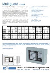
The <strong>MULTIGUARD</strong> AIDALRM system <strong>AA31110D</strong> has been designed to give dual re-assurance indication at the point<br />
of operation. The system components for a six toilet system would be<br />
1 x <strong>AA31110D</strong> Controller<br />
6 x S/1600 Ceiling mounted non-latching Pull Cords with re-assurance LEDs or S/1660RPunits<br />
6 x S/1608 Wall mounted single gang stainless steel reset buttons or S/1679RP units<br />
6 x S/1678 Overdoor Light/Sounder unit (Wall mounted single gang)<br />
The mark resistant decal covers a removable identification panel which can easily be created by a word processor or<br />
graphics package to enable a professional looking facia to be achieved for each installation. Two example blanks are<br />
supplied with these instructions.<br />
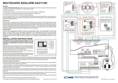
S1678RP Overdoor<br />
Light/Sounder<br />
+<br />
zone 1<br />
A<br />
B<br />
C<br />
D<br />
Cut Diode D5<br />
to drive buzzer<br />
without LED<br />
L-<br />
L+ve<br />
Spare<br />
S/1600<br />
Pull Cord<br />
zone 1<br />
NC<br />
COM<br />
NO<br />
S/1679RP Sounder<br />
LED & Button for<br />
indicating reset.<br />
zone 1<br />
Cut Diode D5<br />
to drive buzzer<br />
without LED<br />
Examples of Overdoor indicators Examples of Call devices Examples of Reset devices<br />
+<br />
A<br />
B<br />
C<br />
D<br />
OPERATION.<br />
When a pull cord is operated its LED, the LED in the S/1678 flashes and a local buzzer in the S1678 sounds to inform<br />
the caller that the call has been transmitted. The zone LED at the panel also flashes and the integral buzzer sounds.<br />
When the call is silenced at the panel the flashing LEDs becomes steady and the local buzzer in the S/1678 silences to<br />
inform the caller that the call has been received and help is on the way. If the caller pulls the cord again the above<br />
sequence is repeated. When help does finally arrive the call can be reset by pressing the reset button S/1608, all LEDs<br />
and buzzers pertaining to that zone, flashing or otherwise, will be extinguished.<br />
POWER SUPPLY<br />
The <strong>AA31110D</strong> is supplied with an integral 13.8vdc power supply rated at 250ma., and a rechargeable 0.7 Ahr standby<br />
battery. The <strong>MULTIGUARD</strong> circuitry has a power requirement of 25ma quiescent and 60ma maximum with all zones<br />
tripped. The integral power supply will therefore support its own six zone electronics plus the external ancilliary<br />
equipment such as over door lights and buzzers. However, it will not support all zones tripped for long periods. The<br />
standby battery will support the system for about six to eight hours in quiescent and approximately 3 hours if two zones<br />
are tripped.<br />
INSTALLATION INSTRUCTIONS<br />
IT IS IMPORTANT THAT THE <strong>MULTIGUARD</strong> IS FIXED TO A FLAT<br />
SURFACE. IF THE BOX DISTORTS IT WILL BE DIFFICULT TO CLIP<br />
THE VARIOUS COMPONENTS TOGETHER TO FORM A SECURE<br />
HOUSING.<br />
Multiple fixing holes are provided to suit the many different standard<br />
fixing centres of various mounting boxes. Choose the appropriate<br />
centres. If a flush rear box is not being used then you should choose<br />
the widest possible centres for the most stable fixing.<br />
Cables may enter through the 20mm holes in the rear of the box or<br />
through the entry slots located on each side.<br />
As the mains power cable is generally the largest it should be routed<br />
into the central compartment and dressed in for connection to the<br />
fused terminal before dressing in the low voltage cables.<br />
<strong>MULTIGUARD</strong> 2000 - 6<br />
Z1<br />
Z2<br />
Z3<br />
Z4<br />
Z5<br />
Z6<br />
197<br />
F3<br />
138<br />
72<br />
Dimensions (mm)<br />
Low voltage cables should be routed into the cable channel between the inner and outer walls of the box. These cables<br />
should only be cut to length when you are ready to terminate them on the PCB assembly. Be sure to leave enough length<br />
to allow the PCB assembly to be removed for access to the fuses and battery terminals at a later stage.<br />
Connection & Power Up sequence.<br />
The <strong>MULTIGUARD</strong> has a short test or verification sequence on power up. You should verify that the unit as supplied is<br />
functioning normally before making any connections.<br />
1. Plug in the battery. The plug is polarised to maintain the correct polarity. Ensure F4 is linked to +ve. The integral<br />
sounder will beep at 1 second intervals. Press the SILENCE button F1. The LED's will flash three times and then reset<br />
automatically. Disconnect the battery.<br />
2. Dress the cables into the cable channel, trim to length and terminate as per the connection diagram. Remove link F4.<br />
Any excess cable should be left in the side channels between the clip and the outer wall. This helps to prevent the clips<br />
deforming.<br />
3. Connect the mains cable from a suitable fused spur to the Live, Neutral & Earth terminals. Ensure the mains fuse is<br />
fitted and the transformer leads (Blue & Yellow) and earth lead (Green) are connected to the PCB.<br />
4. Reconnect the battery, the system will once again go through the test routine. Clip the PCB assembly onto the back<br />
box.<br />
4. Switch on the power at the fused spur. Observe the green Mains On LED.<br />
6. The system can now be tested and the decal marked up and lid clipped into place.<br />
Black<br />
Red<br />
-ve<br />
LED<br />
+ve<br />
BZ<br />
-ve<br />
S1678 Overdoor light<br />
and buzzer on zone 2<br />
Link un-used<br />
inputs to +ve<br />
- + 1 2 3 4 5 6 + + 1 2 3 4 5 6 + + 1 2 3 4 + -<br />
INPUTS<br />
SERIAL<br />
OUTPUT<br />
- + X S D C<br />
ZONE RESETS<br />
RELAY<br />
OUTPUT<br />
FUNCTION<br />
INPUTS<br />
1 2 3 4 5 6 7 8 9 10 11 12 13 14 15 16 -ve +ve<br />
S1608 Non-indicatin<br />
reset button on zone 2<br />
<strong>AA31110D</strong><br />
Complies with Council<br />
Directive 89/336/EEC<br />
<strong>AA31110D</strong><br />
Mains Fuse<br />
Dwg No:60060:2 Iss 1 Page 1 Sept 99 Dwg No:60060:2 Iss 1 Page 2 Sept 99<br />
Black<br />
Red<br />
Blue<br />
White<br />
Yellow<br />
S1605 Call Button<br />
on zone 2<br />
-ve<br />
LED<br />
+ve<br />
NO<br />
COM<br />
NC<br />
+ve 12vdc can be taken from<br />
any +ve terminal on the pcb<br />
they are all common<br />
Zones 1-6 for<br />
buzzer outputs<br />
Zones 1-6 for<br />
LED outputs<br />
<strong>Hoyles</strong> Electronic Developments Ltd<br />
T. 01744 886600 F. 01744 886607 E. sales@hoyles.com W. www.hoyles.com<br />
White<br />
Blue<br />
16vac<br />
Input<br />
Yellow<br />
NC<br />
COM<br />
NO<br />
N<br />
E<br />
L
<strong>MULTIGUARD</strong> <strong>AIDALARM</strong> <strong>AA31110D</strong><br />
GENERAL<br />
The <strong>MULTIGUARD</strong> AIDALRM system <strong>AA31110D</strong> has been designed to give dual re-assurance indication at the point<br />
of operation. The system components for a six toilet system would be<br />
1 x <strong>AA31110D</strong> Controller<br />
6 x S/1600 Ceiling mounted non-latching Pull Cords with re-assurance LEDs or S/1660RPunits<br />
6 x S/1608 Wall mounted single gang stainless steel reset buttons or S/1679RP units<br />
6 x S/1678 Overdoor Light/Sounder unit (Wall mounted single gang)<br />
The mark resistant decal covers a removable identification panel which can easily be created by a word processor or<br />
graphics package to enable a professional looking facia to be achieved for each installation. Two example blanks are<br />
supplied with these instructions.<br />
S1678RP Overdoor<br />
Light/Sounder<br />
+<br />
zone 1<br />
A<br />
B<br />
C<br />
D<br />
Cut Diode D5<br />
to drive buzzer<br />
without LED<br />
L-<br />
L+ve<br />
Spare<br />
S/1600<br />
Pull Cord<br />
zone 1<br />
NC<br />
COM<br />
NO<br />
S/1679RP Sounder<br />
LED & Button for<br />
indicating reset.<br />
zone 1<br />
Cut Diode D5<br />
to drive buzzer<br />
without LED<br />
Examples of Overdoor indicators Examples of Call devices Examples of Reset devices<br />
+<br />
A<br />
B<br />
C<br />
D<br />
OPERATION.<br />
When a pull cord is operated its LED, the LED in the S/1678 flashes and a local buzzer in the S1678 sounds to inform<br />
the caller that the call has been transmitted. The zone LED at the panel also flashes and the integral buzzer sounds.<br />
When the call is silenced at the panel the flashing LEDs becomes steady and the local buzzer in the S/1678 silences to<br />
inform the caller that the call has been received and help is on the way. If the caller pulls the cord again the above<br />
sequence is repeated. When help does finally arrive the call can be reset by pressing the reset button S/1608, all LEDs<br />
and buzzers pertaining to that zone, flashing or otherwise, will be extinguished.<br />
POWER SUPPLY<br />
The <strong>AA31110D</strong> is supplied with an integral 13.8vdc power supply rated at 250ma., and a rechargeable 0.7 Ahr standby<br />
battery. The <strong>MULTIGUARD</strong> circuitry has a power requirement of 25ma quiescent and 60ma maximum with all zones<br />
tripped. The integral power supply will therefore support its own six zone electronics plus the external ancilliary<br />
equipment such as over door lights and buzzers. However, it will not support all zones tripped for long periods. The<br />
standby battery will support the system for about six to eight hours in quiescent and approximately 3 hours if two zones<br />
are tripped.<br />
INSTALLATION INSTRUCTIONS<br />
IT IS IMPORTANT THAT THE <strong>MULTIGUARD</strong> IS FIXED TO A FLAT<br />
SURFACE. IF THE BOX DISTORTS IT WILL BE DIFFICULT TO CLIP<br />
THE VARIOUS COMPONENTS TOGETHER TO FORM A SECURE<br />
HOUSING.<br />
Multiple fixing holes are provided to suit the many different standard<br />
fixing centres of various mounting boxes. Choose the appropriate<br />
centres. If a flush rear box is not being used then you should choose<br />
the widest possible centres for the most stable fixing.<br />
Cables may enter through the 20mm holes in the rear of the box or<br />
through the entry slots located on each side.<br />
As the mains power cable is generally the largest it should be routed<br />
into the central compartment and dressed in for connection to the<br />
fused terminal before dressing in the low voltage cables.<br />
<strong>MULTIGUARD</strong> 2000 - 6<br />
Z1<br />
Z2<br />
Z3<br />
Z4<br />
Z5<br />
Z6<br />
197<br />
F3<br />
138<br />
72<br />
Dimensions (mm)<br />
Low voltage cables should be routed into the cable channel between the inner and outer walls of the box. These cables<br />
should only be cut to length when you are ready to terminate them on the PCB assembly. Be sure to leave enough length<br />
to allow the PCB assembly to be removed for access to the fuses and battery terminals at a later stage.<br />
Connection & Power Up sequence.<br />
The <strong>MULTIGUARD</strong> has a short test or verification sequence on power up. You should verify that the unit as supplied is<br />
functioning normally before making any connections.<br />
1. Plug in the battery. The plug is polarised to maintain the correct polarity. Ensure F4 is linked to +ve. The integral<br />
sounder will beep at 1 second intervals. Press the SILENCE button F1. The LED's will flash three times and then reset<br />
automatically. Disconnect the battery.<br />
2. Dress the cables into the cable channel, trim to length and terminate as per the connection diagram. Remove link F4.<br />
Any excess cable should be left in the side channels between the clip and the outer wall. This helps to prevent the clips<br />
deforming.<br />
3. Connect the mains cable from a suitable fused spur to the Live, Neutral & Earth terminals. Ensure the mains fuse is<br />
fitted and the transformer leads (Blue & Yellow) and earth lead (Green) are connected to the PCB.<br />
4. Reconnect the battery, the system will once again go through the test routine. Clip the PCB assembly onto the back<br />
box.<br />
4. Switch on the power at the fused spur. Observe the green Mains On LED.<br />
6. The system can now be tested and the decal marked up and lid clipped into place.<br />
Black<br />
Red<br />
-ve<br />
LED<br />
+ve<br />
BZ<br />
-ve<br />
S1678 Overdoor light<br />
and buzzer on zone 2<br />
Link un-used<br />
inputs to +ve<br />
- + 1 2 3 4 5 6 + + 1 2 3 4 5 6 + + 1 2 3 4 + -<br />
INPUTS<br />
SERIAL<br />
OUTPUT<br />
- + X S D C<br />
ZONE RESETS<br />
RELAY<br />
OUTPUT<br />
FUNCTION<br />
INPUTS<br />
1 2 3 4 5 6 7 8 9 10 11 12 13 14 15 16 -ve +ve<br />
S1608 Non-indicatin<br />
reset button on zone 2<br />
<strong>AA31110D</strong><br />
Complies with Council<br />
Directive 89/336/EEC<br />
<strong>AA31110D</strong><br />
Mains Fuse<br />
Dwg No:60060:2 Iss 1 Page 1 Sept 99 Dwg No:60060:2 Iss 1 Page 2 Sept 99<br />
Black<br />
Red<br />
Blue<br />
White<br />
Yellow<br />
S1605 Call Button<br />
on zone 2<br />
-ve<br />
LED<br />
+ve<br />
NO<br />
COM<br />
NC<br />
+ve 12vdc can be taken from<br />
any +ve terminal on the pcb<br />
they are all common<br />
Zones 1-6 for<br />
buzzer outputs<br />
Zones 1-6 for<br />
LED outputs<br />
<strong>Hoyles</strong> Electronic Developments Ltd<br />
T. 01744 886600 F. 01744 886607 E. sales@hoyles.com W. www.hoyles.com<br />
White<br />
Blue<br />
16vac<br />
Input<br />
Yellow<br />
NC<br />
COM<br />
NO<br />
N<br />
E<br />
L