The Camera Obscura - AstroMedia
The Camera Obscura - AstroMedia
The Camera Obscura - AstroMedia

Create successful ePaper yourself
Turn your PDF publications into a flip-book with our unique Google optimized e-Paper software.
Section B<br />
<strong>The</strong> outer lens tube<br />
<strong>The</strong> outer lens tube serves as a guide for<br />
the inner lens tube, that will not be built until<br />
Section D. <strong>The</strong> inner tube can be moved<br />
forwards and backwards inside the outer<br />
tube, in order to adjust the position of the<br />
lens for focusing objects at different<br />
distances.<br />
Step 4: Detach the outer lens tube [B1,<br />
sheet 5] from the cardboard and bend back<br />
all eight of the scored lines. When the<br />
edges of the two half segments at the ends<br />
of the card piece press against each other,<br />
this gives a short eight-sided tube with a<br />
black interior. <strong>The</strong> small glue tabs with grey<br />
markings are the foot brackets which will be<br />
used to attach the tube inside the front wall.<br />
<strong>The</strong>y are all bent forwards, outwards from<br />
the interior of the tube. To make the folded<br />
piece of card into a strong eight-sided tube,<br />
you need the connecting piece [B2, sheet<br />
7]. Stick it on the outside on one halfsegment<br />
so that exactly half of it protrudes,<br />
and then onto the other. This works<br />
particularly well if you press the tube flat<br />
with the two edges touching each other<br />
without a gap. Ensure there is about one<br />
millimetre clearance between the<br />
connecting piece and the foot brackets.<br />
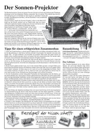
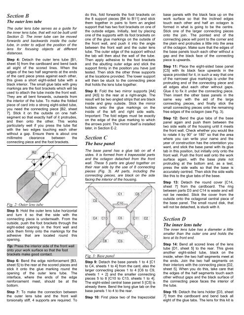
Fig. 2: Outer lens tube<br />
Step 5: Hold the outer lens tube horizontal<br />
and turn it so that the side with the<br />
connecting piece is underneath. From the<br />
outside, push the foot brackets through the<br />
eight-sided opening in the front wall and<br />
stick them firmly onto the markings for the<br />
adhesive that are located round this<br />
opening.<br />
Tip: Press the interior side of the front wall<br />
onto your work surface so that the foot<br />
brackets make good contact.<br />
Step 6: Bend the edge reinforcement [B3,<br />
sheet 5] to the rear at the scored places and<br />
stick it onto the glue marking round the<br />
opening of the outer lens tube. <strong>The</strong><br />
interface, where the ends of the edge<br />
reinforcement meet, should be at the<br />
bottom.<br />
Step 7: To make the connection between<br />
the outer lens tube and the front wall<br />
torsionally stiff, 4 supports are required. To<br />
do this, fold forwards the foot brackets on<br />
the 8 support pieces [B4 to B11] and stick<br />
them together in pairs to form an angled<br />
support that has two foot brackets on one of<br />
the outside edges. Initially, test by placing<br />
one of the supports with its foot brackets on<br />
one of the glue markings on the outside of<br />
the front wall, and push it into the angle<br />
between the front wall and the outer lens<br />
tube. <strong>The</strong> outer edge of the support without<br />
the tab will then abut the wall of the tube.<br />
<strong>The</strong>n apply adhesive to the foot brackets<br />
and the abutting outer edge and stick the<br />
support firmly in the position you have just<br />
tested. <strong>The</strong>n stick the other three supports<br />
at the locations provided. <strong>The</strong> lower support<br />
will then be stuck to the connecting piece<br />
that holds the lens tube together.<br />
Step 8: Fold the two mirror supports [A4]<br />
and [A5] to the rear at a right-angle. <strong>The</strong><br />
result will be two angled strips that are black<br />
inside and grey outside. Stick the mirror<br />
holders onto the glue markings on the<br />
inside of the left and right side walls.<br />
Important: <strong>The</strong> fold edges must be exactly<br />
on the edge of the glue marking to which<br />
the arrows point. <strong>The</strong> mirror itself is installed<br />
later, in Section E-2.<br />
Section C<br />
<strong>The</strong> base panel<br />
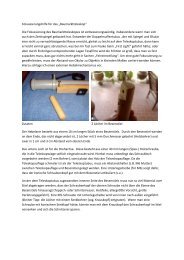
<strong>The</strong> base panel has a glue tab on all 4<br />
sides. It is formed from 4 trapezoidal parts<br />
and the octagon detached from the front<br />
wall. <strong>The</strong>se 5 parts are glued together on<br />
their rear side by the use of 8 connecting<br />
pieces (Fig. 3). All parts, including the<br />
connecting pieces, are black on the side<br />
facing the interior of the housing.<br />
Fig. 3: Base panel<br />
Step 9: Detach the base panels 1 to 4 [C1<br />
to C4, sheets 1 to 4] from the card, also the<br />
larger connecting pieces 1 to 4 [C6 to C9,<br />
sheets 1 + 2] and the smaller connecting<br />
pieces 5 to 8 [C10 to C13, sheets 1 to 4].<br />
<strong>The</strong> eight-sided central base panel 5 [C5] is<br />
already there. Bend the long glue tab on the<br />
base panels 1 to 4 to the rear.<br />
Step 10: First place two of the trapezoidal<br />
base panels with the black face up on the<br />
work surface so that the inclined edges<br />
touch each other and half an octagon is<br />
formed in what is going to be the centre.<br />
Stick one of the larger connecting pieces<br />
onto the join. <strong>The</strong> pointed end of the<br />
connecting piece will point to the corner and<br />
the plain end protrudes a little into the area<br />
of the octagon. Make sure that the edges of<br />
the base panels touch each other without a<br />
gap and the black face of the connecting<br />
piece is upwards.<br />
Step 11: Place the eight-sided base panel<br />
[C5] with its black face upwards in the<br />
space provided for it, in such a way that one<br />
of the narrower glue markings is under the<br />
protruding end of the connecting piece and<br />
all edges abut each other without gaps.<br />
Glue it to fix it under the connecting piece.<br />
<strong>The</strong>n insert the other base panels in the<br />
same way with the aid of the large<br />
connecting pieces, and finally stick the<br />
small connecting pieces onto the remaining<br />
free edges of the octagon (see Fig. 3).<br />
Step 12: Bend the glue tabs of the base<br />
panel again and push them between the<br />
two side walls of the housing until it meets<br />
the front wall. Check whether you would like<br />
to rotate it by 90° or 180° so that the area<br />
where you can write your name and the<br />
year of construction has the orientation you<br />
want, and stick the base panel with its glue<br />
tab in this position, but initially only onto the<br />
front wall. Push the front wall onto the work<br />
surface again, with the base plate not<br />
protruding at the bottom and, as a test,<br />
press the side walls so that the base is<br />
accurately centred. <strong>The</strong>n stick the side walls<br />
like this to the glue tabs of the base.<br />
Step 13: Detach the round cover [C14,<br />
sheet 7] from the cardboard. <strong>The</strong> ring<br />
between parts D3 and C14 is waste and will<br />
not be needed. Stick the cover from the<br />
outside onto the octagonal central piece of<br />
the base panel. <strong>The</strong> small round disk, that<br />
will not be detached, is stuck with it.<br />
Section D<br />
<strong>The</strong> inner lens tube<br />
<strong>The</strong> inner lens tube has a diameter a little<br />
smaller than the outer one and holds the<br />
lens at its front end.<br />
Step 14: Bend all scored lines of the lens<br />
tube [D1, sheet 5] to the rear. This gives<br />
another eight-sided tube, black on the<br />
inside, when the two half segments meet at<br />
the ends. Join the two half segments on<br />
their interiors with the connecting piece [D2,<br />
sheet 5]. When you do this, take care that<br />
the edges of the half segments touch each<br />
other without gaps and the black surface of<br />
the connecting piece faces the interior of<br />
the tube.<br />
Step 15: Detach the lens holder [D3, sheet<br />
7] from the cardboard and bend back all<br />
eight of the glue tabs. <strong>The</strong> lens for this kit is