Sealing Rings for Dynamic Seals
Sealing Rings for Dynamic Seals
Sealing Rings for Dynamic Seals

Create successful ePaper yourself
Turn your PDF publications into a flip-book with our unique Google optimized e-Paper software.
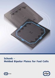
<strong>Sealing</strong> <strong>Rings</strong><br />
<strong>for</strong> <strong>Dynamic</strong> <strong>Seals</strong><br />
Business Unit Tribology
Table of Contents<br />
Page<br />
Characteristic Properties ..................................................................................... 3<br />
• Characteristic Properties <strong>for</strong> Seal Material used in <strong>Dynamic</strong> <strong>Seals</strong> ............................. 3<br />
• <strong>Sealing</strong> <strong>Rings</strong> <strong>for</strong> Mechanical <strong>Seals</strong> .................................................................. 3<br />
<strong>Sealing</strong> <strong>Rings</strong> <strong>for</strong> Mechanical <strong>Seals</strong> ....................................................................... 4<br />
• a) Grade Selection ....................................................................................... 5<br />
• b) Application Limits ................................................................................... 6<br />
• c) Counterface Materials ............................................................................... 7<br />
• d) Machining of Sliding Surfaces Roughness – Surface Flatness ............................. 7<br />
• e) Pressure Tightness of Carbon <strong>Sealing</strong> <strong>Rings</strong> .................................................. 8<br />
• f) Installation of Carbon <strong>Sealing</strong> <strong>Rings</strong> ............................................................. 8<br />
• g) Fields of Application and Grade Recommendations ......................................... 9<br />
Carbon <strong>Seals</strong> <strong>for</strong> Steam Head <strong>Seals</strong> ....................................................................... 10<br />
• Carbon <strong>Seals</strong> <strong>for</strong> Steam Head <strong>Seals</strong> ................................................................. 10<br />
• Grade Recommendations ............................................................................. 10<br />
<strong>Sealing</strong> <strong>Rings</strong> <strong>for</strong> Ball Valves ............................................................................... 11<br />
<strong>Sealing</strong> <strong>Rings</strong> <strong>for</strong> Radial <strong>Seals</strong> .............................................................................. 12<br />
• 1) Gap <strong>Seals</strong> ............................................................................................. 13<br />
• Fields of Application ................................................................................... 13<br />
• a) Multisegment <strong>Rings</strong> ................................................................................. 13<br />
• b) Metal Clad Carbon <strong>Rings</strong> ........................................................................... 14<br />
• c) Labyrinth <strong>Rings</strong> ....................................................................................... 15<br />
• 2) Contact <strong>Seals</strong> ......................................................................................... 16<br />
• 3) Grade Selection ..................................................................................... 16<br />
• Mating Materials ........................................................................................ 17<br />
• 4) Back-up <strong>Rings</strong> ........................................................................................ 17<br />
• 5) Design Recommendations ......................................................................... 17<br />
• 6) Design Examples <strong>for</strong> Multisegment Carbon <strong>Sealing</strong> <strong>Rings</strong> ................................. 18<br />
2
Characteristic Properties<br />
Characteristic Properties <strong>for</strong><br />
Seal Material used in <strong>Dynamic</strong> <strong>Seals</strong><br />
The following characteristic<br />
properties of carbon and graphite<br />
materials have opened up wide fields<br />
of application <strong>for</strong> carbon and graphite<br />
sealing rings, e. g. in high and low<br />
temperature technology, in chemical<br />
and petrochemical industries, <strong>for</strong><br />
the processing of food stuffs,<br />
pharmaceutics and cosmetics, in<br />
pumps, compressors and turbines,<br />
in aircraft and automobile<br />
construction, in shipbuilding, in<br />
the paper processing industry, in air<br />
conditioning technology, in household<br />
appliances and in reactor<br />
technology.<br />
• Sliding and dry running capacity,<br />
low coefficient of friction<br />
• Wear resistance<br />
• Chemical resistance<br />
• Temperature resistance<br />
• Good thermal conductivity<br />
• Outstanding resistance<br />
to temperature cycling<br />
• Excellent dimensional stability<br />
• High fatigue resistance<br />
• Favourable ratio strength/density<br />
• No welding risk, contrary to<br />
metals when used as mating<br />
materials.<br />
Please find further in<strong>for</strong>mation on<br />
Schunk carbon and graphite materials<br />
<strong>for</strong> mechanical applications at<br />
www.schunk-tribo.com:<br />
“Chemical Resistance”<br />
“General In<strong>for</strong>mation; Properties,<br />
Application as Sliding Material,<br />
Design Recommendations”.<br />
<strong>Sealing</strong> <strong>Rings</strong><br />
<strong>for</strong> Mechanical <strong>Seals</strong><br />
The mechanical seal can be regarded<br />
as the main high-quality sealing<br />
element in use <strong>for</strong> the sealing of<br />
rotary shafts.<br />
This rapid development of the<br />
mechanical seal as a machine<br />
element has only been possible<br />
through the continuous development<br />
of seal designs and through<br />
the systematic development of new<br />
and improved sealing ring materials.<br />
This also includes the further development<br />
of carbon-graphite materials<br />
by Schunk Kohlenstofftechnik, which<br />
has made it possible to match<br />
increasingly severe operating<br />
conditions and thus the stricter<br />
requirements imposed on sealing<br />
ring materials.<br />
In the development of new and improved<br />
grades of carbon <strong>for</strong> sealing<br />
rings not only the required material<br />
properties, but also the question of<br />
cost had to be taken into account,<br />
particularly <strong>for</strong> sealing rings in lowpriced<br />
mass-produced seals.<br />
Schunk Kohlenstofftechnik’s material<br />
range extends from synthetic resinbonded<br />
carbon grades through<br />
carbon-redensified carbon graphite<br />
and electrographite grades, carbon<br />
graphite and electrographite grades<br />
with various synthetic resin and<br />
metal impregnations to high<br />
strength electrographite grades<br />
with special impregnations to<br />
improve the oxidation resistance or<br />
the dry running capacity.<br />
The properties of synthetic resinbonded<br />
carbon grades have been<br />
improved considerably compared<br />
to carbon containing resin molding<br />
compounds. These grades are<br />
particularly suitable <strong>for</strong> the<br />
pressing-to-size of rings, even in<br />
fairly complicated designs, <strong>for</strong><br />
mass-produced seals. In addition,<br />
a range of carbon graphite grades<br />
with the above mentioned impregnations<br />
are available which are also<br />
suitable <strong>for</strong> the pressing-to-size<br />
or partially pressing-to-size <strong>for</strong><br />
mass-produced seals.<br />
3
<strong>Sealing</strong> <strong>Rings</strong> <strong>for</strong> Mechanical <strong>Seals</strong><br />
Mechanical seals are mainly used<br />
<strong>for</strong> sealing between liquids and<br />
gases. It should be noted that,<br />
with carbon seal rings, even liquids<br />
with low hydrodynamic lubricating<br />
capacity provide sufficient<br />
lubricating effect.<br />
The sealing of gases and the dry<br />
running that arises from this is<br />
possible at low sliding speeds with<br />
carbon sealing rings e. g. in agitator<br />
seals, provided that the wear rate<br />
is sufficiently low.<br />
For the sealing of gases at high<br />
running speeds the use of carbon<br />
seal rings in so called gas seals is<br />
also common, provided that the<br />
design of the seal ensures that<br />
contact between the sliding<br />
surfaces can only occur at starting<br />
and stopping the machine. During<br />
normal running, the gas pressure<br />
ensures contact free operation of<br />
the sliding surfaces. <strong>Sealing</strong> between<br />
gases is carried out otherwise with<br />
double-acting mechanical seals and<br />
a sealing liquid, the sealing liquid<br />
serving as a lubricant <strong>for</strong> the<br />
sliding faces and <strong>for</strong> the dissipation<br />
of the frictional heat.<br />
Unbalanced mechanical seal<br />
Balanced mechanical seal<br />
Schematic representation<br />
of mechanical seal designs<br />
Double-acting mechanical seal<br />
4
a) Grade Selection<br />
It must be said that it is impossible to cover all service conditions<br />
with one carbon graphite material.<br />
General Indications on Grades:<br />
Synthetic resin-bonded<br />
carbon grades<br />
Examples: FF521<br />
Carbon redensified<br />
carbon grades<br />
Examples: FH82Y5<br />
Synthetic resin-impregnated<br />
carbon grades<br />
Examples: FH44Z5, FH42Z5, FH82Z5<br />
Metal impregnated<br />
carbon grades<br />
Examples: FH42A, FH82A<br />
Electrographite and<br />
carbon graphite<br />
Examples: FH44Z2, FE45Y2<br />
Examples of special materials:<br />
FH71ZH5, FH71A<br />
Wet running, low running speeds<br />
and loads, low chemical requirements<br />
Wet running, average running speeds<br />
and loads, highest chemical requirements<br />
Wet running, average to high running speeds<br />
and loads, high chemical requirements<br />
Wet running, up to highest running<br />
speeds and loads, limited chemical requirements<br />
Dry running at low speeds<br />
Application in an absolutely dry environment<br />
Seal rings<br />
<strong>for</strong> compressors<br />
5
) Application Limits<br />
Running speed:<br />
70 m/s max.<br />
Pressure difference:<br />
160 bar max.<br />
Sliding pressure:<br />
10 – 200 N/cm 2<br />
generally < 50 N/cm 2<br />
Product of pressure and speed:<br />
p•v max.<br />
= 12,500 N/cm 2 •m/s<br />
The sealing ring wear is influenced<br />
much more by the sliding pressure<br />
than the sliding speed.<br />
For many years Schunk Kohlenstofftechnik<br />
has carried out wear tests<br />
with standard and new developed<br />
grades. For such tests, 8 test rigs<br />
with 16 testing positions are used.<br />
Test rigs <strong>for</strong> mechanical seals<br />
Testing stand <strong>for</strong> blister tests with high<br />
viscosity oils as the medium to be sealed off<br />
6
c) Counterface Materials<br />
The choice of materials <strong>for</strong> the<br />
mating component is of decisive<br />
importance <strong>for</strong> the operation of a<br />
mechanical seal. Three categories<br />
of mating materials <strong>for</strong> sliding rings<br />
of carbon graphite materials are<br />
summarized in the following table:<br />
Counterface Materials<br />
Suitable<br />
• Cast iron<br />
• Cast chrome steel<br />
• Hardened chrome steel<br />
• Tungsten carbide<br />
• Chromium oxide<br />
(plasma coated)<br />
• Silicon carbide materials<br />
• Sintered ceramic (AI 2 O 3 )<br />
(only <strong>for</strong> wet running)<br />
• Carbon graphite materials<br />
• Silicon carbide/graphite<br />
composite material<br />
Limited use<br />
• Chrome nickel steel<br />
• Austenitic cast iron<br />
• Stainless sintered steel<br />
(impregnated with polyester resin)<br />
• Stellite<br />
• PTFE compounds<br />
• Non ferrous metals<br />
d) Machining of Sliding<br />
Surfaces Roughness –<br />
Surface Flatness<br />
The machining quality of the sliding<br />
surfaces is decisive <strong>for</strong> the seal<br />
or leakage and the wear of the<br />
sliding rings. There<strong>for</strong>e, the sliding<br />
surfaces of seal rings have to be<br />
lapped, polished or superfinished.<br />
Roughness<br />
of Sliding Surfaces<br />
Carbon faces:<br />
Ra 0.2 – 0.4 µm<br />
Carbon sliding faces run-in rapidly<br />
on the counterfaces covering them<br />
with a graphite layer.<br />
Lower roughness of the counterface<br />
impedes a rapid development of<br />
this friction and wear reducing,<br />
graphite layer.<br />
Lower roughness of the counterfaces<br />
prevents from a fast <strong>for</strong>mation<br />
of this friction and wear reducing<br />
transfer layer.<br />
Surface Flatness<br />
of the Sliding Faces<br />
Outer diameter of the sliding faces<br />
80 mm<br />
+ 1 light band<br />
(approx. 0.3 µm)<br />
<strong>for</strong> every 30 – 50 mm<br />
increase in diameter.<br />
The inspection of the surface<br />
flatness is effected by means of an<br />
optical glass and monochromatic<br />
light in an interference inspection<br />
apparatus, or with a laser<br />
interferometer.<br />
Unsuitable<br />
• Aluminium<br />
• Aluminium alloys<br />
(even if anodised)<br />
Sliding surface with imperfect flatness<br />
Perfectly flat surface<br />
7
e) Pressure Tightness of<br />
Carbon <strong>Sealing</strong> <strong>Rings</strong><br />
Sliding rings made of redensified or<br />
impregnated carbon graphite<br />
material are impervious to liquids<br />
and gas.<br />
An inspection of the pressure<br />
tightness can be per<strong>for</strong>med at<br />
3, 5 or 10 bar.<br />
f) Installation of<br />
Carbon <strong>Sealing</strong> <strong>Rings</strong><br />
Usually, carbon sliding rings are<br />
installed in a push-fit seating over<br />
O-rings and in rubber or plastic<br />
sleeves, antirotation locking being<br />
provided <strong>for</strong> in each case.<br />
Adhesive bonding is customary <strong>for</strong><br />
installation in metal holders or<br />
metal bellows. The adhesive must<br />
be suited to the chemical and<br />
thermal requirements. Special<br />
attention must be given to the<br />
pressure tightness of the joint.<br />
The same applies to press-in and<br />
shrink-in fits. Here, the following<br />
criteria are important. It is important<br />
to maintain tight dimensional<br />
tolerances particulary shape<br />
tolerances such as concentricity<br />
and conicity of both the bore and<br />
outside diameter.<br />
Press-in fit: H7/s6<br />
Shrink-in fits: H7/x8–zb8<br />
The required crossover tolerance<br />
and shrinkage temperature <strong>for</strong><br />
shrinkage fit are dependent on the<br />
holding material and operating<br />
temperature. Because of the<br />
changes in shape that occur during<br />
shrinking in, the flatness of the<br />
sliding surfaces can only be<br />
achieved by remachining after<br />
shrinking in.<br />
Coarse structure X-ray<br />
photograph of<br />
metal-impregnated<br />
carbon sealing rings<br />
Due to the lower shrinking stress<br />
at operating temperature, compared<br />
to room temperature, the sliding<br />
surface is no longer as flat over its<br />
whole width at operating temperature<br />
as it is at room temperature,<br />
resulting in a certain leakage until<br />
the running in of the sliding surfaces.<br />
Carbon sliding rings with metal sleeve<br />
8
g) Fields of Application<br />
and Grade<br />
Recommendations<br />
The following table of application<br />
fields <strong>for</strong> mechanical seals with carbon<br />
graphite sliding rings cannot<br />
be comprehensive.<br />
The indication of the Schunk grades<br />
<strong>for</strong> the various applications have to<br />
be considered as recommendations,<br />
based on success in service.<br />
ln special cases, other grades may<br />
be more suitable. Please contact<br />
our application specialists.<br />
Fields of Application<br />
Grade Recommendations<br />
<strong>for</strong> Mechanical <strong>Seals</strong><br />
<strong>for</strong> Carbon Sliding <strong>Rings</strong><br />
Cold water pumps<br />
FH421Z5, FH421A<br />
Hot water pumps<br />
FH82ZH5, FH82A<br />
Industrial water pumps<br />
FH42Z5, FH82Z5<br />
Feed water pumps<br />
FH82ZH5, FH82A, SiC30<br />
Automobile cooling water pumps FH421Z5, FH421A, FF541<br />
Compressors <strong>for</strong> automobile<br />
air conditioning equipment<br />
FH421A<br />
Refrigeration compressors<br />
FH82A, FH82ZH5, SiC30<br />
Feed pumps <strong>for</strong> fuel and fuel oil FH42A, FH82A<br />
Oil-burner feed pumps<br />
FH421A, FF521<br />
Dishwasher lye pumps<br />
FH421Z5<br />
For aircraft construction<br />
FE679Q, FH42AR, SiC30<br />
In ship building stern<br />
Tube seals surface crafts<br />
FH429A, FH829A, FH829Z5<br />
and submarines<br />
Bilge pumps<br />
FH42Z5, FH82Z5<br />
Pumps and installations in the<br />
food industry<br />
FH42Z5, FH82Z5<br />
Chemical pumps<br />
FH44Z5, FH42Z5, FH82Z5,<br />
FH82Y5, FE45Y2, FE45Z5<br />
Pumps <strong>for</strong> petrochemistry<br />
FH42A, FH82A<br />
Agitators wet running FH42Z5, FH82Z5, FH42A, FH82A<br />
dry running<br />
FH71Z5<br />
Centrifuges<br />
FH44Z5, FH42Z5<br />
Compressors<br />
FH82A, FH82ZH5<br />
Thermal oil pumps<br />
FH42A, FH82A<br />
Pumps <strong>for</strong> power stations<br />
FH82Z5, FH82ZH5, FH82A, SiC30<br />
Primary cooling pumps <strong>for</strong><br />
nuclear power stations<br />
FH829Z5, FH829ZH5, SiC 30<br />
Water turbines<br />
FH27Z2, FH42, FH71ZH5<br />
Pumps <strong>for</strong> liquefied gasses<br />
FH42A, FH82A, FE45A<br />
Gas seal<br />
9
Kugelhahndichtringe<br />
Carbon <strong>Seals</strong> <strong>for</strong> Steam Header <strong>Seals</strong><br />
Carbon <strong>Seals</strong> <strong>for</strong> Steam Header <strong>Seals</strong><br />
The steam header seal, or in more<br />
general terms the feeder head<br />
seal, represents a special <strong>for</strong>m of<br />
mechanical seal.<br />
When steam, hot or cooling water<br />
and thermal oil are fed to rotating<br />
rolls and drums, vibrations, wobbling<br />
and oscillatory movements can<br />
occur as well as the rotary motion.<br />
There<strong>for</strong>e the design of the feeder<br />
head seal must permit certain<br />
angular movements. In most cases,<br />
this is achieved through the use of<br />
carbon sealing rings having a<br />
convex or concave sliding surface.<br />
Feeder head seals, e. g. in the paper<br />
and pulp industry, have to run<br />
continuously and maintenance-free<br />
<strong>for</strong> long periods of time although<br />
the carbon graphite seal rings are<br />
subject to mixed friction, only<br />
lubricated by steam or even dry<br />
running.<br />
Steam header seal<br />
Usually the running speed with<br />
values of < 0.1 m/s is low, the load,<br />
however, can exceed 150 N/cm 2 .<br />
Due to the resulting friction heat,<br />
the temperature in the sealing gap<br />
may exceed the saturation point of<br />
the steam and, consequently, there<br />
will be dry running.<br />
It is there<strong>for</strong>e recommended to<br />
avoid setting the load too high and<br />
to accept a slight leakage of the<br />
non-toxic steam.<br />
Spring load: 1–3 N/cm 2<br />
Feeder head seal<br />
Grade Recommendations<br />
Steam:<br />
FH27S, FH42, FH42A, FH44Y2,<br />
FH27Z2, FH44Z2<br />
Cold water:<br />
FH44Z5, FH42Z5<br />
Hot water:<br />
FH42A, FH44ZH5, FH42ZH5<br />
Thermal oils:<br />
FH42A, FH82A<br />
Most of the indications given in the<br />
<strong>for</strong>egoing chapter “<strong>Sealing</strong> <strong>Rings</strong>”<br />
are also valid.<br />
Carbon sealing rings<br />
<strong>for</strong> steam header seals<br />
10
<strong>Sealing</strong> <strong>Rings</strong> <strong>for</strong> Ball Valves<br />
<strong>Sealing</strong> <strong>Rings</strong><br />
<strong>for</strong> Ball Valves<br />
Ball valve seals of carbon graphite<br />
material are in use <strong>for</strong> fire-safe<br />
ball-valves <strong>for</strong> oil refineries and oil<br />
tankers and <strong>for</strong> high temperature<br />
ball valves <strong>for</strong> chemical industries.<br />
Seal rings of carbon graphite<br />
material are in use <strong>for</strong> the sealing<br />
of hot steam and gas, i. e. beyond<br />
the capacities of conventional<br />
materials such as PTFE compounds<br />
etc.<br />
Roughness of counterfaces:<br />
R t = < 1.5 µm<br />
Grade recommendations:<br />
FE45A, FH42A<br />
Ball valve seal<br />
11
<strong>Sealing</strong> <strong>Rings</strong> <strong>for</strong> Radial <strong>Seals</strong><br />
Multi part carbon ring<br />
<strong>for</strong> radial shaft sealing<br />
Because of their characteristic<br />
properties (see chapter 1) carbon/<br />
graphite sealing rings have been<br />
successfully used <strong>for</strong> many years in<br />
radial seals, both with rotary and<br />
oscillatory motions.<br />
Apart from carbon sealing rings<br />
encased in metal, multipart carbon<br />
sealing rings composed of segments<br />
are mainly used <strong>for</strong> radial seals.<br />
The multi-part construction is<br />
necessary, because carbon and<br />
graphite materials cannot de<strong>for</strong>m<br />
elastically like other sealing<br />
materials <strong>for</strong> radial seals. In addition,<br />
the multipart construction<br />
simplifies assembly.<br />
Depending on the size of the rings,<br />
they are divided into 3, 4, 6, 8, 12<br />
or more segments. In order to<br />
secure an optimal assembly and<br />
thus a maximum sealing effect<br />
the individual ring segments are<br />
numbered. Multi-part carbon sealing<br />
rings are pressed against the<br />
shaft or piston rod by garter<br />
springs.<br />
Recommended surface pressure:<br />
1 – 1.5 N/cm 2<br />
Garter springs out of stainless steel<br />
1.4310 have proved satisfactory.<br />
Fracture segmented ring (patented)<br />
12
Dimensioning of Multi-part Carbon/<br />
Graphite <strong>Sealing</strong> <strong>Rings</strong><br />
D =<br />
1.2 to 1.5 x d<br />
b min<br />
= 8 mm with butt and overlapped joint<br />
b min<br />
= 10 mm with overlapped mortise joint<br />
h ~ 0.15 x d<br />
h min<br />
= 6 mm with butt and overlapped joint<br />
h min<br />
= 8 mm with overlapped mortise joint<br />
r = Outside diamter of spring<br />
2<br />
+ 0.3 to 0.5 mm<br />
s ~ depending on the type of seal, the shaft<br />
diameter and number of segments in the ring<br />
1) Gap <strong>Seals</strong><br />
Gap seals are used with both<br />
rotating and reciprocating motions.<br />
A gap seal is always preferable to<br />
a contact seal if excessive wear is<br />
to be expected with a contact seal<br />
because of the operating conditions.<br />
This mainly applies <strong>for</strong> high sliding<br />
speeds and high loads where, in<br />
the case of a contact seal, excessive<br />
heating can occur at the sealing<br />
faces, resulting in excessive wear.<br />
Both one piece carbon rings,<br />
encased in metal holders, and<br />
segmented sealing rings are used<br />
in gap seals.<br />
Fields of Application<br />
Typical fields of application <strong>for</strong><br />
gap seals are steam turbines,<br />
piston rod glands of oil-free piston<br />
compressors, screw type<br />
compressors and axial-flow<br />
compressors in general.<br />
a) Multisegment <strong>Rings</strong><br />
With multisegment carbon graphite<br />
sealing rings, tight tolerances <strong>for</strong><br />
assembly are not necessary.<br />
When installed, the rings must have<br />
a certain clearance at the segment<br />
joints, so that, under the pressure<br />
of the garter spring, they work<br />
initially as contact seals.<br />
It is only after slight wear during<br />
running-in that the joint clearance<br />
becomes zero and the seal can<br />
run practically as a gap seal,<br />
with minimum gap losses and<br />
consequently high sealing effect.<br />
The adjustable orientation of<br />
multi-segment rings in chambers<br />
is advantageous <strong>for</strong> compensation<br />
of radial shaft displacement.<br />
Different carbon ring segments<br />
With butt jointed sealing rings it is<br />
preferable to arrange two rings in a<br />
chamber with the joints staggered<br />
in relation to one another in order<br />
to achieve a good axial seal. Even<br />
with carbon sealing rings with<br />
overlapped or overlapped mortise<br />
joints, this arrangement of the<br />
rings in pairs in chambers gives an<br />
improvement in axial sealing.<br />
For rotation prevention the rings<br />
are usually pinned to one another<br />
or to the chamber ring.<br />
Arrangement of multi-segment rings<br />
on a radial shaft seal.<br />
13
) Metal Clad Carbon <strong>Rings</strong><br />
With one piece carbon graphite<br />
sealing rings, a sufficiently tight<br />
seal gap over a wide temperature<br />
range can only be achieved by<br />
correspondingly tight assembly<br />
tolerances and the special<br />
procedure of shrinking into a<br />
metal holder.<br />
It is the lower coefficient of thermal<br />
expansion of carbon graphite<br />
material compared to steel which<br />
necessitates its shrinking into a<br />
metal holder.<br />
The metal clad rings are under<br />
shrinkage stress and expand in<br />
correspondance to the coefficient<br />
of thermal expansion of the metal<br />
holder material.<br />
The shrink fits and the shrinking in<br />
temperatures have to be selected<br />
in accordance with the maximum<br />
service temperature.<br />
Customary shrink fits and<br />
shrinking in temperatures:<br />
H7/z8–zb8<br />
The required shrinkage temperature<br />
is dependent on the holding<br />
material used.<br />
To be observed when shrinking<br />
into metal holders:<br />
• subsequent machining<br />
of the ring bore<br />
• according to required tolerances<br />
subsequent machining of the<br />
outer diameter of thin walled<br />
steel holders ( ~ 0,3 mm<br />
oversize <strong>for</strong> machining).<br />
Schunk Kohlenstofftechnik supplies<br />
the majority of metal clad carbon<br />
rings ready <strong>for</strong> installation.<br />
In case of metal clad carbon rings<br />
<strong>for</strong> valves, the periphery of the<br />
metal holder is provided with a<br />
thread.<br />
In most gap seals, depending on<br />
the pressure drop (see design<br />
recommendations), several rings<br />
are arranged behind another in<br />
steel or cast iron chamber rings.<br />
Due to the pressure drop the rings<br />
are pressed axially against the face<br />
of a chamber ring resulting in<br />
additional axial sealing.<br />
The pre-condition is that the<br />
chamber face is well machined<br />
(R t = < 2 µm) and, as far as the metal<br />
clad carbon rings are concerned,<br />
that the carbon ring protrudes<br />
axially from the metal holder.<br />
Metal clad carbon ring<br />
14
c) Labyrinth <strong>Rings</strong><br />
Labyrinth rings are one piece or<br />
multisegment carbon graphite<br />
rings with labyrinth grooves or<br />
threads in the bore of the ring<br />
although they are rarely used in<br />
“classical” labyrinth seals.<br />
The sealing effect of the labyrinth<br />
ring in gap seals is improved by<br />
the a<strong>for</strong>ementioned grooves and<br />
threads.<br />
Labyrinth ring<br />
15
2) Contact <strong>Seals</strong><br />
Provision must be made in the<br />
design of the seal <strong>for</strong> adjustment<br />
of the rings as there will be wear<br />
taking place due to the continuous<br />
contact to the shaft or piston to<br />
be sealed.<br />
This is made possible by using<br />
overlapped or overlapped mortise<br />
joints having a sufficiently large<br />
play at the intersegment face.<br />
Such rings are used as choking rings<br />
<strong>for</strong> high-temperature applications<br />
and high chemical requirements,<br />
furthermore <strong>for</strong> water turbine seals<br />
and stern tube seals.<br />
With segmented rings, the<br />
a<strong>for</strong>ementioned adjustment can<br />
also be achieved by using unequal<br />
segments having tangential cuts<br />
and correspondingly tangential<br />
contact surfaces.<br />
Here too it is useful to arrange the<br />
carbon sealing rings in pairs in<br />
chambers, with staggered joint<br />
gaps, in order to achieve a good<br />
additional axial seal. Again, the<br />
rings are pinned to one another or<br />
to the chamber ring, to prevent<br />
rotation.<br />
Contact seals with such rings, however,<br />
can only be used with reciprocating<br />
motions, e. g. <strong>for</strong> the sealing<br />
of piston rods in dry running<br />
compressors<br />
3) Grades Selection Grades<br />
Non-impregnated carbon graphite<br />
and electrographite grades are mainly used<br />
<strong>for</strong> carbon sealing rings in radial seals.<br />
Synthetic resin impregnated grades have proved<br />
successful <strong>for</strong> more critical operating conditions.<br />
Metal impregnated grades should be selected<br />
<strong>for</strong> high pressure drops or the risk of erosion wear.<br />
FH27S, FH42, FE45Y2, FE45Y2,<br />
FH44Y2<br />
FH27Z2, FE45Z2, FH44Z2<br />
FE45A, FH44A<br />
Multi part carbon ring <strong>for</strong><br />
radial shaft sealing<br />
16
Mating Materials:<br />
All customary materials <strong>for</strong> shafts<br />
and piston rods.<br />
Exceptions:<br />
Aluminium, aluminium alloys and<br />
non-ferrous metals<br />
With reservation:<br />
Austenitic steel<br />
Alternatives:<br />
Hard chrome or hard nickel plating<br />
Roughness of counterfaces:<br />
R t = < 2µm<br />
4) Back-up <strong>Rings</strong><br />
The use of carbon graphite back-up<br />
rings is customary in contact seals<br />
with plastic sealing rings, e. g. made<br />
of PTFE or PTFE compounds.<br />
The carbon support ring is mounted<br />
between the plastic sealing rings<br />
and with minimum play to the<br />
shaft or piston rod. This avoids<br />
flow of the plastic through the gap<br />
between the shaft/piston rod and<br />
the chamber ring under heat and<br />
pressure conditions.<br />
The self-lubricating properties of<br />
carbon graphite materials prevent<br />
the shaft or piston rod surface<br />
from being damaged during a<br />
short-time contact of the carbon<br />
back-up rings.<br />
5) Design<br />
Recommendations<br />
The number of the carbon/<br />
graphite sealing rings to provide <strong>for</strong><br />
in gap and contact seals depends<br />
on the service conditions, the seal<br />
type and the permissible amount<br />
of leakage.<br />
From years of experience, the<br />
number of carbon sealing rings can<br />
be calculated roughly by the <strong>for</strong>mula<br />
n = 2 + k x Δp<br />
k ~ 0.1 <strong>for</strong> contact seals<br />
k ~ 0.2 <strong>for</strong> gap seals<br />
Split ring (segment)<br />
17
6) Design Examples <strong>for</strong> Multisegment Carbon <strong>Sealing</strong> <strong>Rings</strong><br />
With overlapped mortise joint<br />
<strong>for</strong> shaft seal YFZ 54502<br />
With butt joint <strong>for</strong> shaft and<br />
piston-rod seal YFZ 54500<br />
With overlapped mortise joint<br />
and external bevel <strong>for</strong> shaft seal YFZ54503<br />
With overlapped joint<br />
<strong>for</strong> piston seal YFZ 54501<br />
With overlapped mortise joint<br />
<strong>for</strong> piston seal YFZ 54504<br />
18
30.38e/1500/2009<br />
Schunk Kohlenstofftechnik GmbH<br />
Rodheimer Strasse 59<br />
35452 Heuchelheim, Germany<br />
Telephone: +49 (0) 641608-0<br />
Telefax: +49 (0) 641608-17 26<br />
sse@schunk-group.com<br />
www.schunk-tribo.com