Electronic ballasts for high-intensity discharge lamps Indoor HI PCI ...
Electronic ballasts for high-intensity discharge lamps Indoor HI PCI ...
Electronic ballasts for high-intensity discharge lamps Indoor HI PCI ...

You also want an ePaper? Increase the reach of your titles
YUMPU automatically turns print PDFs into web optimized ePapers that Google loves.
<strong>Electronic</strong> <strong>ballasts</strong> <strong>for</strong> <strong>high</strong>-<strong>intensity</strong> <strong>discharge</strong> <strong>lamps</strong><br />
<strong>Indoor</strong> <strong>HI</strong><br />
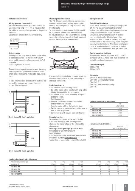
Installation instructions<br />
Wiring type and cross section<br />
Stranded wire or solid wire up to 2.5 mm 2 may be<br />
used <strong>for</strong> wiring. Strip 10–11 mm of insulation from<br />
the cables to ensure perfect operation of the push-in<br />
terminals.<br />
Use one wire <strong>for</strong> each terminal connector only.<br />
wire preparation:<br />
0.5 – 2.5 mm²<br />
10 – 11 mm<br />
Note on wiring<br />
The length of the lamp wires is limited by the value<br />
of cable capacitance. The maximum of 400 pF*<br />
would enable connection of approximately 5 m* of<br />
lamp wire.<br />
* 2 m / 160 pF <strong>for</strong> <strong>PCI</strong> 20 / 22 PRO<br />
To avoid the damage of the control gear, the wiring<br />
must be protected against short circuits to earth<br />
(sharp edged metal parts, metal cable clips, louver,<br />
etc.).<br />
In class 1 luminaires it is necessary to earth the ballast<br />
and the luminaire via the earth terminal,<br />
in class 2 luminaires not.<br />
Circuit diagram <strong>PCI</strong> class 1 application<br />
1<br />
2<br />
3<br />
4<br />
5<br />
6<br />
8<br />
1<br />
2<br />
3<br />
4<br />
5<br />
6<br />
Mounting recommendation<br />
The <strong>PCI</strong>-C has an excellent thermo management.<br />
Optimum heat transport can help improving the<br />
lifetime. Whenever possible keep the ballast away<br />
from hot parts.<br />
To ensure optimum heat removal the ECG should<br />
be mounted on a metal plate (luminaire body).<br />
No insulators between the ECG and the the cooling<br />
surface (air, adhesive tape, etc.). Finally important<br />
remains the temperature measurement.<br />
luminaire<br />
<strong>PCI</strong><br />
gap<br />
luminaire<br />
If several <strong>ballasts</strong> are installed in masts, boxes, etc.,<br />
measures must be taken to avoid overheating of<br />
individual components.<br />
Radio interference<br />
• Do not cross mains and lamp cables.<br />
• Do not lay mains cables together with lamp cables<br />
(ideally they should be 5–10 cm apart).<br />
• Do not lead mains cables too closely along the<br />
electronic ballast.<br />
• Twist lamp cables.<br />
• Increase the distance between lamp cables<br />
and earthed metal surfaces.<br />
• Keep the mains cable in the luminaire short.<br />
• Parallel runs (x) of mains and lamp cables must be<br />
kept as short as possible.<br />
• Connection to earth reduces radio interference.<br />
Important advise<br />
When a lamp is changed (at the end of its life),<br />
if a lamp is missing or after overtemperature<br />
shutdown the mains voltage of the ECG must be<br />
disconnected.<br />
Warning – starting voltage up to max. 5 kV!<br />
Not suitable <strong>for</strong> use with <strong>lamps</strong> with<br />
integral ignitors.<br />
A list of released <strong>lamps</strong> <strong>for</strong> the save operation with<br />
<strong>PCI</strong> can be found on www.tridonic.com →<br />
Techn. Data → Lamp matrix → Lamp Matrix <strong>for</strong> <strong>HI</strong>D<br />
Safety switch off<br />
End of life of the <strong>lamps</strong><br />
At the end of their useful life, <strong>lamps</strong> often cycle on/<br />
off. The <strong>PCI</strong> ballast recognises this condition<br />
and switches off the lamp, after three complete on/<br />
off cycles and whilst the supply has been<br />
unswitched. Complete lamp switch off enables<br />
easy identification of a defective lamp in the<br />
application. After a change of the faulty lamp and<br />
an interruption of the mains supply (mains reset) the<br />
ballast will strike the lamp. When there is no lamp in<br />
circuit or a defective lamp is connected to the ballast,<br />
the ballast will switch off after apr. 25 minutes.<br />
Overtemperature shutdown<br />
The units shut down at Dt approx. +12 ... +19 °C<br />
compared with tc. A mains reset must be carried out<br />
so that the units switch on again.<br />
Overload strength<br />
320 VAC / 1 h<br />
280 VAC / 10 h<br />
Standards<br />
EN 55015 (radio interference)<br />
EN 61000-3-2 (mains harmonics)<br />
EN 61347-2-12<br />
EN 61547 (interference immunity)<br />
EN 61167<br />
Harmonic distortion in the mains supply<br />
THD<br />
Type<br />
at 230 V / 50 Hz<br />
<strong>PCI</strong> 20/22 PRO < 12 %<br />
<strong>PCI</strong> 35/50 PRO < 10 %<br />
<strong>PCI</strong> 35/70 PRO < 10 %<br />
<strong>PCI</strong> 100/150 PRO < 12 %<br />
Ballast lumen factor EN 60929 8.1<br />
AC/DC-BLF<br />
Type<br />
at U = 198–254 V, 25 °C<br />
<strong>PCI</strong> 20/22 PRO 1.00<br />
<strong>PCI</strong> 35/50 PRO 1.00<br />
<strong>PCI</strong> 35/70 PRO 1.00<br />
<strong>PCI</strong> 100/150 PRO 1.00<br />
8<br />
Circuit diagram <strong>PCI</strong> class 2 application<br />
Loading of automatic circuit breakers<br />
Automatic circuit breaker type C10 C13 C16 C20 B10 B13 B16 B20<br />
Installation Ø 1.5 mm 2 1.5 mm 2 1.5 mm 2 2.5 mm 2 1.5 mm 2 1.5 mm 2 1.5 mm 2 2.5 mm 2<br />
<strong>PCI</strong> 20/22 PRO 30 40 50 60 15 20 25 30<br />
<strong>PCI</strong> 35/50 PRO 14 25 36 42 8 14 18 18<br />
<strong>PCI</strong> 35/70 PRO 14 25 36 42 8 14 18 18<br />
<strong>PCI</strong> 100/150 PRO 7 14 20 20 4 6 7 7<br />
Data sheet 04/12-835-6<br />
Subject to change without notice.<br />
www.tridonic.com 2