Electronic ballasts for high-intensity discharge lamps Indoor HI PCI ...
Electronic ballasts for high-intensity discharge lamps Indoor HI PCI ...
Electronic ballasts for high-intensity discharge lamps Indoor HI PCI ...

Create successful ePaper yourself
Turn your PDF publications into a flip-book with our unique Google optimized e-Paper software.
<strong>Electronic</strong> <strong>ballasts</strong> <strong>for</strong> <strong>high</strong>-<strong>intensity</strong> <strong>discharge</strong> <strong>lamps</strong><br />
<strong>Indoor</strong> <strong>HI</strong><br />
<strong>HI</strong><br />
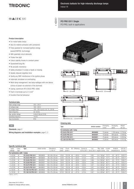
<strong>PCI</strong> PRO C011 Single<br />
<strong>PCI</strong> PRO, built-in applications<br />
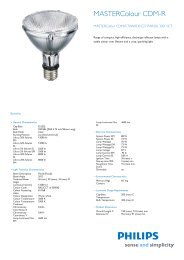
Product description<br />
• For metal halide <strong>lamps</strong><br />
• Also <strong>for</strong> mobile luminaires with connectors<br />
• Pulse packets <strong>for</strong> increased ignition energy<br />
(pulseCONTROL technology)<br />
• With patented circuit elements<br />
• Flicker-free light<br />
• Colour stability thanks to constant power<br />
• Guaranteed long life<br />
• No acoustic resonance<br />
• Safety shutdown if a lamp is faulty or missing<br />
75,5<br />
85<br />
• Greatly reduced reignition time<br />
• Hardly any EMC interference in the ignition phase<br />
25<br />
90<br />
29<br />
25<br />
100<br />
29<br />
• Automatic shutdown on overheating<br />
• Multi-lamp management: two lamp wattages with one device<br />
(choice of power via selection of the terminal)<br />
• Casing: aluminium (<strong>PCI</strong> 20/22 PRO: steel)<br />
47 – 49<br />
59<br />
63,5 – 65,5<br />
75<br />
• Push-in terminals up to 2.5 mm²<br />
78 – 80<br />
88 – 90<br />
• Excellent thermal behaviour<br />
125<br />
25<br />
29<br />
Technical data<br />
Mains voltage range<br />
220 – 240 V<br />
AC voltage range<br />
198 – 254 V<br />
DC voltage range 198 – 320 V (at 22, 50, 70, 150 W)<br />
Mains frequency<br />
50 / 60 Hz<br />
Max. ignition voltage 5 kVp (2 kVp at 22 W)<br />
Operating frequency<br />
145 Hz<br />
Type of protection<br />
IP20<br />
140<br />
128 – 130<br />
63,5 – 65,5<br />
75<br />
È<br />
Standards, page 2<br />
Wiring diagrams and installation examples, page 2, 3<br />
Ordering data<br />
Type<br />
Article number<br />
Packaging,<br />
carton<br />
Packaging,<br />
pallet<br />
Weight<br />
per pcs.<br />
For luminaires with 1 lamp<br />
<strong>PCI</strong> 20/22 PRO C011 86458600 15 pieces 1,350 pieces 0.150 kg<br />
<strong>PCI</strong> 35/50 PRO C011 86459307 15 pieces 900 pieces 0.204 kg<br />
<strong>PCI</strong> 35/70 PRO C011 86458601 15 pieces 900 pieces 0.204 kg<br />
<strong>PCI</strong> 100/150 PRO C011 86458602 15 pieces 900 pieces 0.315 kg<br />
Specific technical data<br />
Lamp<br />
wattage<br />
Lamp<br />
type<br />
Type Article number Dimensions<br />
L x W x H<br />
Lamp<br />
power<br />
Circuit<br />
power1<br />
EEI Efficiency Current at<br />
50 Hz 230 V<br />
λ at<br />
50 Hz 230 V<br />
Max. cable tc point<br />
length to lamp max.<br />
Ambient<br />
temperature ta<br />
tc/ta <strong>for</strong> ≥<br />
50,000 h<br />
For luminaires with 1 lamp<br />
1 x 20 W <strong>HI</strong> <strong>PCI</strong> 20/22 PRO C011 86458600 90 x 59 x 29 mm 20 W 23.0 W A2 > 88 % 0.10 A 0.95 2 m / 160 pF 75 °C -25 ... 60 °C 70/55 °C<br />
1 x 22 W <strong>HI</strong> <strong>PCI</strong> 20/22 PRO C011 86458600 90 x 59 x 29 mm 22 W 25.5 W A2 > 88 % 0.10 A 0.95 2 m / 160 pF 75 °C -25 ... 60 °C 70/55 °C<br />
1 x 35 W <strong>HI</strong> <strong>PCI</strong> 35/50 PRO C011 86459307 100 x 75 x 29 mm 39 W 43.5 W A2 > 89 % 0.20 A 0.96 5 m / 400 pF 80 °C -25 ... 70 °C 70/60 °C<br />
1 x 50 W <strong>HI</strong> <strong>PCI</strong> 35/50 PRO C011 86459307 100 x 75 x 29 mm 50 W 55.0 W A2 > 90 % 0.25 A 0.96 5 m / 400 pF 80 °C -25 ... 65 °C 70/55 °C<br />
1 x 35 W <strong>HI</strong> <strong>PCI</strong> 35/70 PRO C011 86458601 100 x 75 x 29 mm 39 W 43.5 W A2 > 89 % 0.20 A 0.97 5 m / 400 pF 80 °C -25 ... 70 °C 70/60 °C<br />
1 x 70 W <strong>HI</strong> <strong>PCI</strong> 35/70 PRO C011 86458601 100 x 75 x 29 mm 73 W 79.0 W A2 > 90 % 0.35 A 0.97 5 m / 400 pF 80 °C -25 ... 60 °C 70/50 °C<br />
1 x 100 W <strong>HI</strong> <strong>PCI</strong> 100/150 PRO C011 86458602 140 x 75 x 29 mm 100 W 108.0 W A2 > 91 % 0.50 A 0.97 5 m / 400 pF 85 °C -25 ... 65 °C 80/60 °C<br />
1 x 150 W <strong>HI</strong> <strong>PCI</strong> 100/150 PRO C011 86458602 140 x 75 x 29 mm 147 W 158.5 W A2 > 91 % 0.70 A 0.97 5 m / 400 pF 80 °C -25 ... 55 °C 75/50 °C<br />
1 At ta = 25 °C.<br />
Data sheet 04/12-835-6<br />
Subject to change without notice.<br />
www.tridonic.com 1
<strong>Electronic</strong> <strong>ballasts</strong> <strong>for</strong> <strong>high</strong>-<strong>intensity</strong> <strong>discharge</strong> <strong>lamps</strong><br />
<strong>Indoor</strong> <strong>HI</strong><br />
Installation instructions<br />
Wiring type and cross section<br />
Stranded wire or solid wire up to 2.5 mm 2 may be<br />
used <strong>for</strong> wiring. Strip 10–11 mm of insulation from<br />
the cables to ensure perfect operation of the push-in<br />
terminals.<br />
Use one wire <strong>for</strong> each terminal connector only.<br />
wire preparation:<br />
0.5 – 2.5 mm²<br />
10 – 11 mm<br />
Note on wiring<br />
The length of the lamp wires is limited by the value<br />
of cable capacitance. The maximum of 400 pF*<br />
would enable connection of approximately 5 m* of<br />
lamp wire.<br />
* 2 m / 160 pF <strong>for</strong> <strong>PCI</strong> 20 / 22 PRO<br />
To avoid the damage of the control gear, the wiring<br />
must be protected against short circuits to earth<br />
(sharp edged metal parts, metal cable clips, louver,<br />
etc.).<br />
In class 1 luminaires it is necessary to earth the ballast<br />
and the luminaire via the earth terminal,<br />
in class 2 luminaires not.<br />
Circuit diagram <strong>PCI</strong> class 1 application<br />
1<br />
2<br />
3<br />
4<br />
5<br />
6<br />
8<br />
1<br />
2<br />
3<br />
4<br />
5<br />
6<br />
Mounting recommendation<br />
The <strong>PCI</strong>-C has an excellent thermo management.<br />
Optimum heat transport can help improving the<br />
lifetime. Whenever possible keep the ballast away<br />
from hot parts.<br />
To ensure optimum heat removal the ECG should<br />
be mounted on a metal plate (luminaire body).<br />
No insulators between the ECG and the the cooling<br />
surface (air, adhesive tape, etc.). Finally important<br />
remains the temperature measurement.<br />
luminaire<br />
<strong>PCI</strong><br />
gap<br />
luminaire<br />
If several <strong>ballasts</strong> are installed in masts, boxes, etc.,<br />
measures must be taken to avoid overheating of<br />
individual components.<br />
Radio interference<br />
• Do not cross mains and lamp cables.<br />
• Do not lay mains cables together with lamp cables<br />
(ideally they should be 5–10 cm apart).<br />
• Do not lead mains cables too closely along the<br />
electronic ballast.<br />
• Twist lamp cables.<br />
• Increase the distance between lamp cables<br />
and earthed metal surfaces.<br />
• Keep the mains cable in the luminaire short.<br />
• Parallel runs (x) of mains and lamp cables must be<br />
kept as short as possible.<br />
• Connection to earth reduces radio interference.<br />
Important advise<br />
When a lamp is changed (at the end of its life),<br />
if a lamp is missing or after overtemperature<br />
shutdown the mains voltage of the ECG must be<br />
disconnected.<br />
Warning – starting voltage up to max. 5 kV!<br />
Not suitable <strong>for</strong> use with <strong>lamps</strong> with<br />
integral ignitors.<br />
A list of released <strong>lamps</strong> <strong>for</strong> the save operation with<br />
<strong>PCI</strong> can be found on www.tridonic.com →<br />
Techn. Data → Lamp matrix → Lamp Matrix <strong>for</strong> <strong>HI</strong>D<br />
Safety switch off<br />
End of life of the <strong>lamps</strong><br />
At the end of their useful life, <strong>lamps</strong> often cycle on/<br />
off. The <strong>PCI</strong> ballast recognises this condition<br />
and switches off the lamp, after three complete on/<br />
off cycles and whilst the supply has been<br />
unswitched. Complete lamp switch off enables<br />
easy identification of a defective lamp in the<br />
application. After a change of the faulty lamp and<br />
an interruption of the mains supply (mains reset) the<br />
ballast will strike the lamp. When there is no lamp in<br />
circuit or a defective lamp is connected to the ballast,<br />
the ballast will switch off after apr. 25 minutes.<br />
Overtemperature shutdown<br />
The units shut down at Dt approx. +12 ... +19 °C<br />
compared with tc. A mains reset must be carried out<br />
so that the units switch on again.<br />
Overload strength<br />
320 VAC / 1 h<br />
280 VAC / 10 h<br />
Standards<br />
EN 55015 (radio interference)<br />
EN 61000-3-2 (mains harmonics)<br />
EN 61347-2-12<br />
EN 61547 (interference immunity)<br />
EN 61167<br />
Harmonic distortion in the mains supply<br />
THD<br />
Type<br />
at 230 V / 50 Hz<br />
<strong>PCI</strong> 20/22 PRO < 12 %<br />
<strong>PCI</strong> 35/50 PRO < 10 %<br />
<strong>PCI</strong> 35/70 PRO < 10 %<br />
<strong>PCI</strong> 100/150 PRO < 12 %<br />
Ballast lumen factor EN 60929 8.1<br />
AC/DC-BLF<br />
Type<br />
at U = 198–254 V, 25 °C<br />
<strong>PCI</strong> 20/22 PRO 1.00<br />
<strong>PCI</strong> 35/50 PRO 1.00<br />
<strong>PCI</strong> 35/70 PRO 1.00<br />
<strong>PCI</strong> 100/150 PRO 1.00<br />
8<br />
Circuit diagram <strong>PCI</strong> class 2 application<br />
Loading of automatic circuit breakers<br />
Automatic circuit breaker type C10 C13 C16 C20 B10 B13 B16 B20<br />
Installation Ø 1.5 mm 2 1.5 mm 2 1.5 mm 2 2.5 mm 2 1.5 mm 2 1.5 mm 2 1.5 mm 2 2.5 mm 2<br />
<strong>PCI</strong> 20/22 PRO 30 40 50 60 15 20 25 30<br />
<strong>PCI</strong> 35/50 PRO 14 25 36 42 8 14 18 18<br />
<strong>PCI</strong> 35/70 PRO 14 25 36 42 8 14 18 18<br />
<strong>PCI</strong> 100/150 PRO 7 14 20 20 4 6 7 7<br />
Data sheet 04/12-835-6<br />
Subject to change without notice.<br />
www.tridonic.com 2
<strong>Electronic</strong> <strong>ballasts</strong> <strong>for</strong> <strong>high</strong>-<strong>intensity</strong> <strong>discharge</strong> <strong>lamps</strong><br />
<strong>Indoor</strong> <strong>HI</strong><br />
Multi wattage power selection<br />
The <strong>PCI</strong> PRO C011 are able to operate two different wattages. As a result of the<br />
lamp characteristics an automatic detection is not possible. The wattage selection<br />
is done via mains terminals. For using the lower power lamp connect the<br />
mains on the terminals [1] and [3]. For using the <strong>high</strong>er power lamp connect the<br />
mains on the terminals [2] and [3]. Do not connect the mains on the terminals<br />
[1] and [2] as this would destroy the device!<br />
To avoid the use of a wrong lamp we recommend to mark the luminaire with the<br />
correct lamp type.<br />
The unused multi wattage terminal [1] or [2] can lead mains voltage.<br />
Correct mains setup<br />
It is important to run the ballast only with the lamp set at the mains terminals.<br />
Over powering of the lamp will lead to a shorter lifetime or destruction of the<br />
lamp. Under powering may lead to an early shutdown or colour shifts in the lamp<br />
as well as a shorter life time.<br />
Note on <strong>PCI</strong> 20 / 22 PRO C011<br />
L<br />
N<br />
Pe<br />
x<br />
max. 5 kV<br />
20 W<br />
35 W<br />
100 W<br />
Circuit diagram multiwatt <strong>for</strong> 20, 35 and 100 W<br />
L<br />
N<br />
Pe<br />
1<br />
2<br />
3<br />
4<br />
5<br />
6<br />
8<br />
That ballast is designed to drive a standard 20 W lamp as well as 22 W <strong>lamps</strong>*.<br />
In this setup 20 W <strong>lamps</strong> cannot be ignited.<br />
* Philips CDM-TM 20<br />
x<br />
max. 5 kV<br />
1<br />
2<br />
3<br />
4<br />
5<br />
6<br />
8<br />
22 W<br />
50 W<br />
70 W<br />
150 W<br />
Circuit diagram multiwatt <strong>for</strong> 22, 50, 70 and 150 W<br />
Temperature range<br />
The ta temperature value is the basis <strong>for</strong> specifying<br />
the rated life.<br />
The relationship between the tc temperature and<br />
the ta temperature depends on the design of the<br />
luminaire. If the measured tc temperature is approximately<br />
5 K under the tc max. temperature the ta<br />
temperature should be checked and, if necessary,<br />
measurements should be taken on the critical components<br />
(e.g. electrolytic capacitor).<br />
Detailed in<strong>for</strong>mation is available on request.<br />
<strong>PCI</strong> PRO C011 is designed <strong>for</strong> an average life of<br />
50,000 hours under rated conditions, with a failure<br />
probability of less than 10 %. This corresponds to<br />
an average failure rate of 0.2 % per 1,000 hours of<br />
operation.<br />
The specified tc temperature is the maximum permitted<br />
value (rated temperature according to EN<br />
61347 -1). Above this safety-related value the thermal<br />
cutout protects the device against damage.<br />
The expected lifetime values are shown in the<br />
following table. The tc values are the relevant values<br />
here.<br />
Data sheet 04/12-835-6<br />
Subject to change without notice.<br />
www.tridonic.com 3
<strong>Electronic</strong> <strong>ballasts</strong> <strong>for</strong> <strong>high</strong>-<strong>intensity</strong> <strong>discharge</strong> <strong>lamps</strong><br />
<strong>Indoor</strong> <strong>HI</strong><br />
Expected lifetime<br />
Type Lamp type Lamp power ta 45 °C 50 °C 55 °C 60 °C 65 °C 70 °C<br />
<strong>HI</strong><br />
<strong>PCI</strong> 20/22 PRO<br />
<strong>HI</strong><br />
<strong>HI</strong><br />
<strong>PCI</strong> 35/50 PRO<br />
<strong>HI</strong><br />
<strong>HI</strong><br />
<strong>PCI</strong> 35/70 PRO<br />
<strong>HI</strong><br />
<strong>HI</strong><br />
<strong>PCI</strong> 100/150 PRO<br />
<strong>HI</strong><br />
x ... not permitted<br />
1x20 W<br />
1x22 W<br />
1x35 W<br />
1x50 W<br />
1x35 W<br />
1x70 W<br />
1x100 W<br />
1x150 W<br />
tc 60 °C 65 °C 70 °C 75 °C x x<br />
Lifetime > 75,000 h 75,000 h 55,000 h 40,000 h x x<br />
tc 60 °C 65 °C 70 °C 75 °C x x<br />
Lifetime > 75,000 h 75,000 h 55,000 h 40,000 h x x<br />
tc 55 °C 60 °C 65 °C 70 °C 75 °C 80 °C<br />
Lifetime > 55,000 h > 55,000 h > 55,000 h 55,000 h 40,000 h 25,000 h<br />
tc 60 °C 65 °C 70 °C 75 °C 80 °C x<br />
Lifetime > 55,000 h > 55,000 h 55,000 h 40,000 h 25,000 h x<br />
tc 55 °C 60 °C 65 °C 70 °C 75 °C 80 °C<br />
Lifetime > 55,000 h > 55,000 h > 55,000 h 55,000 h 40,000 h 25,000 h<br />
tc 65 °C 70 °C 75 °C 80 °C x x<br />
Lifetime > 55,000 h 55,000 h 40,000 h 25,000 h x x<br />
tc 65 °C 70 °C 75 °C 80 °C 85 °C x<br />
Lifetime > 70,000 h > 70,000 h 70,000 h 50,000 h 35,000 h x<br />
tc 70 °C 75 °C 80 °C x x x<br />
Lifetime 70,000 h 50,000 h 35,000 h x x x<br />
Storage conditions<br />
Humidity: 5 % up to max. 85 %,<br />
not condensed<br />
(max. 56 days/year at 85 %)<br />
Storage temperature: -40 °C up to max. +80 °C<br />
The devices have to be within the specified temperature range (ta) be<strong>for</strong>e they<br />
can be operated.<br />
Isolation and electric strength testing of luminaires<br />
<strong>Electronic</strong> devices can be damaged by <strong>high</strong> voltage. This has to be considered<br />
during the routine testing of the luminaires in production.<br />
According to IEC 60598-1 Annex Q (in<strong>for</strong>mative only!) or ENEC 303-Annex A, each<br />
luminaire should be submitted to an isolation test with 500 V DC <strong>for</strong> 1 second. This<br />
test voltage should be connected between the interconnected phase and neutral<br />
terminals and the earth terminal.<br />
The isolation resistance must be at least 2 MΩ.<br />
As an alternative, IEC 60598-1 Annex Q describes a test of the electrical strength<br />
with 1500 V AC (or 1.414 x 1500 V DC). To avoid damage to the electronic devices this<br />
test must not be conducted.<br />
Additional in<strong>for</strong>mation<br />
Additional technical in<strong>for</strong>mation at<br />
www.tridonic.com → Technical Data<br />
Guarantee conditions at<br />
www.tridonic.com → Services<br />
No warranty if device was opened.<br />
Data sheet 04/12-835-6<br />
Subject to change without notice.<br />
www.tridonic.com 4