Introduction to ARIX CNC milling machine
Introduction to ARIX CNC milling machine
Introduction to ARIX CNC milling machine

You also want an ePaper? Increase the reach of your titles
YUMPU automatically turns print PDFs into web optimized ePapers that Google loves.
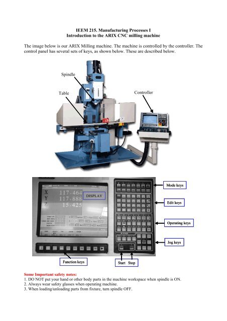
IEEM 215. Manufacturing Processes I<br />
<strong>Introduction</strong> <strong>to</strong> the <strong>ARIX</strong> <strong>CNC</strong> <strong>milling</strong> <strong>machine</strong><br />
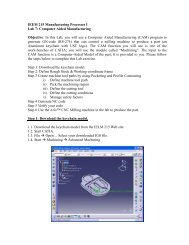
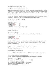
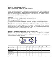
The image below is our <strong>ARIX</strong> Milling <strong>machine</strong>. The <strong>machine</strong> is controlled by the controller. The<br />
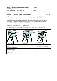
control panel has several sets of keys, as shown below. These are described below.<br />
Spindle<br />
Table<br />
Controller<br />
Mode keys<br />
DISPLAY<br />
Edit keys<br />
Operating keys<br />
Jog keys<br />
Function keys<br />
Start S<strong>to</strong>p<br />
Some Important safety notes:<br />
1. DO NOT put your hand or other body parts in the <strong>machine</strong> workspace when spindle is ON.<br />
2. Always wear safety glasses when operating <strong>machine</strong>.<br />
3. When loading/unloading parts from fixture, turn spindle OFF.
Explanation of mode and Function keys<br />
Manual: To execute home, coordinate selection, setup, go and timer function.<br />
Teach in: Perform the pattern drilling, pocket mill, facing, frame mill.<br />
Program: To edit, manage and simulate the programs, files transfer.<br />
Run: To perform au<strong>to</strong>matic operation.<br />
Cam: Defines pocket shapes for au<strong>to</strong> programming [we will not use this mode].<br />
System: Check and set system parameters.<br />
Screen off: To turn the display moni<strong>to</strong>r ON/OFF. Leave this On at all times.<br />
Function keys: F1-F8 are for sub-functions under each mode operation<br />
Explanation of the standard operation keys<br />
Lamp Switch: Turn on/off the lamp.<br />
Coolant switch: Turn on/off the coolant pump.<br />
CCW Spindle: Turn on the spindle in counter clockwise direction.<br />
S<strong>to</strong>p: Turn off the spindle.<br />
CW Spindle: Turn on the spindle in clockwise direction.<br />
Jog Enable: Enable jog keys for movement of X, Y, Z axes. Each “jog” motion is a short step<br />
motion of that axis, at the current feed rate; Jog speed will turn <strong>to</strong> G00 after the RAPID key is<br />
pressed.
Cycle Start: Start the cycles / program.<br />
S<strong>to</strong>p: S<strong>to</strong>p the cycles / program.<br />
Rapid Enable: Enable the jog speed change <strong>to</strong> G00 from feed speed.<br />
How <strong>to</strong> use the <strong>machine</strong><br />
1. Manual mode operation<br />
• Make sure the part is fixed securely in fixture.<br />
• Make sure the <strong>to</strong>ol is fixed securely in the <strong>to</strong>ol holder, and <strong>to</strong>ol holder is secure on<br />
spindle.<br />
• Know the feed rate and spindle speed you will use before starting the <strong>machine</strong>.<br />
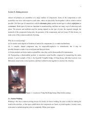
Emergency<br />
s<strong>to</strong>p<br />
Servomo<strong>to</strong>r OFF, ON<br />
Joystick: moves X- and Y in + and - directions<br />
Z+: move table up<br />
Z-: move table down<br />
Adjust feed rate Adjust rapid jog speed Adjust Spindle speed<br />
(i) Power ON the <strong>machine</strong>.<br />
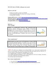
(ii) Select Manual mode key, <strong>to</strong> get the following screen display:
(iii) Turn Servo On and press F1/ Home function key and then press Cycle Start <strong>to</strong> execute<br />
home process.<br />
(iv) Press Work table up/down Z+ / Z- but<strong>to</strong>ns <strong>to</strong> adjust working level below Z axis<br />
(v) Adjust the feed speed adjust knob <strong>to</strong> desired value.<br />
(vi) Set the <strong>machine</strong> coordinates with respect <strong>to</strong> the part. It is common <strong>to</strong> use three planar faces<br />
of the part <strong>to</strong> set the XY, YZ and XZ planes. To set the X-coordinate of the <strong>machine</strong> coordinate<br />
frame, move the <strong>to</strong>ol till it just <strong>to</strong>uches the plane you want <strong>to</strong> call the YZ plane on the s<strong>to</strong>ck.<br />
Manual table movement can be done by four different ways:<br />
(a) Press the Jog Enable key, use the joystick for X-, Y- and Z- movements.<br />
(b) You can also move the table directly by pressing the jog keys for X- Y- and Z axes.<br />
(c) For very fine stepping, use the encoder<br />
Encoder<br />
Axis select<br />
Speed select<br />
(d) Directly input the coordinates and spindle RPM using F3 / MDI (manual data input).<br />
If your NC program has its axis origin at a corner of the workpiece, then set the Part work<br />
coordinates (work zeros) set up by pressing F4 / SETUP.<br />
If the coordinates need <strong>to</strong> be set <strong>to</strong> some other values, Select Work Coordinate by pressing F2 /<br />
WCS, and then set the coordinate values for X- Y- and Z-.
Running a program<br />
Import a program file<br />
1. Select Program mode by pressing Program key.<br />
2. Select F1 / File manage.<br />
3. Select F4 / Import <strong>to</strong> insert file.<br />
4. Select file path from B:\*.* of floppy drive or from [ N ] network by using page up / down<br />
and ↑ ↓ edit keys and confirm by ‹→›.<br />
5. Press F1 / OK <strong>to</strong> input the selected file.<br />
Work coordinates setup<br />
1. Place and fix the part in the clamp on the worktable.<br />
2. Change <strong>to</strong>ol <strong>to</strong> the desired end mill if necessary.<br />
3. Adjust the part <strong>to</strong> a proper Z level below the <strong>to</strong>ol by using worktable adjust but<strong>to</strong>ns Z+ / Z-<br />
on control panel.<br />
4. Select Manual mode.<br />
5. Select F2 / Select WCS and F2 again for G54 coordinate system.<br />
6. Go back by pressing ◄ key and select F4 / Setup.<br />
7. Jog the part <strong>to</strong> approach the <strong>to</strong>ol by using jog keys and joystick.<br />
8. Fine adjust <strong>to</strong> enable the part just in <strong>to</strong>uch the <strong>to</strong>ol by using the hand held encoder for X<br />
axis.<br />
9. Select F2 / Set X.<br />
10. Press ◄ <strong>to</strong> go back, select F2 / Select WCS and using ↓ ↑ edit keys <strong>to</strong> highlight X axis.<br />
11. Press F1 / Data input.<br />
12. Input the new calculated <strong>to</strong>ol radius compensated value, then confirmed by ‹→›.<br />
13. Press ◄ <strong>to</strong> go back and repeat steps 6-12 for Y axis.<br />
14. For safety purpose in test run, adjust Z axis so that the <strong>to</strong>ol is kept in a clearance level<br />
above the part then select F4 / Set Z.<br />
Simulate and run a program file<br />
1. Select Run mode and turn Servo On.<br />
2. Press F1 / Select work file.<br />
3. Select the file by using page up / down and ↑ ↓ edit keys, then confirm by ‹→›.<br />
4. Press F5 for Graphical simulation: the <strong>to</strong>ol path will be plotted on the CRT.<br />
5. If there is no error visible, press Cycle start for a test run, check if the <strong>to</strong>ol path is within<br />
the desired working area in the first few steps.<br />
6. Press Cycle s<strong>to</strong>p and red Reset edit key.<br />
7. Go back <strong>to</strong> Manual mode and press F4 / Setup again.<br />
8. Jog and fine adjust the <strong>to</strong>ol just in <strong>to</strong>uch the part in Z axis and press F4 / Set Z for Z work<br />
zero.<br />
9. Raise up the <strong>to</strong>ol and go back <strong>to</strong> Run mode.<br />
10. Turn on Compressed air (for cutting plastic) and Coolant (for cutting metal) if necessary.<br />
11. Press F5 for simulation and then Cycle start <strong>to</strong> run the program au<strong>to</strong>matically.