IEEM 215 Manufacturing Processes I Lab 7: Computer Aided ...
IEEM 215 Manufacturing Processes I Lab 7: Computer Aided ...
IEEM 215 Manufacturing Processes I Lab 7: Computer Aided ...

Create successful ePaper yourself
Turn your PDF publications into a flip-book with our unique Google optimized e-Paper software.
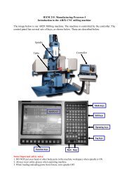
<strong>IEEM</strong> <strong>215</strong> <strong>Manufacturing</strong> <strong>Processes</strong> I<strong>Lab</strong> 7: <strong>Computer</strong> <strong>Aided</strong> <strong>Manufacturing</strong>Objective: In this <strong>Lab</strong>, you will use a <strong>Computer</strong> <strong>Aided</strong> <strong>Manufacturing</strong> (CAM) program togenerate GN-code (RS-274) that can control a milling machine to produce a part (anAluminum keychain with UST logo). The CAM function you will use is one of thework-benches of CATIA; you will use the module called “Machining”. The input to theCAM function is a <strong>Computer</strong>-<strong>Aided</strong> Model of the part; it is provided to you. Please followthe steps below to complete this <strong>Lab</strong> exercise.Step 1: Download the keychain model.Step 2: Define Rough Stock & Working coordinate frameStep 3 Create machine tool paths by using Pocketing and Profile Contouringi) Define machine tool pathii) Pick the machining regioniii) Define the cutting tooliv) Define the cutting conditionsv) Manage safety factorsStep 4 Generate NC codeStep 5 Verify your codeStep 6 Use the Arix CNC Milling machine in the lab to produce the part.Step 1: Download the keychain model.1.1. Download the keychain model from the IELM <strong>215</strong> Web site1.2. Start CATIA.1.3. File Open… Select your downloaded IGS file.1.4. Start Machining Advanced Machining
Step 2: Define Rough Stock & Working coordinate film2.1 Define Rough Stock:Click rough stock , select the model in both, Destination box and Part body box. Inputthe parameters as below.Note: Rough Stock is the initial material that will be machined. A 60mm x 50mm x 3.5mmaluminum plate is provided to you as a rough stock.2.2 Define working coordinate frame:Double-Click “Default reference machining axis for part Operation.1” (The green coordinateframe) on the screen. Click the origin (red dot) in the dialog box. Select the Left corner pointof the top face of the rough stock as shown as the following figures.Note: You must use the same coordinate frame when you setup the part on the CNC machine.
Default reference machining axis for part Operation.1Step 3 Create machining tool paths by using Pocketing and Profile Contouring3.1 Pocketing:From the CATIA menus, Insert Machining operations Prismatic Machining operations PocketingComplete the specifications in the five main categories to finish the pocketing, as below.i) Define machining tool path.1.) Select the Radial Tab, Select Stepover ratio from Mode.2.) Set Percentage of tool diameter to 30.3.) Set Overhang: to 30.4.) Select the Axial Tab, Select Maximum depth of cut, set its value as 0.3mm5.) Select the Finishing Tab6.) Select Side finish last level from Mode; set value the of “Side finish thickness” =0.3mm
Note: Stepover ratio is the percentage of tool diameter engaged with the material.Note: Maximum depth of cut and Stepover ratio are directly proportional to the total contactarea between cutting tool and the material.ii) Pick the machining region.1.) Pick the top plane of the rough stock as top plane.2.) Pick the bottom plane of any pocket as bottom.Hints: You can press up/down buttons to select the hided region.iii) Define cutting tool.You will use a 3mm Diameter flat end mill to do the pocketing.1.) Set the tool Diameter (D) to 3mm.2.) Set the Corner Radius (Rc) to 0mm since we are using flat end mill.iv) Define cutting conditions
Input the parameters as shown in the figure below.v) Manage safety factors.You will set the methods for tool approaching and retraction here. The distance of clearancemust be specified as well.1.) Select Approach from the Macro Management2.) Choose Ramping in Mode and set the vertical safety distance to 3mm.3.) Select Retract from the Macro Management4.) Choose Axial in Mode, and change the value to 3mm.5.) Select Clearance from the Macro Management6.) Choose Distance in Mode, and change the values to 3mm
7.) Activate Approach, Retract and Clearance (mouse: Right-Click).Note: Approach motion ensures the machine tool does not plunge straight down into thematerial. Retraction and Clearance ensure that the tool does not hit any uncut region whenjumping from one pocket to another.3.2 Repeat step 3.1 by selecting the rest of pocket regions (Totally five pockets) in ii).To check the tool paths you have been made, you can select them in the tree andRight-Click Selected objects Replay tool path. You should be able to see theTool paths.
3.3 Profile ContouringFrom the menus, Insert Machining operations Prismatic Machining operations Profile ContouringInput the same parameter values as for pocketing in i), iii), iv), v), including stepover values,Maximum depth of cut, cutting tool values, Feedrates and Spindle Speed, etc.ii) Pick the machining region.1.) Pick the top plane of the rough stock as top plane.2.) Pick the bottom plane of the rough stock as bottom.3.) Set offset on bottom to 0.2mmSelect all the pocketing and the Profile Contouring from the feature tree. By using:Right-Click selected object Tool Path Replay, you can simulate the tool path that youhave generated.
Click OK to stop.Step 4 Generate NC codeTo generate NC code, you have to select a Post Processor (pp) to translate the machiningmotion commands (in a language called APT) into NC code. Post Processor programs areprovided by the milling machine vendor, since different machines use different motioncontrollers. In this <strong>Lab</strong>, we will use a Post Processor call “Fanuc”.1.) Tools Options Machining, select Output tab, select “IMS_” from Post Processor andclick OK to close the dialog box.2.) Right-Click to the <strong>Manufacturing</strong> Program.1 from the tree, Move to <strong>Manufacturing</strong>Program.1 object Generate NC code interactively. Select “fancu0” as the Post Processorfrom the NC Code Tab. Setup the output format and file path as follows:3.) Click Execute.
Step 5 Verify your codeOpen your NC code and check carefully that all the initial setting and the ending are correct.You can use the document of RS-274 as reference.Please check the code with your TA to ensure the code could use to machine.Step 6 Produce your UST souvenirSince we have only one CNC machine, each group must machine their part at different timeslots. The total time to learn the basics of the CNC Machine is approximately 30 min, and thetime to machine the part is also approximately 30 min. Please book a convenient time withyour TA to complete the machining.<strong>Lab</strong> notes prepared by Fan Sai Kit for IELM <strong>215</strong>, IELM, HKUST.