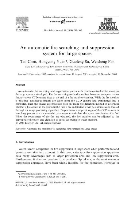
An automatic fire searching and suppression system for large spaces
An automatic fire searching and suppression system for large spaces
An automatic fire searching and suppression system for large spaces

You also want an ePaper? Increase the reach of your titles
YUMPU automatically turns print PDFs into web optimized ePapers that Google loves.
ARTICLE IN PRESS<br />
Fire Safety Journal 39 (2004) 297–307<br />
<strong>An</strong> <strong>automatic</strong> <strong>fire</strong> <strong>searching</strong> <strong>and</strong> <strong>suppression</strong><br />
<strong>system</strong> <strong>for</strong> <strong>large</strong> <strong>spaces</strong><br />
Tao Chen, Hongyong Yuan*, Guofeng Su, Weicheng Fan<br />
State Key Laboratory of Fire Science, University of Science <strong>and</strong> Technology of China,<br />
Hefei 230027, PR China<br />
Received 25 November 2002; received in revised <strong>for</strong>m 11 August 2003; accepted 19 November 2003<br />
Abstract<br />
<strong>An</strong> <strong>automatic</strong> <strong>fire</strong> <strong>searching</strong> <strong>and</strong> <strong>suppression</strong> <strong>system</strong> with remote-controlled <strong>fire</strong> monitors<br />
<strong>for</strong> <strong>large</strong> <strong>spaces</strong> is developed. The <strong>fire</strong> <strong>searching</strong> method is realized based on computer vision<br />
theory via one CCD camera fixed at the end of a <strong>fire</strong> monitor chamber. While the <strong>fire</strong> monitor<br />
is pivoting, continuous images are taken from the CCD camera <strong>and</strong> transmitted into a<br />
computer. Then the images are processed with an image <strong>fire</strong> detection method to determine<br />
whether a <strong>fire</strong> occurs in the vision field. Once a <strong>fire</strong> is detected, it will be <strong>automatic</strong>ally located<br />
through an image processing algorithm. Displacement <strong>and</strong> pivot angle of the CCD camera in<br />
<strong>searching</strong> process are the essential parameters to calculate the space coordinates of a <strong>fire</strong>.<br />
When the coordinates of the <strong>fire</strong> are obtained, the <strong>fire</strong> monitor can be adjusted to the<br />
appropriate direction <strong>and</strong> elevation to spray according to water pressure.<br />
r 2003 Elsevier Ltd. All rights reserved.<br />
Keywords: Automatic <strong>fire</strong> monitor; Fire <strong>searching</strong>; Fire <strong>suppression</strong>; Large <strong>spaces</strong><br />
1. Introduction<br />
Water is most acceptable <strong>for</strong> <strong>fire</strong> <strong>suppression</strong> in <strong>large</strong> space when per<strong>for</strong>mance <strong>and</strong><br />
quantity are taken into account. In this case, water type <strong>fire</strong> <strong>suppression</strong> apparatus<br />
have many advantages such as <strong>large</strong>r protection area <strong>and</strong> low <strong>suppression</strong> cost.<br />
Furthermore, it does not produce toxic products. Sprinklers, as the most common<br />
<strong>suppression</strong> apparatus, have been widely installed <strong>for</strong> <strong>fire</strong> protection. However in<br />
*Corresponding author. Fax: +86-551-3606430.<br />
E-mail address: yuanhy@ustc.edu.cn (H. Yuan).<br />
0379-7112/$ - see front matter r 2003 Elsevier Ltd. All rights reserved.<br />
doi:10.1016/j.<strong>fire</strong>saf.2003.11.007
ARTICLE IN PRESS<br />
298<br />
T. Chen et al. / Fire Safety Journal 39 (2004) 297–307<br />
Nomenclature<br />
D chamber length of the <strong>fire</strong> monitor<br />
d measured distance between a <strong>fire</strong> <strong>and</strong> the pivot point of the <strong>fire</strong> monitor<br />
d c calculated distance between a <strong>fire</strong> <strong>and</strong> the pivot point of the <strong>fire</strong> monitor<br />
f focal length of the CCD camera<br />
e distance between a <strong>fire</strong> <strong>and</strong> the shooting spot of the <strong>fire</strong> monitor<br />
(i 1 , j 1 ) pixel coordinates of a <strong>fire</strong> in the image at time t 1<br />
(i 2 , j 2 ) pixel coordinates of a <strong>fire</strong> in the image at time t 2<br />
H maximum pixel number per row of the CCD<br />
h actual width of the CCD<br />
T time of extinguish after the water is issued<br />
T s time of <strong>searching</strong> process<br />
V maximum pixel number per column of the CCD<br />
v actual height of the CCD<br />
X–Y–Z fixed object space coordinate <strong>system</strong><br />
X 1 –Y 1 –Z 1 camera coordinate <strong>system</strong> at time t 1<br />
X 2 –Y 2 –Z 2 camera coordinate <strong>system</strong> at time t 2<br />
(X,Y,Z) coordinates in X-Y-Z coordinate <strong>system</strong><br />
(X 1 ,Y 1 ,Z 1 ) coordinates in X 1 -Y 1 -Z 1 coordinate <strong>system</strong><br />
(X 2 ,Y 2 ,Z 2 ) coordinates in X 2 -Y 2 -Z 2 coordinate <strong>system</strong><br />
x–y image plane of the camera<br />
(x,y) coordinates in x–y image plane<br />
(x 1 ,y 1 ) coordinates in image plane at time t 1<br />
(x 2 ,y 2 ) coordinates in image plane at time t 2<br />
a angle to Z-axis in Y–Z plane of the <strong>fire</strong> spot<br />
b visual angle of the CCD camera<br />
o 1 angle to Z-axis in Y–Z plane of Z 1 -axis<br />
angle to Z-axis in Y–Z plane of Z 2 -axis<br />
o 2<br />
recent years, with the increasing <strong>large</strong> space buildings, the suitability of sprinkler use<br />
in such <strong>large</strong> space situations has been challenged.<br />
Commonly, thermally activated sprinklers are not suitable <strong>for</strong> high ceiling space<br />
use. The height of the ceiling in <strong>large</strong> space will greatly affect the sprinklers so that<br />
they cannot provide effective protection. The main problem is the activation delays<br />
of the sprinklers in <strong>large</strong> <strong>spaces</strong>, particularly high ceiling <strong>spaces</strong>. For example, even a<br />
5 MW <strong>fire</strong> on the atrium floor would not generate a smoke temperature high enough<br />
to activate the sprinklers on an atrium ceiling higher than 15 m [1, 2]. Due to the<br />
distance between the potential <strong>fire</strong> source <strong>and</strong> the sprinkler heads which are mounted<br />
near the ceiling, sprinkler activation may be too late to minimize the <strong>fire</strong> hazards or<br />
damage. Even the early <strong>suppression</strong> fast response (ESFR) sprinklers have the<br />
recommended height limit [3–5]. Moreover, the height may also affect how<br />
much water can reach the flame be<strong>for</strong>e vaporized or blown away by the <strong>fire</strong><br />
plume [6]. In those <strong>large</strong> <strong>spaces</strong> where the combustible materials are distributed
ARTICLE IN PRESS<br />
T. Chen et al. / Fire Safety Journal 39 (2004) 297–307 299<br />
dispersedly, it is also not very efficient to install many sprinklers to cover all these<br />
materials.<br />
Now, robotic <strong>fire</strong> monitor that can be <strong>automatic</strong>ally controlled by computer <strong>and</strong><br />
can work as a linkage device in a <strong>fire</strong> detection <strong>and</strong> <strong>suppression</strong> <strong>system</strong> is becoming a<br />
more suitable solution. Liu et al. [7] <strong>and</strong> Yuan et al. [8] have done some early<br />
researches. Compared to a sprinkler, a <strong>fire</strong> monitor has many advantages. First, the<br />
most remarkable advantage is that the activation time of these <strong>fire</strong> monitors is much<br />
shorter than sprinklers. They are activated by the alarm signal given by the <strong>fire</strong><br />
detectors which are much more sensitive than the sprinklers’ explosion glass bulbs.<br />
These detectors can be conventional <strong>fire</strong> detectors or gas sensors. Second, water<br />
stream from a <strong>fire</strong> monitor has a higher speed, a greater flux <strong>and</strong> a <strong>large</strong>r impulse so<br />
it is more effective <strong>for</strong> <strong>fire</strong> <strong>suppression</strong>. Its spot type <strong>suppression</strong> may sometimes<br />
avoid the consequent losses caused by sprinklers <strong>and</strong> will not cause a downward<br />
moving of smoke [9] to endanger the occupants in the building. Last, a typical <strong>fire</strong><br />
monitor has a shooting range of 50 m long, which enables it to protect much <strong>large</strong>r<br />
area than a sprinkler.<br />
In this paper, a new <strong>fire</strong> <strong>searching</strong> <strong>and</strong> <strong>suppression</strong> <strong>system</strong> using such <strong>automatic</strong><br />
<strong>fire</strong> monitors is described. These <strong>fire</strong> monitors are assembled into a <strong>large</strong>r <strong>fire</strong><br />
detection–<strong>suppression</strong> <strong>system</strong>. After <strong>fire</strong> confirmation <strong>and</strong> <strong>searching</strong> process, the<br />
direction <strong>and</strong> elevation of the <strong>fire</strong> monitor can be easily calculated <strong>and</strong> <strong>suppression</strong><br />
can consequently be executed.<br />
2. Principle<br />
2.1. Structure of the <strong>automatic</strong> <strong>fire</strong> monitor <strong>system</strong><br />
The <strong>automatic</strong> <strong>fire</strong> monitor <strong>system</strong> is a <strong>fire</strong> detection–<strong>searching</strong>–<strong>suppression</strong><br />
<strong>system</strong> [10] which consists of three parts: the <strong>fire</strong> detection module (including<br />
detectors <strong>and</strong> the detector controller), the <strong>fire</strong> monitor module (including the <strong>fire</strong><br />
monitor, the <strong>fire</strong> monitor manual controller <strong>and</strong> the CCD camera) <strong>and</strong> the central<br />
control module (including the computer, data-sampling interfaces <strong>and</strong> communication<br />
interfaces). In this <strong>system</strong> (shown in Fig. 1), the <strong>fire</strong> monitor serves as a <strong>fire</strong><br />
<strong>searching</strong> <strong>and</strong> <strong>suppression</strong> device in conjunction with the <strong>fire</strong> detectors. Once the<br />
detector is in alarm state, the <strong>fire</strong> detection module will give a <strong>fire</strong> alarm signal <strong>and</strong><br />
the central control module will send a linkage signal to activate the corresponding<br />
<strong>fire</strong> monitor.<br />
The <strong>fire</strong> monitor module <strong>and</strong> the central control module accomplish the <strong>fire</strong><br />
<strong>searching</strong> <strong>and</strong> <strong>suppression</strong> after the <strong>fire</strong> monitor is activated. <strong>An</strong> <strong>automatic</strong> <strong>fire</strong><br />
monitor itself is much like a little barbette which consists of a chamber, a CCD<br />
camera, a motor, an electromagnet valve, a computer connection interface (RS485<br />
<strong>and</strong> video) <strong>and</strong> a shell. At the end of the <strong>fire</strong> monitor chamber, a CCD camera is<br />
fixed which is used <strong>for</strong> capturing the spot images. The optical axis of the CCD<br />
camera is adjusted parallel to the axis of the <strong>fire</strong> monitor chamber. In <strong>large</strong> space<br />
condition, the two axes can be practically considered coincident. The electromagnet
ARTICLE IN PRESS<br />
300<br />
T. Chen et al. / Fire Safety Journal 39 (2004) 297–307<br />
Fig. 1. Sketch of <strong>automatic</strong> <strong>fire</strong> monitor <strong>system</strong>.<br />
Table 1<br />
Technical specification of the water cannon<br />
Maximum operating pressure<br />
16 bar (16 10 5 Pa)<br />
Operating pressure<br />
8 bar (8 10 5 Pa) (lower pressure is allowable)<br />
Flow rate<br />
1200 lpm<br />
Pivot range<br />
80 ?+60 max vertical, 7100 max horizontal<br />
Pivoting speed 9 /s<br />
Remote control<br />
RS-485 bus<br />
Computer interface<br />
RS-232 (with a protocol conversion box)<br />
valve <strong>and</strong> the motor inside the <strong>fire</strong> monitor shell are controlled by the computer via<br />
RS-485 serial communication interface. The <strong>for</strong>mer releases or holds the water jet<br />
<strong>and</strong> the latter drives the <strong>fire</strong> monitor chamber to pivot in left–right <strong>and</strong> up–down<br />
directions. Furthermore, the pivot angle of the chamber is fed back to the computer<br />
as an important parameter to the <strong>fire</strong> <strong>searching</strong> algorithm.<br />
The <strong>fire</strong> monitor has dual control modes. A manual <strong>fire</strong> monitor controller is used<br />
<strong>for</strong> manual operations at emergency situation. In case a <strong>fire</strong> is discovered by a<br />
human, the cannon can be operated manually by a trained personnel. In the<br />
<strong>automatic</strong> mode, multiple <strong>fire</strong> monitors can be controlled <strong>and</strong> switches between them<br />
are available. The main technical specifications of a typical <strong>fire</strong> monitor are shown in<br />
Table 1.<br />
2.2. Fire <strong>searching</strong> method based on computer vision theory<br />
Computer vision tries to simulate man’s vision <strong>and</strong> reconstruct 3D scene with 2D<br />
images. Usually, at least two cameras are needed to construct a 3D vision <strong>system</strong><br />
[11]. Baseline distance between the two cameras is essential to reconstruct 3D<br />
coordinates. The relationshipbetween image coordinates <strong>and</strong> object coordinates
ARTICLE IN PRESS<br />
T. Chen et al. / Fire Safety Journal 39 (2004) 297–307 301<br />
based on single fixed camera imaging <strong>system</strong> can be established as<br />
x i ¼ f X o<br />
Z o<br />
;<br />
y i ¼ f Y o<br />
Z o<br />
;<br />
ð1Þ<br />
where (x i , y i ) represent the image coordinates, (X o , Y o , Z o ) represent the object<br />
coordinates <strong>and</strong> f represents the camera’s focal length.<br />
Here we use only one CCD camera to construct a vision <strong>system</strong> according to the<br />
position change of the camera between time t 1 <strong>and</strong> t 2 when it is pivoting in Y–Z<br />
plane. Fig. 2 shows the coordinates <strong>system</strong> in our vision <strong>system</strong>.<br />
* The pivoting point of the camera–<strong>fire</strong> monitor <strong>system</strong> is the origin of X–Y–Z<br />
coordinate <strong>system</strong>.<br />
* The camera’s optical center is the origin of the X 1 –Y 1 –Z 1 <strong>and</strong> X 2 –Y 2 –Z 2<br />
coordinate <strong>system</strong>s.<br />
* X–Y–Z, X 1 –Y 1 –Z 1 <strong>and</strong> X 2 –Y 2 –Z 2 are right-h<strong>and</strong>ed coordinate <strong>system</strong>s.<br />
* In X–Y–Z coordinate <strong>system</strong>, o measures zero along Z-axis <strong>and</strong> positive by righth<strong>and</strong><br />
rule with X-axis as the thumb direction. Thus we have o 1 o0 <strong>and</strong> o 2 >0.<br />
* P(d,a) in the Y–Z plane is supposed to be the <strong>fire</strong> position in object space.<br />
From Eq. (1) we have<br />
Z 1 ¼ f Y 1<br />
y 1<br />
;<br />
Z 2 ¼ f Y 2<br />
y 2<br />
:<br />
ð2Þ<br />
Between object space coordinates <strong>and</strong> image space coordinates we have<br />
Y ¼ Y 1 cos o 1 Z 1 sin o 1 þ D sin o 1 ;<br />
Z ¼ Y 1 sin o 1 þ Z 1 cos o 1 þ D cos o 1 ;<br />
ð3Þ<br />
Fig. 2. Coordinates built from computer vision theory.
ARTICLE IN PRESS<br />
302<br />
T. Chen et al. / Fire Safety Journal 39 (2004) 297–307<br />
Y ¼ Y 2 cos o 2 Z 2 sin o 2 þ D sin o 2 ;<br />
Z ¼ Y 2 sin o 2 þ Z 2 cos o 2 þ D cos o 2 :<br />
ð4Þ<br />
Take Eq. (2) into (3) <strong>and</strong> eliminate Y 1 , the relationshipbetween Y <strong>and</strong> Z has an<br />
expression<br />
Y ¼ ðy 1 cos o 1 f sin o 1 ÞðZ D cos o 1 Þ<br />
þ D sin o 1 : ð5Þ<br />
y 1 sin o 1 þ f cos o 1<br />
Take Eq. (2) into (4) <strong>and</strong> eliminate Y 2 , the relation between Y <strong>and</strong> Z has another<br />
expression<br />
Z ¼ ðy 2 sin o 2 þ f cos o 2 ÞðY D sin o 2 Þ<br />
þ D cos o 2 : ð6Þ<br />
y 2 cos o 2 f sin o 2<br />
Solution of Y <strong>and</strong> Z can be obtained from Eqs. (5) <strong>and</strong> (6), as shown in Eq. (7).<br />
Y ¼ Dðy 2 f tan o 2 Þ½ðsin o 2 sin o 1 þ A cos o 1 B cos o 2 Þ=ðA þ BÞ D cos o 2 Š<br />
y 2 tan o 2 þ f<br />
þ D sin o 2 ;<br />
Z ¼<br />
D<br />
A B ðsin o 2 sin o 1 þ A cos o 1 B cos o 2 Þ; ð7Þ<br />
where<br />
A ¼ðy 1 f tan o 1 Þ=ðy 1 tan o 1 þ f Þ;<br />
B ¼ðy 2 f tan o 2 Þ=ðy 2 tan o 2 þ f Þ: ð8Þ<br />
In the above equations, y 1 <strong>and</strong> y 2 are still unknown. Actually, they can be<br />
calculated from the pixel coordinates (i, j) of the images, because most of the CCD<br />
camera are of the same st<strong>and</strong>ard specifications. Suppose the CCD camera’s scanning<br />
area is known as H V pixels <strong>and</strong> h v m 2 , the relationshipbetween [y 1 , y 2 ] <strong>and</strong><br />
[j 1 , j 2 ] can be found.<br />
y 1 ¼ðj 1 V=2Þv=V;<br />
y 2 ¼ðj 2 V=2Þv=V: ð9Þ<br />
Thus the <strong>fire</strong> position P(d,a) in the space is confirmed <strong>and</strong> expressed as<br />
pffiffiffiffiffiffiffiffiffiffiffiffiffiffiffiffiffi<br />
d ¼ Z 2 þ Y 2 ; ð10Þ<br />
a ¼ tan 1 ðY=ZÞ:<br />
ð11Þ<br />
2.3. Working process<br />
Initially, the <strong>fire</strong> monitor is set at the horizontal-left limit position. Once a <strong>fire</strong> is<br />
detected by a <strong>fire</strong> detector in the <strong>system</strong>, the corresponding <strong>fire</strong> monitor will be<br />
activated. It will start <strong>searching</strong> <strong>for</strong> <strong>fire</strong> <strong>and</strong> be driven to the down-right limit<br />
position step-by-step (shown in Fig. 3). The <strong>fire</strong> monitor rests <strong>for</strong> a short time after<br />
each step. During this period of time, continuous images are captured from the CCD
ARTICLE IN PRESS<br />
T. Chen et al. / Fire Safety Journal 39 (2004) 297–307 303<br />
Fig. 3. Fire monitor’s scanning process. 1: horizontal-left limit; 6: down-right limit.<br />
I<br />
II<br />
t 1<br />
y<br />
<strong>fire</strong> monitor pivot<br />
<strong>fire</strong> monitor pivot<br />
x<br />
III<br />
t 2<br />
<strong>fire</strong> monitor pivot<br />
IV<br />
Fig. 4. Aiming process when a <strong>fire</strong> is detected.<br />
camera <strong>and</strong> sent into computer to be processed by image <strong>fire</strong> detection algorithm [12].<br />
In the <strong>searching</strong> process, the robotic <strong>fire</strong> monitor scans in horizontal direction <strong>for</strong><br />
three times however, each time in a different vertical angle. If no <strong>fire</strong> is detected in the<br />
entire <strong>searching</strong> process when the <strong>fire</strong> monitor reaches its down-right limit, it will be<br />
reset to its initial position. Otherwise, the locating algorithm is employed.<br />
In the locating algorithm, the distance between the <strong>fire</strong> monitor <strong>and</strong> <strong>fire</strong> is<br />
calculated. The stepangle of the <strong>fire</strong> monitor is chosen as b (less stepangle can be<br />
chosen) which is the visual angle of the CCD camera, thus no protection area is<br />
skipped. By pivoting the <strong>fire</strong> monitor, we per<strong>for</strong>m the calculation by the<br />
displacement at different time. Images I, II, III <strong>and</strong> IV in Fig. 4 show the <strong>searching</strong><br />
<strong>and</strong> aiming movements.
ARTICLE IN PRESS<br />
304<br />
T. Chen et al. / Fire Safety Journal 39 (2004) 297–307<br />
* First, when a <strong>fire</strong> region is detected on the image, mark the region <strong>and</strong> its gravity<br />
center. Move the <strong>fire</strong> monitor <strong>and</strong> mark the <strong>fire</strong> region repeatedly until the <strong>fire</strong><br />
region reach the bottom edge <strong>and</strong> x-center of the image.<br />
* Second, the vertical pivot angle of the <strong>fire</strong> monitor at this time (t 1 ) is recorded as<br />
o 1 . Move the <strong>fire</strong> monitor vertically until the <strong>fire</strong> region reach the topedge of the<br />
image.<br />
* Third, the vertical pivot angle at this time (t 2 ) is recorded as o 2 . Move the <strong>fire</strong><br />
monitor vertically until the <strong>fire</strong> region is at the center of the image. Thus<br />
combined with steptwo, the coordinate <strong>system</strong>s as shown in Fig. 2 are <strong>for</strong>med.<br />
* Last, now the <strong>fire</strong> monitor nozzle is pointed right to the <strong>fire</strong>, record the vertical<br />
pivot angle as o 3 .<br />
Now the distance d between the <strong>fire</strong> <strong>and</strong> the <strong>fire</strong> monitor can be calculated from<br />
computer vision theory with the a<strong>for</strong>esaid coordinate <strong>system</strong>s. Longer baseline yields<br />
more accuracy in <strong>fire</strong> location, so in image II <strong>and</strong> image III, the <strong>fire</strong> region is moved<br />
from one edge to another so that |o 2 o 1 | is as <strong>large</strong> as possible to achieve long<br />
baseline.<br />
2.4. Suppression characteristic<br />
Above describes the <strong>fire</strong> <strong>searching</strong> process. To shoot the <strong>fire</strong> with water stream,<br />
change the elevation of the chamber according to d, a, o 3 <strong>and</strong> water pressure. After<br />
the water pump is started up, the <strong>fire</strong> monitor can spray once the electromagnet valve<br />
is opened. While spraying, the chamber will swing in about 75 in all directions to<br />
fully cover the <strong>fire</strong> region. The diameter of water stream can be adjusted according to<br />
distance <strong>and</strong> environment in order to achieve best <strong>suppression</strong> effect.<br />
The maximum detection distance of the CCD is 100 m <strong>and</strong> the maximum spray<br />
distance of the <strong>fire</strong> monitor is 50 m. The protection area is considerable <strong>for</strong> the<br />
application in <strong>large</strong> space. By proper installation of multiple <strong>fire</strong> monitors, the<br />
protection area can be almost fully covered. Fig. 5 shows the protection area. The<br />
vertical limit of the <strong>fire</strong> monitor is 80 , so there will be a dead area right below each<br />
<strong>fire</strong> monitor. Usually the dead area can be ignored because it is relatively small. For<br />
example, a <strong>fire</strong> monitor mounted at 8 m only has a dead area of about 3.1 m 2 .<br />
Fig. 5. Protection area of the <strong>fire</strong> monitors.
ARTICLE IN PRESS<br />
T. Chen et al. / Fire Safety Journal 39 (2004) 297–307 305<br />
3. Experiment<br />
Experiments were conducted in a <strong>large</strong> test hall which is 30 m high, 30 m long <strong>and</strong><br />
18 m wide. The <strong>fire</strong> monitor was installed on one wall at the height of 6 m. Fuels in<br />
different tests were placed in a line on the ground of the hall every 2 m from the <strong>fire</strong><br />
monitor (recorded as L). In each test, the <strong>fire</strong> monitor started its search from the<br />
horizontal-left limit. Water pressure is 4 bar. Different fuels, such as diesel oil, wood,<br />
<strong>and</strong> paper box are tested separately. Fig. 6 shows the experimental setup.<br />
Usually, the spraying lasts <strong>for</strong> 10 s <strong>and</strong> during this time the chamber will swing in<br />
75 in all directions <strong>for</strong> 3 times.<br />
Table 2 shows the data <strong>for</strong> diesel oil <strong>fire</strong> tests. The <strong>fire</strong> is a 0.2 m 0.2 m pool <strong>fire</strong><br />
ignited by flock.<br />
In all tests, the values of e are obtained by eyeballing <strong>and</strong> are of low precision.<br />
Searching time T s varied in different tests, but usually it was less than 30 s if a <strong>fire</strong> is<br />
found. In the test data of the same <strong>fire</strong> type, all the <strong>for</strong>mer three T s values were<br />
obviously greater than the later three T s values. This was caused by the limitation of<br />
the CCD camera’s vision field since the <strong>fire</strong> monitor started its search from the same<br />
point in our tests. Fires farther than 16 m were detected in 1–2 scanning period<br />
(reference to Fig. 3) <strong>and</strong> <strong>fire</strong>s between 10 <strong>and</strong> 16 m were detected in 3–4 scanning<br />
period (reference to Fig. 3) after the <strong>fire</strong> monitor chamber pivoted down. Generally,<br />
Fig. 6. Experimental setup.<br />
Table 2<br />
Experimental data (diesel oil)<br />
Number Fire type L (m) d=(h w 2 +L 2 ) 0.5 (m) d c (m) T s (s) e (m) T (s)<br />
1 Diesel oil 10.0 11.66 11.86 25.3 0.3 5.1<br />
2 Diesel oil 12.0 13.42 13.14 22.2 0.1 3.2<br />
3 Diesel oil 14.0 15.23 15.07 23.8 0.2 4.0<br />
4 Diesel oil 16.0 17.09 17.26 14.9 0.1 3.7<br />
5 Diesel oil 18.0 18.97 18.93 12.2 0.0 2.9<br />
6 Diesel oil 20.0 20.88 20.30 12.3 0.1 4.2
ARTICLE IN PRESS<br />
306<br />
T. Chen et al. / Fire Safety Journal 39 (2004) 297–307<br />
<strong>searching</strong> time varied with <strong>fire</strong> position, <strong>fire</strong> strength <strong>and</strong> computation depth of our<br />
detection algorithm, which will not be further discussed here.<br />
Calculated distance <strong>and</strong> the actual distance are fairly accordant. The deviation is<br />
mainly due to the low precision of the pivot angle fed back to the computer. The<br />
angle measuring device in the <strong>fire</strong> monitor is quite simple <strong>and</strong> the motor gears also<br />
have mechanical errors. Extinguishing time T is usually smaller than 6 s because the<br />
<strong>fire</strong> strength in our tests is very small while the water flux is relatively <strong>large</strong>.<br />
Generally, <strong>large</strong>r e caused longer extinguishing time. Usually, if the water stream<br />
dose not hit the <strong>fire</strong> spot initially, it will cover the <strong>fire</strong> spot while the <strong>fire</strong> monitor is<br />
swinging.<br />
4. Conclusion<br />
Fire <strong>searching</strong> <strong>and</strong> <strong>suppression</strong> were combined together <strong>and</strong> realized <strong>automatic</strong>ally<br />
in the <strong>automatic</strong> <strong>fire</strong> monitor <strong>system</strong>. Displacement <strong>and</strong> pivot angle of the CCD<br />
camera in <strong>fire</strong> <strong>searching</strong> process are the essential parameters to calculate the space<br />
coordinates of <strong>fire</strong>. Once the direction <strong>and</strong> the distance of the <strong>fire</strong> are obtained, the<br />
horizontal pivot angle <strong>and</strong> the vertical elevation of the <strong>fire</strong> monitor can be calculated<br />
according to water pressure. The <strong>fire</strong> <strong>searching</strong> precision is enough <strong>for</strong> practical use<br />
<strong>and</strong> the <strong>suppression</strong> effect is also satisfactory.<br />
Remote <strong>and</strong> <strong>automatic</strong> control of the <strong>fire</strong> monitor improves its efficiency <strong>and</strong><br />
adaptability. Moreover, it provides more safety in <strong>fire</strong> fighting <strong>and</strong> is very<br />
economical when incorporated with <strong>fire</strong> protection <strong>system</strong> <strong>for</strong> <strong>large</strong> <strong>spaces</strong> use.<br />
Instead of installing multiple layers of sprinklers, the application of the <strong>fire</strong> monitor<br />
will not influence the inside sight of the buildings. It can be very useful to apply this<br />
technology in <strong>large</strong> <strong>spaces</strong> such as <strong>large</strong> museums, palaestras, showplaces <strong>and</strong><br />
storehouses.<br />
References<br />
[1] Chow WK. Per<strong>for</strong>mance of sprinkler in atria. J Fire Sci 1996;14(6):466–88.<br />
[2] Gott JE, Natariani KA. <strong>An</strong>alysis of high bay hangar facilities <strong>for</strong> detector sensitivity <strong>and</strong> placement.<br />
Society of <strong>fire</strong> protection engineers. Honors Lecture Series, May 20, 1996, Proceedings. Engineering<br />
seminars: Fire Protection Design <strong>for</strong> High Challenge of Special Hazard Applications, May 21–22,<br />
1996, Boston, MA, 1996.<br />
[3] Hankins J. ESFR sprinklers–the facts you should know. Fire Prevention <strong>and</strong> Fire Safety Eng J 1995;<br />
2(6).<br />
[4] Kung HC, et al. Early <strong>suppression</strong> fast response (ESFR) sprinkler protection <strong>for</strong> 12 m high<br />
warehouses. Proceedings of the Fifth International Symposium on Fire Safety Science. Melbourne,<br />
1997.<br />
[5] Yao C. Overview of sprinkler technology research. Proceedings of the Fifth International Symposium<br />
on Fire Safety Science. Melbourne, 1997.<br />
[6] Chow WK. Full-scale burning facilities <strong>for</strong> atrium <strong>fire</strong> research. Fire Safety Sci 1993;2(2):61–4<br />
[in Chinese].
ARTICLE IN PRESS<br />
T. Chen et al. / Fire Safety Journal 39 (2004) 297–307 307<br />
[7] Liu Shenyou, et al. Automatic orientating <strong>fire</strong> extinguishing monitor. China Safety Sci J 2001;<br />
11(2):37–41 [in Chinese].<br />
[8] Yuan Hongyong, Chen Tao, Su Guofeng, Liu Binghai. Fire location <strong>and</strong> <strong>suppression</strong> with <strong>automatic</strong><br />
hydrant in <strong>large</strong> space. Second NRIFD Symposium—Science, Technology <strong>and</strong> St<strong>and</strong>ards <strong>for</strong> Fire<br />
Suppression Systems, Proceedings. Tokyo, Japan: 17th–19th July, 2002.<br />
[9] Cooper LY. The interaction of an isolated sprinkler spray <strong>and</strong> a two-layer compartment <strong>fire</strong><br />
environment. Phenomena <strong>and</strong> model simulations. Fire Safety J 1995;26(1):1–33.<br />
[10] Fan Weicheng, Yuan Hongyong, Liu Shenyou. The integrated <strong>system</strong> <strong>for</strong> <strong>fire</strong> detection <strong>and</strong><br />
extinction. Fire Safety Sci 1995;4(3):49–53 [in Chinese].<br />
[11] Gao Wen, Chen Xilin. Computer vision—algorithm <strong>and</strong> principle. Tsinghua University Press:<br />
Beijing; 1999.<br />
[12] Yuan Hongyong, et al. Image type intelligent <strong>fire</strong> detection <strong>and</strong> location method. Safety Eng 1996;<br />
(3):17–19 [in Chinese].