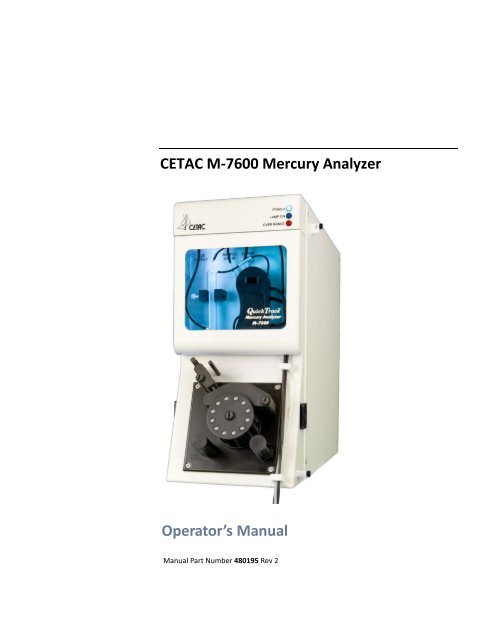
CETAC M-7600 Mercury Analyzer Operator's Manual
CETAC M-7600 Mercury Analyzer Operator's Manual
CETAC M-7600 Mercury Analyzer Operator's Manual

You also want an ePaper? Increase the reach of your titles
YUMPU automatically turns print PDFs into web optimized ePapers that Google loves.
<strong>CETAC</strong> M-<strong>7600</strong> <strong>Mercury</strong> <strong>Analyzer</strong><br />
Operator’s <strong>Manual</strong><br />
<strong>Manual</strong> Part Number 480195 Rev 2
COPYRIGHT<br />
© 2008, 2012 <strong>CETAC</strong> Technologies<br />
480195 Rev 2 , October, 2012<br />
<strong>CETAC</strong> Technologies authorizes its customers<br />
to reproduce, transmit, or store this document<br />
in its entirety, including this page, for the<br />
express purpose of installing, operating, or<br />
maintaining the product described herein.<br />
<strong>CETAC</strong> Technologies<br />
Customer Service & Support<br />
14306 Industrial Road<br />
Omaha, Nebraska 68144, USA<br />
Phone (800) 369-2822 (USA only)<br />
Phone (402) 733-2829<br />
Fax (402) 733-1932<br />
E-mail custserv@cetac.com<br />
REVISIONS<br />
<strong>CETAC</strong> Technologies strives to provide the<br />
scientific community with an unparalleled<br />
combination of effective technology and<br />
continuing value. Modular upgrades for<br />
existing instruments will continue to be a<br />
prime consideration as designs progress.<br />
<strong>CETAC</strong> Technologies reserves the right to<br />
revise this document and/or improve<br />
products described herein at any time without<br />
notice or obligation. Warranty registration<br />
entitles the named owner exclusively to<br />
manual change pages/new editions as they<br />
are published.<br />
TRADEMARK ACKNOWLEDGEMENTS<br />
Windows is a registered trademark of<br />
Microsoft Corporation in the United States and<br />
other countries.<br />
Nafion ® is a registered trademark of DuPont<br />
(E.I. du Pont de Nemours and Company).<br />
Perma Pure is a registered trademark of<br />
Perma Pure LLC.<br />
DuPont, Kapton®, Teflon®, Tefzel® and<br />
Viton® are trademarks or registered<br />
trademarks of E.I. du Pont de Nemours and<br />
Company.<br />
PharMed and Tygon are registered<br />
trademarks of Saint-Gobain Performance<br />
Plastics.<br />
Santoprene is a trademark of Exxon Mobil.<br />
KIMWIPES is a registered trademark and<br />
KIMTECH SCIENCE is a trademark of<br />
Kimberly-Clark Worldwide, Inc<br />
All other marks are the property of their<br />
respective owners.
Contents<br />
1 Introduction .............................................................................................................. 7<br />
Overview.................................................................................................................................... 7<br />
About This Book ..................................................................................................................... 7<br />
Who Should Use This Product ................................................................................... 7<br />
Where to Go for More Information ................................................................................ 8<br />
System Features ..................................................................................................................... 9<br />
System Performance Characteristics .......................................................................... 10<br />
Overview of the <strong>Mercury</strong> <strong>Analyzer</strong> .............................................................................. 11<br />
Supplied Equipment ........................................................................................................... 13<br />
Equipment and Supplies ................................................................................................... 14<br />
Required Equipment and Supplies ........................................................................ 14<br />
Recommended Supplies ............................................................................................. 15<br />
2 Preparing for Installation ................................................................................. 17<br />
Establishing Optimal Operating Conditions ............................................................ 17<br />
Creating the Lab Environment ............................................................................... 17<br />
Choosing a Location ............................................................................................................ 18<br />
Space Requirements .................................................................................................... 18<br />
Work Surface Requirements .................................................................................... 20<br />
Ventilation Requirements ................................................................................................ 20<br />
Power Requirements ......................................................................................................... 20<br />
Unpacking the <strong>Mercury</strong> <strong>Analyzer</strong> ................................................................................. 21<br />
3 Installing the <strong>Analyzer</strong> ....................................................................................... 25<br />
Installation Overview......................................................................................................... 25<br />
Step 1: Position the <strong>Mercury</strong> <strong>Analyzer</strong> and Autosampler.................................. 26<br />
Step 2: Connect the Autosampler Peristaltic Pump to the Rinse Station .... 26<br />
Step 3: Set Up the Autosampler ..................................................................................... 30<br />
Step 4: Connect Power and Data Cables to the Back of the <strong>Mercury</strong><br />
<strong>Analyzer</strong> .......................................................................................................................... 39<br />
Step 5: Connect the Carrier Gas Tubing ..................................................................... 40<br />
Step 6: Install the <strong>Mercury</strong> Trap (KMnO 4) ................................................................ 42<br />
Step 7: Connect the Back of the Autosampler ......................................................... 44<br />
Step 8: Connect to the Host Computer ....................................................................... 45<br />
Summary ......................................................................................................................... 45<br />
Installing a Secondary NIC in Your Own PC ...................................................... 45<br />
Connecting the Communication Cables............................................................... 46<br />
Configuring the Network Metrics .......................................................................... 46<br />
Setting the IP Address for the Secondary NIC ................................................... 50<br />
Changing the Subnet of the <strong>Mercury</strong> <strong>Analyzer</strong>................................................. 51<br />
Connecting a Laptop Computer to the M-<strong>7600</strong> ................................................ 52<br />
Step 9: Install the Gas-Liquid Separator (GLS) ....................................................... 53
M-<strong>7600</strong> <strong>Mercury</strong> <strong>Analyzer</strong> Operator’s <strong>Manual</strong><br />
Contents<br />
Step 10: Connect the Peristaltic Pump on the <strong>Mercury</strong> <strong>Analyzer</strong> .................. 57<br />
Installing the Peristaltic Pump Tubing ............................................................... 57<br />
Installing the Mixing Tee and Drain Tees .......................................................... 59<br />
Step 11: Power On and Verify Communication ...................................................... 63<br />
To Configure the Network Connection ................................................................ 63<br />
To Power On the System for the First Time (PC Configured by <strong>CETAC</strong>) 64<br />
To Power On the System for the First Time (Customer-Supplied PC) ..... 64<br />
To Test the Autosampler ........................................................................................... 68<br />
Step 12: Fill the Rinse Solution Bottle ........................................................................ 68<br />
Step 13: Fill the Reagent Bottle ..................................................................................... 69<br />
Preserving the SnCl 2 ................................................................................................... 69<br />
Step 14: Adjust the Peristaltic Pump Tubing Clamp Tension (Optional) ... 70<br />
Step 15: Check the Reagent Flow ................................................................................. 73<br />
Step 16: Check the Sample Probe Flow ..................................................................... 73<br />
4 Using the <strong>Analyzer</strong> ............................................................................................... 75<br />
Theory of Operation ........................................................................................................... 75<br />
Autosampler .................................................................................................................. 75<br />
QuickTrace M-<strong>7600</strong> Automated <strong>Mercury</strong> <strong>Analyzer</strong> .................................... 76<br />
Software................................................................................................................................... 78<br />
Preparing Reagents and Calibration Standards ..................................................... 79<br />
Gas Parameters .................................................................................................................... 81<br />
Starting the System............................................................................................................. 81<br />
<strong>Mercury</strong> Vapor Lamp Warmup .............................................................................. 82<br />
Turning Off the <strong>Mercury</strong> Vapor Lamp for System Warm-Up ..................... 82<br />
System Warm-Up for Trace or Ultra-Trace Analysis ..................................... 82<br />
System Warm-Up for ppb or Non-Ultra-Trace Analysis ............................... 83<br />
Wetting the GLS .................................................................................................................... 84<br />
Running the Interactive Demo ...................................................................................... 87<br />
Overview of the <strong>CETAC</strong> QuickTrace Software ..................................................... 87<br />
Learning More .............................................................................................................. 88<br />
QuickTrace M-<strong>7600</strong> Startup Summary ................................................................... 89<br />
Setting Baseline Correction ............................................................................................ 91<br />
Keeping an Instrument Log Book .......................................................................... 91<br />
Viewing the Graphs ..................................................................................................... 92<br />
Setting a One-Point Baseline ................................................................................... 92<br />
Setting a Two-Point Baseline .................................................................................. 94<br />
Summary of Gas and Liquid Flows for Analytical Ranges of the<br />
QuickTrace M-<strong>7600</strong> ................................................................................................ 98<br />
Placing the QuickTrace M-<strong>7600</strong> in Standby Mode ......................................... 100<br />
Cold Shutdown .................................................................................................................. 101<br />
Summary of QuickTrace M-<strong>7600</strong> Shut Down .............................................. 101<br />
5 Maintaining the <strong>Mercury</strong> <strong>Analyzer</strong> ............................................................. 103<br />
Maintenance Schedule ................................................................................................... 103<br />
Daily Maintenance (Always Check Before Analysis) .................................... 103<br />
Weekly Maintenance ................................................................................................ 104<br />
Monthly Maintenance .............................................................................................. 104<br />
Yearly Maintenance .................................................................................................. 104<br />
Autosampler Yearly Maintenance....................................................................... 105<br />
Removal or Inspection of the Sample Cell ............................................................. 105<br />
Opening the Optics Access Panel ......................................................................... 105<br />
Removing the Sample Cell ...................................................................................... 107<br />
4
M-<strong>7600</strong> <strong>Mercury</strong> <strong>Analyzer</strong> <strong>Operator's</strong> <strong>Manual</strong><br />
Contents<br />
Cleaning the Cell Windows ........................................................................................... 107<br />
Quick Exposed Surface Cleaning ......................................................................... 107<br />
Dismantling for Total Cleaning ........................................................................... 109<br />
Cell Assembly...................................................................................................................... 109<br />
Cleaning the Gas-Liquid Separator ........................................................................... 112<br />
Changing the Cell Gas Tubing ...................................................................................... 113<br />
Retubing the Gas-Liquid Separator .......................................................................... 115<br />
GLS Inlet........................................................................................................................ 115<br />
GLS Drain ..................................................................................................................... 116<br />
Replacing the Perma Pure ® Dryer Cartridge ........................................................ 117<br />
GLS Overflow Recovery .................................................................................................. 119<br />
Replacing the Hg Lamp Bulb ........................................................................................ 124<br />
When to Replace or Service the Lamp .............................................................. 124<br />
Cleaning the EOFM ................................................................................................... 124<br />
Getting a Replacement Lamp ............................................................................... 125<br />
Caring for the Lamp ................................................................................................. 126<br />
Replacing the Lamp ................................................................................................. 126<br />
Adjusting the Lamp Current ................................................................................. 129<br />
Replacing the Fuse ........................................................................................................... 131<br />
6 Troubleshooting the <strong>Mercury</strong> <strong>Analyzer</strong> .................................................... 133<br />
Troubleshooting Communication Issues ............................................................... 133<br />
Step 1: Check the Cable ........................................................................................... 133<br />
Step 2: Use the IPSetup Tool to Check the Configuration .......................... 133<br />
Step 3: Check the Subnet Configuration Using the Define QuickTrace<br />
Hardware Tool .................................................................................................. 134<br />
Step 4: Check for an IP address conflict ........................................................... 137<br />
If the IPSetup Tool Does Not Find the M-<strong>7600</strong> .............................................. 138<br />
"Subnet of this PC and the M-<strong>7600</strong> are Not Compatible" Error ............. 139<br />
Cannot Zero Instrument ................................................................................................ 140<br />
"Integration Adjustment Reached" Messages ...................................................... 140<br />
Drifting Baseline ................................................................................................................ 140<br />
Low Absorbance or No <strong>Mercury</strong> Response ........................................................... 141<br />
No Liquid or Gas Flow .................................................................................................... 141<br />
No Sample or Rinse Flow ....................................................................................... 141<br />
No SnCl 2 Flow ............................................................................................................. 142<br />
No Drain Flow ............................................................................................................ 142<br />
No Gas Flow or Low Gas Flow .............................................................................. 142<br />
Double Peak with Low Absorbance .......................................................................... 142<br />
Poor Reproducibility ....................................................................................................... 143<br />
Noisy Baseline .................................................................................................................... 144<br />
Bad DL .................................................................................................................................... 144<br />
Sudden Standard Absorbance Rise During Run .................................................. 144<br />
Poor Accuracy .................................................................................................................... 145<br />
Returning the Product to <strong>CETAC</strong> for Service ........................................................ 146<br />
Shipping the Product ............................................................................................... 146<br />
Product Warranty Statement .............................................................................. 146<br />
Returned Product Procedures .............................................................................. 147<br />
Returned Product Warranty Determination ................................................. 147<br />
7 Safety and Regulatory Information ............................................................. 149<br />
Characteristics ................................................................................................................... 149<br />
Environmental Characteristics ............................................................................ 149<br />
5
M-<strong>7600</strong> <strong>Mercury</strong> <strong>Analyzer</strong> Operator’s <strong>Manual</strong><br />
Contents<br />
Electrical Characteristics ....................................................................................... 150<br />
Safety Notices ..................................................................................................................... 151<br />
Replacement Parts .................................................................................................... 151<br />
Chemical Hazards ...................................................................................................... 151<br />
Power Cord Set Requirements .............................................................................. 151<br />
Power Cord Safety Maintenance ......................................................................... 151<br />
Grounding ..................................................................................................................... 152<br />
Mains Disconnect ....................................................................................................... 152<br />
Mechanical Hazards ................................................................................................. 152<br />
Cleaning Instructions ............................................................................................... 153<br />
Operating Environment .......................................................................................... 153<br />
Explanation of Caution and Warning Notices ............................................... 154<br />
Avertissements en Français ......................................................................................... 155<br />
Electromagnetic Interference ..................................................................................... 156<br />
Explanation of Regulatory Marks .............................................................................. 156<br />
8 Glossary ................................................................................................................. 157<br />
6
1 Introduction<br />
Overview<br />
The <strong>CETAC</strong> QuickTrace M-<strong>7600</strong> mercury analyzer measures trace levels of<br />
mercury in aqueous solution by Cold Vapor Atomic Absorption Spectrometry<br />
(CVAAS). CVAAS does not require heating the sample with a flame, plasma, or<br />
furnace. The mercury analyzer’s modular design permits remarkably easy<br />
maintenance access and a reduced countertop footprint. Sturdy construction,<br />
drift-stabilized double beam optics, thermal and electro-optical lamp<br />
stabilization, and an unusually stable “non-foaming” Gas-Liquid Separator (U.S.<br />
Patent #5,792,663) collectively afford exceptional structural integrity and<br />
signal stability. The QuickTrace M-<strong>7600</strong> exhibits a high signal-to-noise ratio<br />
and ultra-trace detection limits for an absorbance system that is fully<br />
compliant with EPA CVAA methods such as 245.7, 245.1, 245.5, SW846 7470<br />
and 7471.<br />
About This Book<br />
This document describes the procedures for installing, using, and maintaining<br />
the analyzer.<br />
This manual covers the following products:<br />
‣ <strong>CETAC</strong> QuickTrace M-<strong>7600</strong> mercury analyzer<br />
Who Should Use This Product<br />
The primary audience for this manual consists of mercury detection and<br />
mercury measurement laboratory managers, chemists, technicians, fieldservice<br />
engineers and owners of the QuickTrace M-<strong>7600</strong> mercury analyzer.<br />
To use this product effectively, you should have a basic knowledge of mercury<br />
analysis, at least a beginning level of computer experience, and a basic<br />
knowledge of chemical handling procedures including the handling of<br />
organomercurials.<br />
Before operating the QuickTrace M-<strong>7600</strong> analyzer, autosampler, or optional<br />
ADX-500 autodilutor, it is important to read this manual, the QuickTrace<br />
Software <strong>Manual</strong>, the Autosampler Operator’s <strong>Manual</strong>, and (if applicable) the<br />
ADX-500 Autodilutor Accessory Operator’s <strong>Manual</strong>.
Operator’s <strong>Manual</strong><br />
Chapter 1: Introduction<br />
Where to Go for More Information<br />
In addition to this manual, you can refer to the following resources:<br />
‣ The QuickTrace Software <strong>Manual</strong> and built-in help<br />
‣ The M-<strong>7600</strong> <strong>Mercury</strong> <strong>Analyzer</strong> PC Setup Guide<br />
‣ The <strong>CETAC</strong> Autosampler Operator’s <strong>Manual</strong><br />
‣ The ADX-500 Autodilutor <strong>Manual</strong> (optional)<br />
‣ U.S. EPA Method 245.1; method for Hg determination in drinking water<br />
‣ U.S. EPA Method 245.7; <strong>Mercury</strong> in Water by Atomic Fluorescence<br />
Spectrometry<br />
‣ U.S. EPA, Office of Solid Wastes. SW846 Method 7470A; <strong>Mercury</strong> in Liquid<br />
Waste (Cold-Vapor Technique)<br />
‣ U.S. EPA, Office of Solid Wastes, SW846 Method 7471B; <strong>Mercury</strong> in Solid or<br />
Semisolid Waste (Cold-Vapor Technique)<br />
‣ American Society for Testing and Methods. ASTM D3223-91; Standard Test<br />
Method for Total <strong>Mercury</strong> in Water<br />
‣ The <strong>CETAC</strong> Technologies Web site: www.cetac.com<br />
‣ <strong>CETAC</strong> Technologies Customer Service and Support:<br />
1 (800) 369-2822 (USA only)<br />
1 (402) 733-2829<br />
1 (402) 733-1932 (Fax)<br />
E-mail: custserv@cetac.com<br />
8
<strong>CETAC</strong> QuickTrace M-<strong>7600</strong> <strong>Mercury</strong> <strong>Analyzer</strong><br />
Chapter 1: Introduction<br />
System Features<br />
The QuickTrace M-<strong>7600</strong> incorporates the following features to form an<br />
automated, integrated mercury analysis system.<br />
‣ Computer-controlled four-channel high-performance peristaltic pump<br />
(12-roller pump head).<br />
‣ Ozone-free Hg Lamp. No lamp ventilation is needed.<br />
‣ Thermally controlled Hg lamp housing (for a stabilized Hg vapor lamp).<br />
‣ Stable high performance Gas-Liquid Separator (GLS). (U.S. Patent<br />
#5,792,663). Non-foaming/non-bubbling “thin liquid film” GLS design,<br />
which allows trouble-free direct analysis of blood, urine, and fish tissue<br />
digests as well as standard water and waste analysis.<br />
‣ Rigid, shock and vibration-isolated optical rail (mounting the Hg lamp,<br />
collimator lens, absorption tubes, camera, CCD detector, and A/D<br />
converter).<br />
‣ Precise, self-aligning optical mounts, no optical alignment required,<br />
maximizing the convenience of instrument baseline zeroing. This design<br />
extends maintenance intervals without loss of performance.<br />
‣ Long path (220 mm) absorbance cells.<br />
‣ Hg lamp electro-optical feedback beam utilizing a high-performance solidstate<br />
detector for ultra-fine lamp stabilization.<br />
‣ Fixed optical interference filters, three each (254 ± 2 nm wavelength, 20%<br />
T, 12.7 mm dia.). No moving parts.<br />
‣ Standard Perma Pure ® dryer cartridge eliminates the need for Mg(ClO 4) 2<br />
drying agent.<br />
‣ Stabilized double beam optics - traditional double-beam (sample and<br />
reference) with a CCD detector.<br />
‣ Internal ADC (Analog-to-Digital Conversion).<br />
‣ High-rate data sampling.<br />
‣ Computer controlled system shutdown/standby routines.<br />
‣ Integrated optional autosamplers for accommodation of calibration<br />
standards and up to 720 samples.<br />
‣ Ethernet communications.<br />
‣ Gas exhaust Hg vapor safety trap (solid crystalline KMnO 4).<br />
9
Operator’s <strong>Manual</strong><br />
Chapter 1: Introduction<br />
System Performance Characteristics<br />
‣ Ultra-trace detection limits: < 0.5 ppt at 40 mL / min. carrier gas flow 1 .<br />
(Direct steady state absorbance mode, without pre-concentration by gold<br />
amalgamation).<br />
‣ Wide dynamic linear working range, ≅ 4 orders of magnitude.<br />
‣ Short term precision (%RSD @ 95% Confidence) < 6.0% @ 5 ppt, n=5<br />
‣ Short term precision (%RSD @ 95% Confidence) < 1.2% @ 20 ppt, n=5<br />
‣ Long term precision (%RSD @ 95% Confidence) < 2.7%/h @ 200.0 ppt<br />
‣ 99% Confidence Accuracy @ 5 ppt; ±3.1%<br />
‣ 99% Confidence Accuracy @ 20 ppt; ±4.3%<br />
‣ Sample Throughput < 3.5 min/sample at IDL<br />
‣ Ultra-low drift rates ≤ 300 µAbs/hr (after warm-up) raw uncorrected<br />
analog baseline on-screen drifts.<br />
‣ Ultra-low short-term absorbance noise ≤ 200 µAbs (10 -5 Abs).<br />
‣ 0.1% “raw” Hg lamp stability (single beam output).<br />
‣ Unusually fast washout ≈ 240 sec. from 1ppm Hg, at 1000 mL/min gas<br />
flow.<br />
‣ <strong>Mercury</strong> Response: ≥ 14,000 µAbs / ppb 2 at 100 mL/min carrier gas flow.<br />
1 One hour minimum warm-up using the standard Nafion ® dryer and a gas flow equal<br />
to 40 mL/min along with prescribed tubing and reagents. Using pump speed, uptake<br />
and rinse times specified for standard Nafion ® dryer in Table 4-1 (p. 72), and ≥12 s<br />
integration cycle selected on the "flattest" portion of the peak time profile.<br />
2 Using prescribed tubing, reagents, and pump speed.<br />
10
<strong>CETAC</strong> QuickTrace M-<strong>7600</strong> <strong>Mercury</strong> <strong>Analyzer</strong><br />
Chapter 1: Introduction<br />
Overview of the <strong>Mercury</strong> <strong>Analyzer</strong><br />
Power and Status Lights<br />
Perma Pure ® Dryer Cartridge<br />
Gas-Liquid Separator (GLS)<br />
Peristaltic Pump<br />
Figure 1-1<br />
M-<strong>7600</strong> <strong>Mercury</strong> <strong>Analyzer</strong>—Front View.<br />
Sample Probe<br />
Rinse Bottle<br />
Autosampler<br />
(ASX-520 is shown)<br />
Reagent Bottle<br />
Figure 1-2<br />
M-<strong>7600</strong> <strong>Mercury</strong> <strong>Analyzer</strong>—Front View with Autosampler.<br />
11
Operator’s <strong>Manual</strong><br />
Chapter 1: Introduction<br />
Autosampler<br />
Peristaltic Pump<br />
<strong>Mercury</strong> Trap<br />
Autosampler<br />
Power Switch<br />
Electrical<br />
Connectors<br />
M-<strong>7600</strong><br />
Power Switch<br />
Figure 1–2<br />
M-<strong>7600</strong> <strong>Mercury</strong> <strong>Analyzer</strong> —Back View of Complete System.<br />
Auxiliary I/O Ports<br />
Ethernet Port<br />
Auxiliary Input Port<br />
Auxiliary Power<br />
Ports<br />
M-<strong>7600</strong><br />
Power Switch<br />
M-<strong>7600</strong><br />
Power Cord<br />
Figure 1-3<br />
M-<strong>7600</strong> <strong>Mercury</strong> <strong>Analyzer</strong> —Electrical Connectors.<br />
The following components are located on the front of the mercury analyzer<br />
(see Figure 1-2).<br />
‣ POWER Indicator. The top blue LED indicates that the analyzer is<br />
connected to a power source and turned on.<br />
‣ LAMP ON Indicator. Indicates when the internal mercury vapor lamp is<br />
turned on.<br />
‣ OVER RANGE Indicator. Indicates that the internal mercury vapor lamp is<br />
drawing more than the recommended amount of current. This LED will<br />
glow for a few seconds while the mercury lamp warms up when the<br />
mercury analyzer is first turned on and the QuickTrace software is<br />
started or any time the lamp is off and then powered on via software<br />
controls.<br />
‣ Perma Pure ® Dryer Cartridge. Uses a DuPont Nafion ® membrane to<br />
remove humidity from the sample gas.<br />
‣ Gas-Liquid Separator (GLS).<br />
‣ Front Cover. Protects the GLS and dryer cartridge. An LED lamp<br />
illuminates the area behind the cover whenever the mercury analyzer is<br />
turned on.<br />
12
<strong>CETAC</strong> QuickTrace M-<strong>7600</strong> <strong>Mercury</strong> <strong>Analyzer</strong><br />
Chapter 1: Introduction<br />
‣ Peristaltic Pump. A four-channel peristaltic pump is built into the front of<br />
the mercury analyzer.<br />
The following components are located on the back of the analyzer:<br />
‣ POWER Switch. Turns power to the M-<strong>7600</strong> mercury analyzer on and off.<br />
This switch also controls power to the autosampler, when powered<br />
through the mercury analyzer.<br />
‣ Gas Ports. Gas inlet and exhaust ports.<br />
‣ <strong>Mercury</strong> Trap. The trap scrubs mercury from the exhaust gas.<br />
The following electrical connectors are located on the back of the analyzer:<br />
‣ Ethernet Port. The Ethernet port is used to interface the mercury<br />
analyzer with the host computer.<br />
‣ Auxiliary Communication Ports. The two AUX I/O ports and one AUX<br />
INPUT port are reserved for use with other <strong>CETAC</strong> instruments.<br />
‣ Power Output Connectors. Provides power for the autosampler and for<br />
an optional auxiliary device.<br />
Supplied Equipment<br />
The following standard components are supplied with the mercury analyzer:<br />
‣ M-<strong>7600</strong> <strong>Mercury</strong> <strong>Analyzer</strong>.<br />
‣ CD. The CD contains:<br />
• QuickTrace software<br />
• This manual<br />
• Other application-specific information<br />
‣ Gas-Liquid Separator.<br />
‣ Perma Pure ® Dryer Cartridge. Uses a DuPont Nafion ® membrane to<br />
remove humidity from the sample gas. The cartridge is pre-installed in the<br />
mercury analyzer.<br />
‣ KMnO 4 Absorbent Trap. This scrubs mercury from the exhaust gas. The<br />
KMnO 4 is not included.<br />
‣ Bottles. One reagent bottle and one rinse bottle are provided.<br />
‣ PCI Ethernet Adapter Board.<br />
‣ Power Cord and Cables. An Ethernet cable, a power cord for the mercury<br />
analyzer, and a power cord for the autosampler are supplied.<br />
Depending on how the system was ordered, the following optional equipment<br />
may be supplied:<br />
‣ Computer. The mercury analyzer may be ordered with a computer which<br />
is pre-configured with the QuickTrace software.<br />
‣ <strong>CETAC</strong> ASX-520/260/130 Autosampler.<br />
‣ <strong>CETAC</strong> ADX-500 Autodilutor.<br />
‣ ENC-500 Enclosure.<br />
13
Operator’s <strong>Manual</strong><br />
Chapter 1: Introduction<br />
WARNING<br />
The computer, autosampler, and optional accessories have their own<br />
manuals (printed or on CD-ROM). Before using the equipment, read those<br />
manuals to understand the precautions you must take to avoid possible<br />
hazards.<br />
Equipment and Supplies<br />
Required Equipment and Supplies<br />
‣ Inert Gas Regulator.<br />
Two-stage, 10-200 psig (70-1380 kPa) secondary pressure gauge, with<br />
plumbing couple for either a cylinder or Dewar capable of delivering 150<br />
psig (1040 kPa).<br />
‣ AC Power Strip.<br />
Surge protected with six outlets, 15-20 A.<br />
‣ Cylinder or Dewar, UHP Nitrogen or Argon Gas.<br />
Ultra-high purity, dry, research grade N 2 or 99.999% purity Ar. The<br />
QuickTrace M-<strong>7600</strong> has a user replaceable 2-micron filter, which<br />
prevents damage from particulates to the internal gas control components.<br />
‣ <strong>Mercury</strong> Standard Solution.<br />
1000 ppm (minimum order quantity).<br />
‣ Hydrochloric Acid Trace Metal Grade (37%).<br />
Trace metal HCl will be used in the preparation of Hg standards, SnCl 2<br />
reagent and in some method applications. If an application is more<br />
demanding, a better grade of acid may be needed (for example, double<br />
distilled).<br />
‣ Nitric Acid Trace Metal Grade (68-70%).<br />
Trace metal HNO 3 will be used in sample preparation, cleaning glassware<br />
(lab glassware and the QuickTrace Gas-Liquid Separator) and added to<br />
the QuickTrace rinse solution to help maintain the cleanliness of the<br />
system during operation.<br />
‣ Stannous Chloride (Crystals, Di-Hydrate).<br />
Two 500g containers minimum order, “suitable for Hg determination.” The<br />
stock SnCl 2 is introduced into the QuickTrace at a steady flow rate and<br />
therefore any mercury contamination will be negated during the<br />
instrument zero.<br />
‣ Potassium Permanganate. Solid, Crystalline.<br />
The least expensive available grade at a minimum quantity is sufficient<br />
unless it is also to be used for oxidative sample preparation. This lowgrade<br />
reagent stock is sufficient to fill a safety trap for retention of Hg<br />
vapor exhaust from the instrument.<br />
‣ 2-propanol. High Purity, “Spectrophotometric” Grade.<br />
2-propanol will be used for cleaning the optical cells and cell windows.<br />
14
<strong>CETAC</strong> QuickTrace M-<strong>7600</strong> <strong>Mercury</strong> <strong>Analyzer</strong><br />
Chapter 1: Introduction<br />
‣ KIMTECH SCIENCE KIMWIPES® Delicate Task Wipers.<br />
‣ Additional Chemical Compounds.<br />
The sample preparation procedures of the intended analytical method may<br />
require additional chemical compounds. Refer to published method<br />
specifications.<br />
Recommended Supplies<br />
‣ Volumetric flasks 100 mL class A (TC) six each.<br />
‣ Volumetric flasks 1000 mL class A (TC) two each.<br />
‣ Precision air displacement micropipettes, 10 to 10,000 µL (TD).<br />
‣ Replacement tips for micropipettes.<br />
‣ Disposable plastic dropping pipettes.<br />
‣ Graduated cylinders, 10 and 100 mL.<br />
‣ Polypropylene or polyethylene bottle with Cap, 1 L.<br />
‣ Weighing balance, top loading, 0.1 g readability (or better), any available<br />
capacity will work (1.1 kg capacity is good).<br />
‣ Laboratory scoopula and large spatula.<br />
‣ Stopwatch (for measuring liquid uptake rates).<br />
‣ Stirring rod.<br />
‣ Powder funnel, wide bore stem, small overall size.<br />
‣ Wrenches, adjustable 12" and 6".<br />
‣ Screw drivers:<br />
• 1 small Phillips<br />
• 1 medium Phillips<br />
• 1 long-shank medium flat-blade<br />
• 1 small thin flat-blade<br />
‣ Deionized water.<br />
‣ Flow meter 0 – 1,500 mL/min. with 1 mL/min. readability, calibrated to<br />
user’s choice of carrier gas (Ar or N 2).<br />
15
Operator’s <strong>Manual</strong><br />
Chapter 1: Introduction<br />
This page is intentionally blank.<br />
16
2 Preparing for<br />
Installation<br />
Installing the analyzer requires preparation. Before you install the analyzer,<br />
you should evaluate the physical arrangement of the laboratory to choose a<br />
suitable location. Once you choose a location, you must carefully unpack the<br />
analyzer prior to beginning the installation.<br />
This chapter discusses what requirements must be met when you choose a<br />
location. It also describes how to unpack the equipment before installation.<br />
Establishing Optimal Operating Conditions<br />
The mercury analyzer operates reliably even under less than ideal conditions.<br />
It is not, however, indestructible. Malfunction or damage can occur if specific<br />
operating conditions are not met. Meeting these conditions requires that you<br />
create the proper lab environment, replace analyzer components that wear out<br />
under normal use, and purchase the appropriate supplies for use with the<br />
analyzer.<br />
NOTE<br />
Damage or malfunction that results from unsatisfactory operating conditions<br />
may constitute misuse and abuse and be excluded from warranty coverage.<br />
Creating the Lab Environment<br />
To create satisfactory operating conditions in your lab environment, follow<br />
these guidelines:<br />
‣ Operate the analyzer in a conventional lab environment where the<br />
temperature is 60–90 °F (15–32 °C), the humidity is 20–70%<br />
non-condensing, and the unit is not exposed to excessive flammable or<br />
corrosive materials.<br />
‣ Avoid rough handling of the analyzer. If possible, do not expose the<br />
analyzer to vibration or shock.<br />
17
Operator’s <strong>Manual</strong><br />
Chapter 2: Preparing for Installation<br />
‣ Protect the analyzer from long-term exposure to condensation, corrosive<br />
materials, solvent vapor, continual standing liquids.<br />
‣ Observe the same general electrostatic discharge precautions as with any<br />
other integrated circuit electronic devices. Low humidity environments,<br />
especially when combined with static-generating materials, require<br />
maximum care.<br />
CAUTION<br />
Discharge static buildup and ground to the analyzer base or cabinet before<br />
performing any maintenance. Do not touch or short-circuit bare contacts or<br />
connectors.<br />
‣ Avoid using the analyzer if strong electromagnetic interference or radio<br />
frequency interference is present. Interference fields can cause erratic<br />
operation of the analyzer.<br />
Choosing a Location<br />
Space Requirements<br />
The QuickTrace M-<strong>7600</strong> <strong>Mercury</strong> <strong>Analyzer</strong> System includes the base unit, PC<br />
with monitor, reagent and rinse bottles, and an optional autosampler.<br />
A typical system requires a minimum footprint for countertop installation of<br />
183cm (6’) X 31cm (2’) X 91cm (3’) (W x D x H). A floor space of 1’ (30cm) X 1’<br />
(30cm) is required for the liquid waste receptacle. The space for the waste can<br />
be directly below the analyzer, or directly in front of the lab bench and in line<br />
with the peristaltic pump.<br />
86 cm (34 inches)<br />
183 cm (6 feet)<br />
Figure 2-1 Footprint of QuickTrace M-<strong>7600</strong> <strong>Mercury</strong> <strong>Analyzer</strong><br />
with ASX-520 Autosampler.<br />
18
<strong>CETAC</strong> QuickTrace M-<strong>7600</strong> <strong>Mercury</strong> <strong>Analyzer</strong><br />
Chapter 2: Preparing for Installation<br />
71 cm (28 inches)<br />
142 cm (56 inches)<br />
Figure 2-2 Footprint of QuickTrace M-<strong>7600</strong> <strong>Mercury</strong> <strong>Analyzer</strong><br />
with ASX-260 Autosampler.<br />
71 cm (28 inches)<br />
142 cm (56 inches)<br />
Figure 2-3 Footprint of QuickTrace M-<strong>7600</strong> <strong>Mercury</strong> <strong>Analyzer</strong><br />
with ASX-130 Autosampler.<br />
46 cm<br />
(18.1 in)<br />
20 cm<br />
(7.9 inches)<br />
56 cm<br />
(22.0 inches)<br />
Figure 2-4 Dimensions of the QuickTrace M-<strong>7600</strong> <strong>Mercury</strong> <strong>Analyzer</strong>.<br />
The work surface should be at least 61 cm (24 inches) deep if it is accessible<br />
from both front and back. If the work surface is against a wall, it should be at<br />
least 76 cm (30 inches, if possible) deep. If possible, allow at least 15 cm (6<br />
inches) behind the system for cable egress, ventilation, and access to the<br />
power switches.<br />
19
Operator’s <strong>Manual</strong><br />
Chapter 2: Preparing for Installation<br />
Always position the equipment so that it is easy to disconnect the power cord.<br />
Work Surface Requirements<br />
The analyzer must be placed on a sturdy countertop or table. It is not<br />
recommended to place the analyzer on a wheeled cart or folding table.<br />
If the analyzer is to be used in an earthquake zone, choose a location or secure<br />
it so that it will not fall and cause injury or damage during an earthquake.<br />
Ventilation Requirements<br />
During operation, the QuickTrace M-<strong>7600</strong> internally contains trace amounts<br />
of mercury vapor. To prevent inhalation of the vapor, the QuickTrace M-<strong>7600</strong><br />
uses a solid KMnO 4 absorbent trap located on the back of the instrument. This<br />
trap absorbs the mercury vapor prior to final exhaust; therefore no extra<br />
ventilation is required beyond that of a standard laboratory environment.<br />
WARNING<br />
INHALATION HAZARD<br />
Gases exhausting from the QuickTrace M-<strong>7600</strong> cabinet prior to the<br />
external Hg vapor trap (affixed to the rear cabinet panel) contain traces of<br />
mercury vapor and will cause injury if inhaled. Do not run the QuickTrace<br />
M-<strong>7600</strong> unless exhausted gas is properly “scrubbed” or removed. Fill,<br />
maintain, and use the provided KMnO 4 absorbent trap or run a transfer line<br />
to a fume hood.<br />
The ambient temperature should be kept as stable as possible. Locating the<br />
QuickTrace M-<strong>7600</strong> directly in the path of an air conditioner or heater vent<br />
may cause baseline drift, and is not recommended.<br />
NOTE<br />
Due to the likelihood of accelerated damage from corrosion and dust, locating<br />
the QuickTrace M-<strong>7600</strong> in a fume hood with stagnant air automatically voids<br />
the warranty.<br />
Power Requirements<br />
The QuickTrace M-<strong>7600</strong> mercury analyzer includes a built-in switching<br />
power supply which supports line voltages in the range 100-240 VAC at<br />
frequencies of 50-60 Hz. See “Electrical Characteristics” on page 150 for<br />
detailed power requirements.<br />
The autosampler is powered by the M-<strong>7600</strong>'s AUX POWER output. See the<br />
autosampler manual for more details.<br />
The power requirements for the computer can be found on the label affixed to<br />
the bottom of the computer, or in the computer manual which can be found on<br />
the computer CD.<br />
Place the QuickTrace M-<strong>7600</strong> within 1.2 meters of a standard power outlet.<br />
Ensure that you position the analyzer so that the location where the power<br />
supply cord plugs into it is easily accessible (is not blocked) and it can be<br />
20
<strong>CETAC</strong> QuickTrace M-<strong>7600</strong> <strong>Mercury</strong> <strong>Analyzer</strong><br />
Chapter 2: Preparing for Installation<br />
quickly disconnected if needed. In case of hazard, the analyzer should be<br />
disconnected from the power source.<br />
Three power outlets may be required, one each for the QuickTrace M-<strong>7600</strong><br />
mercury analyzer, computer, and monitor. (An AC surge protected power strip<br />
with six or more outlets will suffice).<br />
The supplied power cord meets the requirements of the country where the<br />
instrument was purchased. If the instrument is to be used in a country other<br />
than the one specified at the time of ordering, obtain a new power cord set that<br />
meets the requirements of that country.<br />
WARNING<br />
SHOCK HAZARD<br />
This equipment is designed for connection to a grounded (earthed) outlet.<br />
The grounding type plug is an important safety feature. For continued<br />
protection against electrical shock or damage to the instrument, do not<br />
disable this feature.<br />
Do not apply power to the power supply until ready to operate the analyzer.<br />
Unpacking the <strong>Mercury</strong> <strong>Analyzer</strong><br />
Inspect external packaging upon receipt for signs of shipping damage. Inspect<br />
all items during unpacking and notify the carrier immediately of any concealed<br />
damage.<br />
If the system is shipped or removed from storage during cold weather, allow<br />
the packaged equipment to equilibrate to room temperature before opening<br />
and exposing to warm, humid air. It is usually sufficient to provide four to eight<br />
hours for this purpose.<br />
CAUTION<br />
EQUIPMENT DAMAGE FROM CONDENSATION<br />
If condensation forms on or inside the analyzer, allow it to dry thoroughly before<br />
connecting it to a power source and operating it. Failure to do so may cause<br />
equipment damage.<br />
1 Remove the packing checklist from the shipping container, and check off items<br />
against it. Leave accessories in the packing until you are ready to install them.<br />
NOTE<br />
Keep the factory packaging for use in case the product ever needs to be<br />
returned or shipped to another location.<br />
2 Open the box which contains the M-<strong>7600</strong>.<br />
21
Operator’s <strong>Manual</strong><br />
Chapter 2: Preparing for Installation<br />
3 Remove the upper piece of foam.<br />
Figure 2-5<br />
Opening the Box and Removing the Packaging.<br />
4 Ask an assistant to help you lift the M-<strong>7600</strong> from the box.<br />
WARNING<br />
LIFTING HAZARD<br />
Two people are required to lift the M-<strong>7600</strong> when it is in an awkward<br />
position such as in its box. Lifting should be done with a person situated on<br />
either end of the instrument.<br />
Figure 2-6<br />
Lifting the M-<strong>7600</strong> <strong>Mercury</strong> <strong>Analyzer</strong>.<br />
22
<strong>CETAC</strong> QuickTrace M-<strong>7600</strong> <strong>Mercury</strong> <strong>Analyzer</strong><br />
Chapter 2: Preparing for Installation<br />
5 Remove the piece of foam from inside the door of the M-<strong>7600</strong>.<br />
Figure 2-7<br />
Removing Foam from the Door.<br />
6 Store the packaging in case you need to ship the mercury analyzer in the<br />
future.<br />
23
Operator’s <strong>Manual</strong><br />
Chapter 2: Preparing for Installation<br />
This page is intentionally blank.<br />
24
3 Installing the <strong>Analyzer</strong><br />
Installation Overview<br />
Figure 3-1<br />
Front View of QuickTrace M-<strong>7600</strong> with Autosampler.<br />
Figure 3-2<br />
Rear View of QuickTrace M-<strong>7600</strong> with Autosampler.<br />
25
Operator’s <strong>Manual</strong><br />
Chapter 3: Installing the <strong>Analyzer</strong><br />
Step 1: Position the <strong>Mercury</strong> <strong>Analyzer</strong> and<br />
Autosampler<br />
1 Position the mercury analyzer.<br />
Keep in mind the factors listed in “Choosing a Location” on page 18. You will<br />
need easy access to the back of the analyzer as you make the connections.<br />
2 Place the autosampler next to the QuickTrace M-<strong>7600</strong> mercury analyzer.<br />
Leave a 1-centimeter gap so that vibration from the autosampler will not be<br />
transmitted directly to the mercury analyzer, and to facilitate passage of<br />
tubing.<br />
Step 2: Connect the Autosampler Peristaltic Pump to<br />
the Rinse Station<br />
It is easiest to connect the rinse station tubing to the autosampler's built-in<br />
peristaltic pump before other cables and tubing get in the way.<br />
In most cases, rinse solution will be “recycled” by returning it to the rinse<br />
solution bottle. If necessary, rinse solution can be pulled from a fresh bottle<br />
and used solution returned to a waste container.<br />
Note that rinse solution flows up through the rinse station.<br />
Rinse Drain Port<br />
Rinse Intake Port<br />
Figure 3-3<br />
Autosampler Rinse Station.<br />
26
<strong>CETAC</strong> QuickTrace M-<strong>7600</strong> <strong>Mercury</strong> <strong>Analyzer</strong><br />
Chapter 3: Installing the <strong>Analyzer</strong><br />
1 The tubing from the output of the pump to the rinse station intake port is preconnected<br />
at the factory.<br />
Figure 3-4<br />
Pump Output to Rinse Intake Port.<br />
2 Locate in the completion kit the 6 mm (¼") OD Tygon ® tubing. The tubing will<br />
need to be cut to the appropriate lengths.<br />
3 Cut a 38 cm (15") length of tubing. This will run between the drain port of the<br />
rinse station and the rinse input of the peristaltic pump.<br />
4 Connect one end to the input of the outer pump channel.<br />
The pump rotates counterclockwise, so the inputs are on the top and the<br />
outputs are on the bottom.<br />
Figure 3-5<br />
Pump Input Connection from Rinse Drain.<br />
27
Operator’s <strong>Manual</strong><br />
Chapter 3: Installing the <strong>Analyzer</strong><br />
5 Connect the other end to the drain of the rinse station.<br />
Remove the rinse station and press the tubing very firmly so that it completely<br />
covers the barb of the fitting. It helps to use your other hand to apply counterpressure.<br />
Figure 3-6<br />
Rinse Station Drain Connection.<br />
Figure 3-7<br />
Replacing the Rinse Station.<br />
28
<strong>CETAC</strong> QuickTrace M-<strong>7600</strong> <strong>Mercury</strong> <strong>Analyzer</strong><br />
Chapter 3: Installing the <strong>Analyzer</strong><br />
Figure 3-8<br />
Rinse Station in Place.<br />
6 Cut an approximately 102 cm (40 inch) length of tubing to connect the input of<br />
the pump to the bottle of rinse solution. The tubing should be long enough to<br />
reach the bottom of the rinse bottle. This tube will draw rinse solution from<br />
the bottle.<br />
7 Connect one end of this tube to the remaining input channel of the pump.<br />
Figure 3-9<br />
Pump Input Connection.<br />
29
Operator’s <strong>Manual</strong><br />
Chapter 3: Installing the <strong>Analyzer</strong><br />
8 Cut an approximately 86 cm (34 inch) length of tubing to extend from the<br />
remaining pump output to the bottle of rinse solution. The tubing should<br />
extend a few inches inside the rinse bottle, but should remain above the liquid<br />
surface. This is the rinse solution drain tube.<br />
Figure 3-10<br />
Pump Output Connection and Liquid Flow Direction.<br />
WARNING<br />
SHOCK HAZARD<br />
In the steps which follow, pay attention to keep the tubing below all of the<br />
wires. Move the tubing, if necessary, so that any leaking liquid will not be<br />
directed onto electrical cables or connectors.<br />
Step 3: Set Up the Autosampler<br />
WARNING<br />
Ensure the power cord is not connected before proceeding with<br />
installation.<br />
See the Autosampler Operator’s <strong>Manual</strong>, included on the CD, for additional<br />
instructions and safety information. You may also refer to the printed Z-Drive<br />
Assembly Quick Installation Guide which comes with the autosampler for more<br />
information on installing the Z-drive assembly.<br />
30
<strong>CETAC</strong> QuickTrace M-<strong>7600</strong> <strong>Mercury</strong> <strong>Analyzer</strong><br />
Chapter 3: Installing the <strong>Analyzer</strong><br />
The Z-drive is driven by a length of cable (line) which is made of solid Nylon<br />
101 (or in some cases, PEEK.)<br />
CAUTION<br />
Do not allow the cable to bend sharply. Avoid pushing up on the slider or pushing<br />
on the Z-drive cable.<br />
CAUTION<br />
Do not tighten the thumbscrews with anything other than your fingers.<br />
1 Locate the Z-drive assembly.<br />
Sleeve (Protects<br />
Z-Drive Cable)<br />
Sample Tube<br />
Z-Axis Slider<br />
Guide Block<br />
Y-Axis Slider<br />
Z-Drive Cable<br />
Sample Probe<br />
Home flag<br />
Figure 3-11 Z-Drive Assembly (Appearance May Vary Slightly Depending on<br />
Autosampler Model).<br />
2 Slide the Z-drive assembly onto the autosampler arm.<br />
Figure 3-12 Sliding the Z-Drive Onto the Arm of the Autosampler.<br />
31
Operator’s <strong>Manual</strong><br />
Chapter 3: Installing the <strong>Analyzer</strong><br />
3 Slide the Z-drive assembly onto the Y-axis leadscrew nut (the black block<br />
which moves back and forth along the arm). Lift the bushings with your<br />
fingernails to get them over the edge of the leadscrew nut.<br />
Figure 3-13 Lifting the Bushings Over the Edge of the Leadscrew Nut.<br />
4 Secure the Z-drive assembly to the Y-axis leadscrew nut by tightening the<br />
thumbscrews with your fingers. Never use tools to tighten the thumbscrews.<br />
Figure 3-14<br />
Tightening the Thumbscrews.<br />
32
<strong>CETAC</strong> QuickTrace M-<strong>7600</strong> <strong>Mercury</strong> <strong>Analyzer</strong><br />
Chapter 3: Installing the <strong>Analyzer</strong><br />
5 Slide the cable onto the rotor on the back of the autosampler (Figure 6).<br />
Figure 3-15 Sliding Z-Drive Cable into Rotor Groove.<br />
6 Secure the guide block to the back of the autosampler with 2 black-capped<br />
thumbscrews (Figure 7). Note that it is important to install the guide block in<br />
the correct orientation.<br />
Figure 3-16 Securing Block to Back of Autosampler.<br />
33
Operator’s <strong>Manual</strong><br />
Chapter 3: Installing the <strong>Analyzer</strong><br />
7 Turn the rotor clockwise as far as it will go. This will raise the Z-drive to its<br />
highest position. (To avoid damaging the drive cable, always raise or lower the<br />
Z-drive by moving the rotor, rather than by pushing or pulling on the Z-drive<br />
itself.)<br />
Rotor Pin<br />
Stator Stop<br />
Figure 3-17<br />
View of Rotor with Z-Drive at Highest Position.<br />
8 Gently move the Z-axis slider until the gap between the slider and cap is<br />
approximately 2 mm (3/32").<br />
With the Z-drive in its highest position, there should be a gap between the Z-<br />
axis slider and the top cap of the Z-drive of approximately 2 mm (~ 3/32 inch).<br />
If this is not the case, see the Autosampler <strong>Operator's</strong> <strong>Manual</strong> for instructions<br />
on how to adjust the Z-drive travel.<br />
2 mm (3/32”)<br />
Figure 3-18<br />
View of Gap Between Probe Bracket and Cap.<br />
34
<strong>CETAC</strong> QuickTrace M-<strong>7600</strong> <strong>Mercury</strong> <strong>Analyzer</strong><br />
Chapter 3: Installing the <strong>Analyzer</strong><br />
9 Hold the cable flat against the rotor and secure the cable by tightening<br />
thumbscrew on the rotor. Maintain the 2 mm (~ 3/32 inch) gap while the rotor<br />
pin is making contact with the stator stop (full clockwise rotation of rotor).<br />
The thumbscrew should be as tight as possible using just your fingers.<br />
Figure 3-19<br />
Securing Cable to Rotor.<br />
10 Rotate the rotor back and forth to ensure that it moves freely. Ensure that the<br />
full width of the cable is under the clamp.<br />
Clamp<br />
Figure 3-20<br />
Verifying Cable Movement and Cable Clamp.<br />
35
Operator’s <strong>Manual</strong><br />
Chapter 3: Installing the <strong>Analyzer</strong><br />
11 Insert the clamp into the slot in the Z-drive. Slide the probe into the Z-drive,<br />
through the hole in the clamp, and tighten the clamp with your fingers.<br />
Figure 3-21<br />
Tightening the Clamp Which Holds the Probe to the Z-Drive.<br />
If the clamp doesn't tighten enough to hold the probe in place, reverse the<br />
orientation of the knurled nut:<br />
Threads Visible<br />
Lip Without Threads<br />
Hole for Sample Probe<br />
Figure 3-22<br />
Clamp Oriented Correctly.<br />
12 Loosen the clamp and adjust the position of the probe so that it is about 2 mm<br />
(3/32 inch) above the top of the rinse station when the Z-drive is in its highest<br />
position.<br />
You can use a large coin, such as a U.S. quarter, to help measure this gap. The<br />
exact distance is not critical, but the probe needs to be high enough that it will<br />
not hit anything when it moves from place to place.<br />
36
<strong>CETAC</strong> QuickTrace M-<strong>7600</strong> <strong>Mercury</strong> <strong>Analyzer</strong><br />
Chapter 3: Installing the <strong>Analyzer</strong><br />
2 mm<br />
Figure 3-23<br />
Probe Position with Z-Drive in Highest Position.<br />
13 Center the probe over the rinse station and rotate the rotor counterclockwise<br />
to lower the probe into the rinse station.<br />
14 Use the provided spiral wrap to secure the sample tube to the Z-drive cable<br />
about 5 cm (2 inches) above the top of the Z-drive. There should be just a little<br />
curve to the free sample tube when the probe is lowered, and a loop when the<br />
probe is raised.<br />
The sample tube should naturally curve away from the probe so that it won't<br />
rub or get caught. If necessary, loosen the probe and rotate it so that the<br />
sample tube looks like the pictures below:<br />
Spiral Wrap<br />
Slight Curve<br />
Away from<br />
Probe<br />
Loop<br />
Figure 3-24<br />
Securing the Sample Tube.<br />
37
Operator’s <strong>Manual</strong><br />
Chapter 3: Installing the <strong>Analyzer</strong><br />
15 Use the other spiral wrap to secure the sample tube to the cable at its highest<br />
point.<br />
Figure 3-25<br />
Securing the Sample Tube.<br />
16 Moisten a Kimwipes ® wiper with 10% HNO 3 and wipe the probe to remove any<br />
oil. This is needed so that aqueous samples do not adhere to the probe causing<br />
sample-to-sample contamination or rinse contamination.<br />
17 The Z-drive assembly and sample probe are now properly installed on the<br />
autosampler.<br />
38
<strong>CETAC</strong> QuickTrace M-<strong>7600</strong> <strong>Mercury</strong> <strong>Analyzer</strong><br />
Chapter 3: Installing the <strong>Analyzer</strong><br />
Step 4: Connect Power and Data Cables to the Back<br />
of the <strong>Mercury</strong> <strong>Analyzer</strong><br />
1 Locate the plastic shipping bag labeled “Completion Kit – QuickTrace M-<br />
<strong>7600</strong>.” It contains various power and data cables, small parts, tubing, fittings,<br />
computer CD-ROM, etc.<br />
You will be locating supplies from in kit for throughout the installation process.<br />
It is recommended to leave the parts in this bag, in their original packaging,<br />
until you need them.<br />
2 Place the autosampler power switch in the OFF position.<br />
3 Place the mercury analyzer power switch in the OFF position.<br />
M-<strong>7600</strong><br />
Power Switch<br />
Figure 3-26<br />
Power Switch<br />
4 Connect the line cord to the connector on the back of the mercury analyzer.<br />
If the cord is not of the correct type for your country, contact <strong>CETAC</strong><br />
Technologies. See “Power Cord Set Requirements” on page 151.<br />
Figure 3-27<br />
Power Cord Connected to <strong>Mercury</strong> <strong>Analyzer</strong><br />
5 Connect the power cord into a grounded surge protected power strip.<br />
6 Plug the surge protected power strip into the AC outlet receptacle.<br />
Do not turn on the power switches yet.<br />
39
Operator’s <strong>Manual</strong><br />
Chapter 3: Installing the <strong>Analyzer</strong><br />
7 Connect the 5-pin end of the autosampler power cable to the back of the<br />
mercury analyzer.<br />
Figure 3-28<br />
Autosampler Power Cable Connected to <strong>Mercury</strong> <strong>Analyzer</strong>.<br />
8 Plug one end of the Ethernet cable into the mercury analyzer.<br />
Figure 3-29<br />
Ethernet Cable Connected to <strong>Mercury</strong> <strong>Analyzer</strong>.<br />
Step 5: Connect the Carrier Gas Tubing<br />
1 In the completion kit bag, find the brass 2-micron gas filter, with associated<br />
brass Swagelok fittings, and a short section of ETFE tubing (attached to the<br />
filter).<br />
2 Determine how far the QuickTrace M-<strong>7600</strong> is located from the gas supply<br />
(UHP nitrogen or argon). Allow a generous service loop of 1/8" nylon tubing<br />
from the roll provided the likely event of system placement changes or<br />
maintenance. This will allow the system to be slid forward for cell maintenance<br />
without disconnecting the gas tubes.<br />
40
<strong>CETAC</strong> QuickTrace M-<strong>7600</strong> <strong>Mercury</strong> <strong>Analyzer</strong><br />
Chapter 3: Installing the <strong>Analyzer</strong><br />
3 Connect one end of this tube to the gas inlet side of the 2-micron brass filter<br />
and tighten the Swagelok fitting securely.<br />
Figure 3-30<br />
Completed Assembly of Gas Inlet Tubing with Filter.<br />
NOTE:<br />
A 2-micron in-line filter must always be used. The 2-micron filter has been<br />
selected for minimal pressure drop and minimal flow fluctuation. Do not<br />
substitute other filters.<br />
4 Connect the ETFE tube into the bulkhead fitting labeled “GAS INLET.” Make<br />
sure that the flow arrow on the gas filter is pointing in the direction to the gas<br />
in fitting.<br />
Tighten the fitting as tight as you can get it using your fingers. (This fitting<br />
needs to be very secure, but do not use pliers to tighten it.)<br />
Figure 3-31<br />
Carrier Gas Inlet Tubing Connected to <strong>Mercury</strong> <strong>Analyzer</strong>.<br />
41
Operator’s <strong>Manual</strong><br />
Chapter 3: Installing the <strong>Analyzer</strong><br />
5 Connect the other end of the nylon tube to the gas supply regulator, using ¼"<br />
NPT 1/8" Swagelok fitting provided.<br />
CAUTION<br />
Exceeding 825 kPa (120 psig) gas supply pressure to the QuickTrace M-<strong>7600</strong> may<br />
rupture the bulkhead fittings, causing the unit to malfunction.<br />
CAUTION<br />
Use only “research-grade”, “dry” UHP Nitrogen or Argon. Do not use “welding”<br />
grade gases - these may permanently damage the QuickTrace M-<strong>7600</strong>.<br />
Step 6: Install the <strong>Mercury</strong> Trap (KMnO4)<br />
A tube filled with crystalline potassium permanganate will serve as the<br />
mercury vapor trap. The vapor trap will clean the QuickTrace M-<strong>7600</strong><br />
exhaust vapors, to prevent the release of mercury vapor into the lab<br />
atmosphere.<br />
WARNING<br />
INHALATION HAZARD<br />
Do not operate the mercury analyzer unless the mercury trap is in place<br />
and functioning correctly.<br />
1 In the plastic bag labeled “Completion Kit - QuickTrace M-<strong>7600</strong>,” find the<br />
polyethylene tube with a seven inch (17.8 cm) length of dark Viton ® tubing<br />
attached to one end.<br />
2 Remove one end cap from the polyethylene tubular body. Do NOT remove the<br />
heatshrink wrapped Luer fitting from the end cap.<br />
3 Inspect both end cap interiors to ensure that the ends are lightly plugged with<br />
fine glass wool. If not, lightly pack a small, loose wad of fine glass wool into the<br />
small i.d. section of each cap. Pack enough glass wool to stop the potassium<br />
permanganate from filtering through, but not restrict the gas flow.<br />
4 Put on protective eyewear and gloves.<br />
5 With the glass wool in place, use a powder funnel to fill this tube with dry<br />
crystalline solid potassium permanganate (KMnO 4). While filling, have one end<br />
fully capped, hold the other end straight upward, and use the powder funnel to<br />
guide the KMnO 4 crystals into the tube. Fill to the top, tapping a finger lightly<br />
on the tube to settle the KMnO 4, and finally place the end cap on securely.<br />
WARNING<br />
CHEMICAL BURN HAZARD<br />
Be sure to wear protective eyewear and safety gloves when handling<br />
chemicals.<br />
6 Snap the filled mercury trap into the black holders.<br />
42
<strong>CETAC</strong> QuickTrace M-<strong>7600</strong> <strong>Mercury</strong> <strong>Analyzer</strong><br />
Chapter 3: Installing the <strong>Analyzer</strong><br />
7 Attach the black Viton ® tube with fitting to the connection labeled “GAS<br />
EXHAUST.”<br />
Figure 3-32<br />
KMnO 4 Absorbent Trap Connected to <strong>Mercury</strong> <strong>Analyzer</strong>.<br />
The mercury vapor trap needs to be cleaned and refilled when the brown color<br />
approaches the open end. This is the formation the MnO 2 as the KMnO 4 is<br />
reduced. The potassium permanganate may last at least one year depending on<br />
frequency of use, except in the unlikely event of a major overflow accident in<br />
the QuickTrace M-<strong>7600</strong>.<br />
NOTE<br />
So long as the KMnO 4 is dry, free flowing (not caked), dark purple crystals, it is<br />
perfectly OK.<br />
WARNING<br />
POISON HAZARD<br />
The mercury vapor trap contains potassium permanganate (KMnO 4 ) and<br />
may contain mercury. Handle and dispose of the used KMnO 4 according to<br />
your laboratory’s procedures and your country’s hazardous waste<br />
regulations.<br />
43
Operator’s <strong>Manual</strong><br />
Chapter 3: Installing the <strong>Analyzer</strong><br />
Step 7: Connect the Back of the Autosampler<br />
1 Connect one end of the USB cable to the autosampler.<br />
Figure 3-33<br />
USB Cable Connected to Autosampler.<br />
2 Connect the power cable to the autosampler.<br />
This is the cable which was connected in step 7 on page 40. The autosampler<br />
will be powered by the automatic switching power supply within the M-<strong>7600</strong>.<br />
Figure 3-34<br />
Power Cable Connected to Autosampler.<br />
44
<strong>CETAC</strong> QuickTrace M-<strong>7600</strong> <strong>Mercury</strong> <strong>Analyzer</strong><br />
Chapter 3: Installing the <strong>Analyzer</strong><br />
Step 8: Connect to the Host Computer<br />
The <strong>CETAC</strong> M-<strong>7600</strong> mercury analyzer is controlled by a PC through an<br />
Ethernet connection.<br />
<strong>CETAC</strong> recommends that this PC be equipped with two network cards. One<br />
card is used for communication with your laboratory network, and the other<br />
card is used exclusively for communication with the M-<strong>7600</strong> mercury analyzer.<br />
In most cases, a PC is supplied with the mercury analyzer, and this PC has two<br />
network cards.<br />
NOTE<br />
In most cases, <strong>CETAC</strong> will pre-configure the network cards for your laboratory.<br />
If you were not able to supply the necessary network information to <strong>CETAC</strong>, or<br />
if you will be supplying your own PC, then set up the network cards yourself as<br />
described below. If the PC is already set up, skip to “Step 9: Install the Gas-<br />
Liquid Separator (GLS)” on page 53.<br />
If you wish to use a laptop computer or if you cannot install a secondary<br />
network card, see “Connecting a Laptop Computer to the M-<strong>7600</strong>” on page 52.<br />
The information in this section is also supplied in the <strong>CETAC</strong> M-<strong>7600</strong> <strong>Mercury</strong><br />
<strong>Analyzer</strong> PC Setup Guide which is included with the mercury analyzer.<br />
Summary<br />
Primary NIC<br />
Secondary NIC<br />
Connects to Laboratory network 192.168.0.149 (address of the M-<strong>7600</strong>)<br />
Interface Metric 100 2<br />
Default IP Address Obtain automatically 192.168.0.100 (address of the PC)<br />
Installing a Secondary NIC in Your Own PC<br />
Most PC’s come with a single network interface, but a secondary network<br />
interface card (NIC) can easily be installed in most desktop and tower PCs. To<br />
install the second NIC:<br />
1 Power off the PC.<br />
2 Install secondary network interface card (NIC), following the manufacturer's<br />
instructions.<br />
You will need to set a static IP address for this card, as shown on page 50.<br />
3 Install all of the PC peripherals such as the keyboard, mouse, and monitor.<br />
45
Operator’s <strong>Manual</strong><br />
Chapter 3: Installing the <strong>Analyzer</strong><br />
Connecting the Communication Cables<br />
Power Cord<br />
Keyboard and<br />
Mouse<br />
Monitor (Cable<br />
Not Shown)<br />
Figure 3-35<br />
PC Before Connection to the M-<strong>7600</strong>.<br />
1 Connect the USB cable from the autosampler to the computer.<br />
2 Connect the Ethernet cable from the mercury analyzer to the computer.<br />
USB to Autosampler<br />
Ethernet to M-<strong>7600</strong><br />
Figure 3-36<br />
PC After Connection to the M-<strong>7600</strong>.<br />
Configuring the Network Metrics<br />
The network metrics for each NIC on the PC must be configured for optimal<br />
communications with the M-<strong>7600</strong> mercury analyzer.<br />
These instructions apply to the Microsoft Windows 7 and Windows XP<br />
operating systems.<br />
46
<strong>CETAC</strong> QuickTrace M-<strong>7600</strong> <strong>Mercury</strong> <strong>Analyzer</strong><br />
Chapter 3: Installing the <strong>Analyzer</strong><br />
1 Power on the PC.<br />
2 Open the network connection dialog.<br />
WINDOWS 7:<br />
a) Open the Control Panel.<br />
b) Click Network and Internet | View network status and tasks.<br />
Figure 3-37 Network and Internet Settings (Windows 7).<br />
WINDOWS XP:<br />
a) Click Start > Control Panel.<br />
b) Click Network Connections.<br />
You should see two active networks (one for each card.).<br />
3 For each card, click the connection link (circled in red below).<br />
(WINDOWS XP: double-click the connection link.)<br />
Note: The network card connected to the M-<strong>7600</strong> will show No Internet<br />
Access, and probably show up as either an M-<strong>7600</strong> (if preconfigured by<br />
<strong>CETAC</strong>) or otherwise as an unidentified network, as seen in Figure 3-38.<br />
Figure 3-38 Network Connection Dialog for Windows 7.<br />
47
Operator’s <strong>Manual</strong><br />
Chapter 3: Installing the <strong>Analyzer</strong><br />
4 Click Properties.<br />
Figure 3-39<br />
Network Connection Properties Button.<br />
5 Select ‘Internet Protocol Version 4’ and click ‘Properties’.<br />
Figure 3-40<br />
IPv4 Properties Button.<br />
48
<strong>CETAC</strong> QuickTrace M-<strong>7600</strong> <strong>Mercury</strong> <strong>Analyzer</strong><br />
Chapter 3: Installing the <strong>Analyzer</strong><br />
6 Click ‘Advanced’<br />
Figure 3-41<br />
IPv4 Advanced Button.<br />
49
Operator’s <strong>Manual</strong><br />
Chapter 3: Installing the <strong>Analyzer</strong><br />
7 Deselect ‘Automatic metric’ (see circled area in the image below), and specify a<br />
metric number. Specify ‘2’ for the card connected to the M-<strong>7600</strong> and ‘100’ for<br />
the card connected to the local area network.<br />
Figure 3-42<br />
Interface Metric for the M-<strong>7600</strong>.<br />
Setting the IP Address for the Secondary NIC<br />
If the PC was purchased from <strong>CETAC</strong>, it will be preconfigured to use an IP<br />
address of 192.168.0.149 for the M-<strong>7600</strong> mercury analyzer. In most cases, this<br />
address will work. If this address causes a conflict (for example, if the<br />
laboratory subnet is 192.168.0.*), or if you are configuring a secondary NIC in<br />
a PC not supplied by <strong>CETAC</strong>, set the address as follows:<br />
1 Choose an IP address for the secondary NIC.<br />
Choose an address that does not conflict with anything in use on the<br />
laboratory/company Local Area Network (LAN).<br />
Use a standard Ethernet cable to connect the secondary NIC directly to the M-<br />
<strong>7600</strong>. If there is any doubt about IP number conflict consult your network<br />
administrator.<br />
50
<strong>CETAC</strong> QuickTrace M-<strong>7600</strong> <strong>Mercury</strong> <strong>Analyzer</strong><br />
Chapter 3: Installing the <strong>Analyzer</strong><br />
PC’s purchased from <strong>CETAC</strong> will come preconfigured in such a way that a<br />
conflict is unlikely, but reconfiguration may be required (the default IP address<br />
of the M-<strong>7600</strong> analyzer is 192.168.0.149.) If for example the subnet used in the<br />
lab consists of 192.168.0.*, then the secondary NIC could be configured to<br />
192.168.10.x allowing it to communicate with an analyzer configured to<br />
192.168.10.y, without conflicting with another device on the LAN.<br />
Ideally the secondary NIC can be configured to be on a subnet compatible with<br />
the M-<strong>7600</strong> default (i.e.192.168.0.*) and used. If this configuration is not<br />
acceptable for laboratory operation, see the next section.<br />
2 In the Internet Protocol version 4 properties dialog (pictured below) select<br />
‘Use the following IP address’, and specify a number on a subnet different than<br />
that used in your laboratory. Unless your network administrator indicates<br />
otherwise, the subnet mask should be 255.255.255.0, and the gateway, and<br />
DNS server can be left blank because they will not be used.<br />
Figure 3-43<br />
Setting the IP Address<br />
Changing the Subnet of the <strong>Mercury</strong> <strong>Analyzer</strong><br />
Ideally the secondary NIC can be configured to be on a subnet compatible with<br />
the M-<strong>7600</strong> default (192.168.0.*). If this configuration is not acceptable for<br />
laboratory operation, then the IP address used by theM-<strong>7600</strong> will need to be<br />
configured as described in the <strong>CETAC</strong> M-<strong>7600</strong> <strong>Mercury</strong> <strong>Analyzer</strong> PC Setup Guide<br />
which is included with the mercury analyzer.<br />
51
Operator’s <strong>Manual</strong><br />
Chapter 3: Installing the <strong>Analyzer</strong><br />
Connecting a Laptop Computer to the M-<strong>7600</strong><br />
Since a secondary network interface card cannot be installed in most laptop<br />
computers, an alternate configuration must be used.<br />
Option 1: Use a USB to TCP/IP Converter<br />
The easiest solution is to use a USB-to-TCP/IP converter (also called a USB<br />
LAN adapter). This converter will behave just like a secondary network<br />
interface card.<br />
Option 2: Use an Isolated Network<br />
If you don't need to connect the laptop to another network (including the<br />
laboratory network or the Internet), you can set up the network to<br />
communicate only with the M-<strong>7600</strong>. Set up the M-<strong>7600</strong> using the instructions<br />
for the secondary network card. Use an alternate means of communication,<br />
such as a flash drive or a USB connection, to transfer files and print results.<br />
Option 3: Use an Unallocated IP Address on the Network<br />
If your network uses static IP addresses, allocate a new address for the M-<br />
<strong>7600</strong>. If your network is managed by a network administrator or information<br />
technology professional, it is strongly recommended to ask that person to<br />
assign the address.<br />
If your network uses dynamic IP addresses (DHCP), it is usually possible to<br />
assign a static address to the M-<strong>7600</strong> while the other devices on the network<br />
continue to use DHCP. In this case, you must find a static address for the<br />
M-<strong>7600</strong> which will not conflict with other devices on the network. On many<br />
network routers, the DHCP IP addresses are restricted to a certain range. Note<br />
that this address range can be changed, so it is important to go into the<br />
router's configuration interface to verify the range. Choose an IP address above<br />
the address used by the router but below the DHCP range.<br />
For example, if the router is configured like this:<br />
Local IP Address: 192.168.1.1<br />
Subnet Mask: 255.255.255.0<br />
DHCP Starting IP Address: 192.168.1.100<br />
and if there are no other devices on the network with static IP addresses, then<br />
you can configure the M-<strong>7600</strong> to use:<br />
M-<strong>7600</strong> IP Address: 192.168.1.2<br />
M-<strong>7600</strong> Net Mask: 255.255.255.0<br />
M-<strong>7600</strong> Gateway: 192.168.1.1<br />
52
<strong>CETAC</strong> QuickTrace M-<strong>7600</strong> <strong>Mercury</strong> <strong>Analyzer</strong><br />
Chapter 3: Installing the <strong>Analyzer</strong><br />
Step 9: Install the Gas-Liquid Separator (GLS)<br />
WARNING<br />
HANDLE WITH CARE<br />
Use care when handling the GLS. If the GLS breaks, there is a risk of cut<br />
from broken glass.<br />
Use only your fingers to tighten the fittings.<br />
1 Locate the gas-liquid separator (GLS).<br />
Liquid Mix (In)<br />
Gas Supply (In)<br />
Hg Vapor (Out, not<br />
connected until just<br />
before use)<br />
Drain (Out)<br />
Figure 3-44<br />
Gas-Liquid Separator (GLS).<br />
2 Locate the gas-liquid separator (GLS) and gently slide it into the holder with<br />
the drain and Hg vapor ports facing you. Raise it as far as it will go.<br />
Figure 3-45<br />
Placing the GLS.<br />
53
Operator’s <strong>Manual</strong><br />
Chapter 3: Installing the <strong>Analyzer</strong><br />
3 Rotate the GLS so that the ports face to the right and gently tighten the<br />
thumbscrew to temporarily hold it in position.<br />
Figure 3-46<br />
Tightening the GLS Thumbscrew.<br />
4 Locate the drip block in the completion kit and lower the drip block into place.<br />
The drip block slides over the pegs below the GLS.<br />
Figure 3-47<br />
Positioning the GLS drip block.<br />
54
<strong>CETAC</strong> QuickTrace M-<strong>7600</strong> <strong>Mercury</strong> <strong>Analyzer</strong><br />
Chapter 3: Installing the <strong>Analyzer</strong><br />
5 Loosen the thumbscrew and lower the GLS into its final position, then gently<br />
tighten the thumbscrew. There should be space for the drain tube from the GLS<br />
to pass through the notch in the side of the drip tray.<br />
Figure 3-48<br />
Bottom of GLS.<br />
6 Route the liquid mix tube to the top of the GLS through the guides on the front<br />
of the mercury analyzer.<br />
Figure 3-49 Routing the Liquid Mix Tube to the GLS (view 1).<br />
Figure 3-50 Routing the Liquid Mix Tube to the GLS (view 2).<br />
55
Operator’s <strong>Manual</strong><br />
Chapter 3: Installing the <strong>Analyzer</strong><br />
7 Connect the tube from the bottom of the GLS to the GLS SUPPLY fitting.<br />
Figure 3-51<br />
Ready to Connect the Gas Supply to the GLS.<br />
Figure 3-52<br />
Completed GLS Installation.<br />
56
<strong>CETAC</strong> QuickTrace M-<strong>7600</strong> <strong>Mercury</strong> <strong>Analyzer</strong><br />
Chapter 3: Installing the <strong>Analyzer</strong><br />
Step 10: Connect the Peristaltic Pump on the<br />
<strong>Mercury</strong> <strong>Analyzer</strong><br />
Figure 3-53<br />
Connected.<br />
Peristaltic Pump on the <strong>Mercury</strong> <strong>Analyzer</strong> After Tubing is<br />
Installing the Peristaltic Pump Tubing<br />
1 Release all four peristaltic pump channel clamps.<br />
2 Locate the peristaltic pump tubing in the completion kit. There are two sets of<br />
pump tubing.<br />
‣ The tubes with the yellow stops are for the sample and drain channels.<br />
‣ The tubes with the black stops are for the reagent channel.<br />
57
Operator’s <strong>Manual</strong><br />
Chapter 3: Installing the <strong>Analyzer</strong><br />
3 Using both hands, stretch a tube with yellow stops across channel 1, closest to<br />
the body of the M-<strong>7600</strong>. Keep the tension even between the two sides and<br />
insert the stops into the slots.<br />
Pressure Shoe<br />
Adjustable Clamp<br />
Roller Head<br />
Stop<br />
4 Install two more tubes with yellow stops, one in channel 2 and the second in<br />
channel 3, then one tube with black stops in channel 4.<br />
Note that the roller head moves clockwise.<br />
Inlet Side<br />
Figure 3-54<br />
Outlet Side<br />
Peristaltic Pump Tubing (Viewed from Front).<br />
58
<strong>CETAC</strong> QuickTrace M-<strong>7600</strong> <strong>Mercury</strong> <strong>Analyzer</strong><br />
Chapter 3: Installing the <strong>Analyzer</strong><br />
Channel 1 2 3 4<br />
Yellow<br />
Black<br />
Inlet Side<br />
Figure 3-55<br />
Outlet Side<br />
Peristaltic Pump Tubing (Viewed from Left and Right Sides).<br />
Installing the Mixing Tee and Drain Tees<br />
1 Locate the larger (3/32" dia.) polypropylene tee fittings provided in the<br />
completion kit. Install these tees on either side of the back two channels<br />
(channel 1 and channel 2) of the pump.<br />
Large Tee<br />
Large Tee<br />
Figure 3-56<br />
Large Tee Fittings (Tubing removed from Ch 3-4 for clarity).<br />
2 In the completion kit, locate the 91 cm (three-foot) waste tube. Connect the tee<br />
on the right (outlet) side to the waste tube (1/8" o.d. Tygon ® tubing).<br />
59
Operator’s <strong>Manual</strong><br />
Chapter 3: Installing the <strong>Analyzer</strong><br />
3 Connect the tee on the left (inlet) side to the drain tube coming from the GLS.<br />
Drain Tube<br />
Figure 3-57<br />
GLS Drain Tube.<br />
From Drain<br />
To Waste<br />
Figure 3-58<br />
Waste and Drain Connections.<br />
4 Find a Luer male barbed fitting (look for this in the 10 liter waste container).<br />
Replace one of the Luer caps on the waste container lid with the barbed fitting.<br />
Attach the other end of the waste tube to this fitting.<br />
To prevent pressure buildup in the 10-liter waste container, be sure that at<br />
least one of the two vents on the 10-liter waste container are open (uncapped)<br />
during operation.<br />
60
<strong>CETAC</strong> QuickTrace M-<strong>7600</strong> <strong>Mercury</strong> <strong>Analyzer</strong><br />
Chapter 3: Installing the <strong>Analyzer</strong><br />
5 Route the 1/16" Teflon ® sample tube from the autosampler through the guide<br />
at the top of the mercury analyzer, then through the guide at the bottom.<br />
Trim the sample tube if necessary. This may be necessary with an ASX-260 or<br />
ASX-130 autosampler. Be careful to leave enough slack in the tube so that the<br />
sample probe is able to freely move to the most distant position without<br />
stretching or kinking the tube. On the other hand, if the sample tube is too long<br />
it can tangle, and a longer tube will require more time to transport the sample<br />
and more time to thoroughly rinse between samples.<br />
Figure 3-59<br />
Attaching the Sample Tube to the Side of the M-<strong>7600</strong>.<br />
6 Connect the sample tube to the inlet side of channel 3.<br />
From<br />
Sample<br />
Probe<br />
Figure 3-60<br />
Sample Probe Connection.<br />
7 Find the 23 inch (58 cm) length of 1/16" Teflon ® tubing inside the reagent<br />
bottle. This is the reagent uptake tube.<br />
61
Operator’s <strong>Manual</strong><br />
Chapter 3: Installing the <strong>Analyzer</strong><br />
8 Connect the reagent uptake tube to the inlet side of channel number four.<br />
When in use, to ensure that no precipitated solids are pumped through the<br />
system, the reagent tube should not touch the bottom of the reagent bottle.<br />
Reagent Uptake Tube<br />
(From Reagent Bottle)<br />
From Sample Probe<br />
Figure 3-61<br />
Reagent Connection.<br />
9 Locate the smallest (1/16" dia.) polypropylene tee provided in the completion<br />
kit. Install this tee on the output side of the pump. It connects the top two<br />
channels (channels 3 and 4).<br />
Liquid Mix<br />
Tube<br />
Figure 3-62<br />
Small Tee Fitting on Ch 3/4 Outputs.<br />
62
<strong>CETAC</strong> QuickTrace M-<strong>7600</strong> <strong>Mercury</strong> <strong>Analyzer</strong><br />
Chapter 3: Installing the <strong>Analyzer</strong><br />
10 Connect the Liquid Mix tube to the small tee which you just installed.<br />
The Liquid Mix tube is a black tube which connects to the GLS, as shown in<br />
Figure 3-50 on page 55.<br />
Liquid Mix<br />
Tube<br />
Figure 3-63<br />
Liquid Mix Connection.<br />
Step 11: Power On and Verify Communication<br />
Once installation of the QuickTrace M-<strong>7600</strong> system is complete, it is<br />
important to verify that the system is installed correctly.<br />
CAUTION<br />
Attempting to use the QuickTrace M-<strong>7600</strong> before ensuring that all components<br />
are installed correctly may result in damage to the system.<br />
To Configure the Network Connection<br />
The <strong>CETAC</strong> M-<strong>7600</strong> mercury analyzer is controlled by a PC. <strong>CETAC</strong><br />
recommends that this PC be equipped with two network cards. One card is<br />
used for communication with your laboratory network, and the other card is<br />
used exclusively for communication with the M-<strong>7600</strong> mercury analyzer.<br />
In most cases, a PC is supplied with the mercury analyzer, and this PC has two<br />
network cards.<br />
63
Operator’s <strong>Manual</strong><br />
Chapter 3: Installing the <strong>Analyzer</strong><br />
NOTE<br />
In most cases, <strong>CETAC</strong> will pre-configure the network cards for your laboratory.<br />
If you were not able to supply the necessary network information to <strong>CETAC</strong>, or<br />
if you will be supplying your own PC, then you will need to set up the network<br />
cards yourself as described in this document.<br />
Refer to the M-<strong>7600</strong> <strong>Mercury</strong> <strong>Analyzer</strong> PC Setup Guide and the QuickTrace<br />
Software <strong>Manual</strong> for instructions on how to configure the network settings on<br />
the PC and on the M-<strong>7600</strong>.<br />
To Power On the System for the First Time (PC Configured by<br />
<strong>CETAC</strong>)<br />
CAUTION<br />
When you turn off the QuickTrace M-<strong>7600</strong>, wait at least 15 seconds before<br />
turning it back on. Rapidly cycling power can cause the optical monitoring<br />
feedback system electronics to temporarily malfunction, potentially resulting in an<br />
optical performance error.<br />
1 Power on the PC, QuickTrace M-<strong>7600</strong> mercury analyzer, and the autosampler.<br />
2 Check to ensure that the communication cables are properly connected.<br />
3 Start the QuickTrace software.<br />
4 When the software is initializing, it will test the connections to the<br />
QuickTrace M-<strong>7600</strong> mercury analyzer and the autosampler.<br />
The QuickTrace M-<strong>7600</strong> software runs a test routine at startup to test the<br />
various interfaces throughout the system. The software will give a report on<br />
the status of the interface if there is a failure.<br />
To Power On the System for the First Time (Customer-<br />
Supplied PC)<br />
If you are supplying your own PC, you will need to set up drivers to<br />
communicate with the M-<strong>7600</strong> and the autosampler.<br />
CAUTION<br />
When you turn off the QuickTrace M-<strong>7600</strong>, wait at least 15 seconds before<br />
turning it back on. Rapidly cycling power can cause the optical monitoring<br />
feedback system electronics to temporarily malfunction, potentially resulting in an<br />
optical performance error.<br />
1 Power on the PC, QuickTrace M-<strong>7600</strong> mercury analyzer, and the autosampler.<br />
2 Check to ensure that the communication cables are properly connected.<br />
3 Run the USB device driver installation program. Navigate to<br />
C:\Program Files\QuickTrace\USB Drivers<br />
then double-click CDM2.02.04.<br />
64
<strong>CETAC</strong> QuickTrace M-<strong>7600</strong> <strong>Mercury</strong> <strong>Analyzer</strong><br />
Chapter 3: Installing the <strong>Analyzer</strong><br />
4 Select All Programs | <strong>CETAC</strong> QuickTrace | Specify Installed Hardware.<br />
Figure 3-64<br />
Starting the Specify Installed Hardware Program.<br />
5 Select the M-<strong>7600</strong> analyzer.<br />
Figure 3-65<br />
Selecting the <strong>Analyzer</strong>.<br />
Once the M-<strong>7600</strong> is chosen the software will search the network for analyzers.<br />
65
Operator’s <strong>Manual</strong><br />
Chapter 3: Installing the <strong>Analyzer</strong><br />
Figure 3-66<br />
Searching for the <strong>Analyzer</strong>s.<br />
6 When the search is complete, select the analyzer. The IP address and other<br />
communication parameters will be filled in automatically.<br />
Figure 3-67<br />
Selecting the <strong>Analyzer</strong>.<br />
7 Select the model of the autosampler you are using.<br />
66
<strong>CETAC</strong> QuickTrace M-<strong>7600</strong> <strong>Mercury</strong> <strong>Analyzer</strong><br />
Chapter 3: Installing the <strong>Analyzer</strong><br />
Figure 3-68<br />
Selecting the Autosampler Model.<br />
8 Select the autosampler COM port.<br />
The autosampler is connected via USB, but the USB driver emulates a serial<br />
(COM) port. The driver automatically assigns a COM port number of COM3 or<br />
greater.<br />
Figure 3-69<br />
Selecting the Autosampler COM port.<br />
9 Start the QuickTrace software.<br />
10 When the software is initializing, it will test the connections to the<br />
QuickTrace M-<strong>7600</strong> mercury analyzer and the autosampler.<br />
The QuickTrace M-<strong>7600</strong> software runs a test routine at startup to test the<br />
various interfaces throughout the system. The software will give a report on<br />
the status of the interface if there is a failure.<br />
67
Operator’s <strong>Manual</strong><br />
Chapter 3: Installing the <strong>Analyzer</strong><br />
To Test the Autosampler<br />
1 In the QuickTrace software, click the Instrument Control button.<br />
Figure 3-70<br />
Instrument Control Button.<br />
2 Click the Autosampler button.<br />
Figure 3-71<br />
Autosampler Button.<br />
3 Click the buttons to turn the autosampler's peristaltic rinse pump on and off,<br />
move the probe (“sipper”) up and down, and move the probe to a sample vial<br />
and back.<br />
Refer to the QuickTrace software online help for more information on how to<br />
control the autosampler.<br />
Step 12: Fill the Rinse Solution Bottle<br />
1 Fill the rinse bottle with trace metal grade 1% HCl / 2% HNO 3 v/v.<br />
NOTE:<br />
When analyzing samples and standards of high concentration such as 20 ppb<br />
or greater use a stronger concentration of acid; such as 5% HCl / 2% HNO 3 or a<br />
similar mix but do not exceed 10% HNO 3 .<br />
2 Insert the rinse solution drain tube (from the autosampler rinse station drain<br />
port, via the peristaltic pump) about ¼ of the height of the rinse bottle.<br />
3 Insert the rinse solution supply tube (to the autosampler rinse station intake<br />
port, via the peristaltic pump) so that it is just above the bottom of the rinse<br />
bottle.<br />
The end of the drain tube must remain above the end of the supply tube.<br />
For help identifying the rinse solution drain and supply tubes, see Figure 3-10<br />
on page 30.<br />
68
<strong>CETAC</strong> QuickTrace M-<strong>7600</strong> <strong>Mercury</strong> <strong>Analyzer</strong><br />
Chapter 3: Installing the <strong>Analyzer</strong><br />
Step 13: Fill the Reagent Bottle<br />
The reducing agent will be used with the QuickTrace M-<strong>7600</strong> system during<br />
operation of the system.<br />
The reducing agent is 10% SnCl 2 w/v (in 7% HCl v/v). To mix the reducing<br />
agent, perform the following steps under a hood:<br />
1 Add 100 g of SnCl 2 to the reagent bottle.<br />
2 Add 70 mL of trace metal HCl.<br />
3 Swirl and wait ~ 2 min or until SnCl 2 begins to dissolve.<br />
4 Add ~ 100 mL of DI water, swirl and wait ~ 2 min.<br />
5 Add ~ 100 mL of DI water, swirl and wait ~ 2 min.<br />
6 Fill with DI water to the shoulder of the rinse bottle.<br />
7 Cap until ready for use.<br />
Preserving the SnCl2<br />
‣ Cap the Luer fitting when not in use.<br />
‣ Refrigerate unused portions.<br />
NOTE<br />
All solutions must be room temperature prior to use.<br />
69
Operator’s <strong>Manual</strong><br />
Chapter 3: Installing the <strong>Analyzer</strong><br />
Step 14: Adjust the Peristaltic Pump Tubing Clamp<br />
Tension (Optional)<br />
The tension of the tubing in the mercury analyzer's built-in peristaltic pump<br />
affects how smoothly liquid will flow through the system.<br />
NOTE<br />
The clamps are preset at the factory to optimal tension. Perform the following<br />
steps only if you believe the clamps may need adjustment.<br />
1 Verify that the “11HG VAPOR12” tube is disconnected from the GLS vapor<br />
outlet.<br />
Figure 3-72<br />
Disconnecting the Hg Vapor Tube.<br />
2 Open the QuickTrace software.<br />
3 Open the QuickTrace hardware Controls (see the QuickTrace software manual)<br />
by clicking the Instrument button, or select Window|Instrument.<br />
Figure 3-73<br />
Instrument Control Button.<br />
4 With zero clamp tension on the tubing (screws nearly unscrewed), snap all<br />
four clamps into place and start the peristaltic pump.<br />
5 Set the gas pressure to 120 psi (825 kPa).<br />
70
<strong>CETAC</strong> QuickTrace M-<strong>7600</strong> <strong>Mercury</strong> <strong>Analyzer</strong><br />
Chapter 3: Installing the <strong>Analyzer</strong><br />
6 Set the analyzer gas flow to 100 mL/min.<br />
Figure 3-74<br />
Gas Flow Controls (Shown Before Setting to 100 mL/min.).<br />
CAUTION<br />
Read through steps 7-11 before proceeding. It is extremely important to set the<br />
peristaltic pump drain clamps in a timely fashion after the GLS begins to fill with<br />
liquid. Failing to do so can cause an overflow and spillage.<br />
WARNING<br />
CHEMICAL SPILL HAZARD<br />
Do not start liquid flow without the carrier gas being on and set to 100<br />
mL/min with and pressure set to 120 psi. Otherwise, fluid backfill can<br />
occur.<br />
Refer to the QuickTrace help or software manual for more information on<br />
instrument control.<br />
7 Place the autosampler sample probe into rinse station. Click the Up button,<br />
then the Park button. Visually verify the probe's movement.<br />
Figure 3-75<br />
Autosampler Button.<br />
8 Place a Kimwipes ® wiper at the GLS gas exit port to prevent any liquid from<br />
spilling onto the GLS mount.<br />
9 <strong>Manual</strong>ly increase the clamp tension on the Santoprene ® sample tubing<br />
(Channel three) until liquid uptake begins to flow with a jerky motion in the<br />
sample tube from the autosampler. Now rotate the tension screw ¼ turn past<br />
this point and verify that the flow is steady.<br />
71
Operator’s <strong>Manual</strong><br />
Chapter 3: Installing the <strong>Analyzer</strong><br />
10 Watch the liquid flow as it makes its way from the autosampler rinse station, to<br />
the pump, through the mixing tee, and to the Gas-Liquid Separator.<br />
The GLS will begin to fill with rinse solution.<br />
11 Increase the clamp tension on both of the drain tubing clamps (Channels one &<br />
two) until flow begins from the drain port of the GLS and the liquid level<br />
begins to drop.<br />
Do this quickly before the GLS fills to the point where fluid overflows the GLS.<br />
The GLS should slowly drain to empty, even though sample continues to be<br />
delivered to the top of the frosted center post. The GLS is intended to operate<br />
“empty” with only a thin film of liquid continuously wetting the frosted center<br />
post and exiting the drain.<br />
NOTE<br />
If GLS overflow occurs, the pump will stop. To restart the pump, simply click<br />
the Pump On button.<br />
12 Tighten both drain tube clamps equally to ensure even flow to each.<br />
Check this by observing the segmented flow at both drain tees. The rate of flow<br />
in and out should be balanced through both Santoprene drain tubes. Adjust the<br />
clamp tension to keep the GLS empty and to achieve a smooth, balanced,<br />
segmented flow. Unstable drain flow can cause baseline noise in the system.<br />
The drain tube tension should exactly match the sample flow tension.<br />
13 Start the SnCl 2 flow.<br />
‣ Place the SnCl 2 uptake tube in the reagent bottle<br />
‣ Close the Channel 4 clamp.<br />
‣ Increase the reagent clamp tension until reagent uptake begins in the tube.<br />
‣ Adjust the clamp so that the flow from the SnCl 2 bottle is smooth, with no<br />
jerks in the flow.<br />
14 Once liquid is running through the QuickTrace M-<strong>7600</strong>, note that the drain<br />
tubing clamp tension is properly adjusted by watching the flow through the<br />
Gas-Liquid Separator.<br />
The GLS should remain empty and liquid exiting the GLS should appear nearly<br />
motionless, with no flutter or instability.<br />
72
<strong>CETAC</strong> QuickTrace M-<strong>7600</strong> <strong>Mercury</strong> <strong>Analyzer</strong><br />
Chapter 3: Installing the <strong>Analyzer</strong><br />
15 The flow into the GLS should be as smooth and pulse free as possible.<br />
View this closely at the top of the GLS frosted center post. The liquid should<br />
stream continuously from the capillary tip to the top of the post, and the liquid<br />
column spanning the gap between the capillary tip and post should be nearly<br />
“motionless,” with minimal fluctuation and no jerkiness or discontinuity. If this<br />
is not the case check that the “gap” between the bottom of the GLS capillary<br />
insert tube and the top of the GLS frosted center post is ~0.5 mm (range of 0.3-<br />
0.6 mm). If not, very carefully slide this insert up or down, as needed. Refine<br />
the clamp tension of the sample and reagent channels as needed to stabilize<br />
the liquid flow to the GLS.<br />
A flow check with a 10 mL graduated cylinder (less than 100 mm tall) and<br />
stopwatch should yield a sample uptake rate of ~15 mL/min, and a reagent<br />
uptake rate of ~5.7 mL/min. Check liquid flow stability at the drain exit of the<br />
GLS after final adjustments of clamp tension to sample and reagent pump<br />
tubing. The pump tension will not need further adjustments; do not adjust<br />
pump tension to compensate for worn pump tubing.<br />
NOTE:<br />
When properly adjusted the tension on the bottom three peristaltic pump<br />
tubes (channels 1-3) should be the same and the tension screw for the top<br />
pump tube (reagent tube, channel 1) should be screwed in 1 to 2 mm farther<br />
than the other channels.<br />
Step 15: Check the Reagent Flow<br />
1 Fill the 10 mL graduated cylinder with 10 mL DI water.<br />
2 Simultaneously place the reagent uptake tube in the graduated cylinder and<br />
start the stopwatch.<br />
3 After 30 seconds, remove the uptake tube from the cylinder.<br />
4 Measure the water remaining in the cylinder, and calculate the reagent flow<br />
rate.<br />
Step 16: Check the Sample Probe Flow<br />
1 Fill the 10 mL graduated cylinder with 10 mL DI water.<br />
2 Move the sample probe to the middle of the sample rack. (1:35 if set for a 60<br />
position rack).<br />
3 Position the graduated cylinder beneath the sample probe.<br />
4 Simultaneously click the Down button and start the stopwatch.<br />
73
Operator’s <strong>Manual</strong><br />
Chapter 3: Installing the <strong>Analyzer</strong><br />
5 After 30 seconds press the Up button.<br />
6 Measure the water remaining in the cylinder, and calculate the flow rate.<br />
7 Park the sample probe.<br />
NOTE:<br />
When properly adjusted the tension on the bottom three peristaltic pump<br />
tubes (channels 1-3) should be the same and the tension screw for the top<br />
pump tube (reagent tube, channel 1) should be screwed in 1 to 2 mm farther<br />
than the other channels.<br />
Once the clamp tension on the pump tubing is established, relieve their<br />
stretch:<br />
8 Unclamp reagent and sample clamps.<br />
9 Park the sample probe.<br />
10 Press the Up button to remove the sample probe from the rinse station.<br />
11 Remove the reagent uptake tube from the SnCl 2.<br />
12 Allow the waste tube to empty.<br />
13 Unclamp waste tube clamps.<br />
14 Turn the pump off using the software controls.<br />
Do not leave tubes clamped in place when the system is not being used. The<br />
next time the system is used, hook the tubes and close the quick-release<br />
mechanisms. No screw adjustments will be needed. Previous clamp tension is<br />
“remembered” as the quick release is engaged and disengaged.<br />
74
4 Using the <strong>Analyzer</strong><br />
Operation of the M-<strong>7600</strong> is mostly through the QuickTrace software<br />
interface.<br />
For a detailed description of the software see the QuickTrace help file and the<br />
QuickTrace mercury analyzer software manual.<br />
Theory of Operation<br />
Autosampler<br />
The autosampler is prepared for operation by loading sample vials of digested<br />
samples, into selected positions of the sample racks. Vials of calibration<br />
standards are placed in user-selected positions of the standards rack. Rinse<br />
solution, for sample-to-sample probe decontamination, fills the rinse station<br />
and re-circulates to the rinse bottle.<br />
After a method worksheet is prepared/loaded, the system is ready for<br />
unattended operation to begin. The autosampler operates under computer<br />
control to move the sample uptake probe to any sample position; the rinse<br />
station, reference standard, blank, etc., in a user-programmed sequence. The<br />
sample probe supplies the multi-channel peristaltic pump's sample inlet.<br />
For further information, see the Autosampler <strong>Operator's</strong> <strong>Manual</strong>.<br />
75
Operator’s <strong>Manual</strong><br />
Chapter 4: Using the <strong>Analyzer</strong><br />
QuickTrace M-<strong>7600</strong> Automated <strong>Mercury</strong> <strong>Analyzer</strong><br />
Figure 4-1<br />
QuickTrace M-<strong>7600</strong> Block Diagram.<br />
Sample Introduction & Stannous Chloride Reactor<br />
Refer to Figure 4-1 to trace the path of liquids through the M-<strong>7600</strong> System. An<br />
acidified digested aqueous sample from the autosampler is introduced, via<br />
peristaltic pump as Hg 2+ dissolved in solution. A reducing agent (10% stannous<br />
chloride in 7% HCl), is introduced via a parallel pump channel. The sample and<br />
reagent (SnCl 2) streams join at the mixing tee (1), and immediately enter the<br />
QuickTrace M-<strong>7600</strong> tubing reactor (“Liquid Mix”). Sn 2+ reduces Hg 2+ in<br />
solution to Hg 0 while the mixture is en route to the Gas-Liquid separator (GLS).<br />
At this stage and prior to the GLS, the analyte is present as a finely dispersed<br />
emulsion of liquid (metallic) Hg 0 micro-droplets, in excess SnCl 2 solution.<br />
76
<strong>CETAC</strong> QuickTrace M-<strong>7600</strong> <strong>Mercury</strong> <strong>Analyzer</strong><br />
Chapter 4: Using the <strong>Analyzer</strong><br />
NOTE<br />
The <strong>CETAC</strong> QuickTrace M-<strong>7600</strong> mercury analyzer measures inorganic mercury<br />
(free Hg 2+ or HgCl 2 , which is subject to efficient stannous chloride reduction in<br />
the QuickTrace M-<strong>7600</strong> tubing reactor); using inorganic mercury standard<br />
solutions for instrument calibration. If insoluble mercury, bound mercury, or<br />
organomercurials are present in samples, an appropriate sample<br />
dissolution/digestion procedure will have to be employed to convert these<br />
other forms to free inorganic Hg 2+ or HgCl 2, prior to analysis with the<br />
QuickTrace M-<strong>7600</strong>.<br />
Gas-Liquid Separation<br />
The finely dispersed Hg 0 /SnCl 2 emulsion is introduced into the top of the GLS<br />
(Gas-Liquid Separator (2)). The Hg 0 /SnCl 2 emulsion flows over the frosted GLS<br />
center post in a relatively thin film, covering the entire post from top to<br />
bottom. A carrier gas simultaneously enters the bottom of the GLS tangentially<br />
(10). The carrier gas (Ar or N 2) swirls around the wetted center post and<br />
upwards toward the GLS gas exhaust port (11).<br />
Hg 0 droplets in the thin emulsion film quickly evaporate into the gas vortex<br />
surrounding the post. The carrier gas stream efficiently sweeps this Hg 0 vapor<br />
(along with some evaporated water) upward and out of the GLS gas exhaust<br />
(11), and on to the drying (12, 13) and optical section (14, 15) of the<br />
QuickTrace M-<strong>7600</strong> for an absorbency measurement.<br />
The liquid water, containing excess reducing agent, acid, any non-participating<br />
“spectator ions,” and reaction by-products, finally drains out the bottom of the<br />
GLS (3) and is pumped to waste (4), (channels one & two).<br />
NOTE<br />
The GLS operates “empty” with no liquid level. The liquid spreads out as a film<br />
that wets the center post. At the bottom of the post, the film collects at a<br />
single point and is then continuously pumped to waste, so the “liquid level”<br />
should not rise in the GLS.<br />
Carrier Gas<br />
Refer again to Figure 4-1 on page 76 to trace the path of the carrier gas. A<br />
clean, dry carrier gas, such as UHP N 2 or Argon, must be supplied to the back of<br />
the instrument. The gas passes through fixed restrictors to produce primary<br />
flow rates in the range of 30-1000 mL/min at 825 kPa (120 psig). The carrier<br />
gas first enters the reference cell (6) to facilitate measurement of the incident<br />
radiant power (P 0) at 253.7nm. It exits (7) and passes through the GLS (10) to<br />
pick up Hg 0 vapor from the reduced sample. The carrier gas and Hg 0 vapor exit<br />
the GLS (11) and enter (12) a Perma Pure ® drying cartridge where water<br />
vapor is removed by a Nafion ® membrane (13). For the Perma Pure ® dryer, an<br />
auxiliary sweep gas from a restrictor (5A) enters an auxiliary port (17) and<br />
selectively removes water vapor from the dryer cartridge at 18.<br />
Finally, the dry Hg 0 /carrier gas mixture exits the dryer (13) and enters the<br />
sample cell (14B) for measurement of transmitted radiant power (P) at 253.7<br />
nm.<br />
77
Operator’s <strong>Manual</strong><br />
Chapter 4: Using the <strong>Analyzer</strong><br />
Ultimately, the gas stream (carrier gas and Hg 0 ) exits the sample cell (15) and<br />
is exhausted to a solid KMnO 4 trap (16) where Hg 0 is absorbed, and clean<br />
carrier gas passes to the lab atmosphere.<br />
Dryer Cartridge<br />
The mercury analyzer uses a Perma Pure ® DuPont Nafion ® -based dryer<br />
cartridge. Dryer cartridges typically last three to six months.<br />
The dryer cartridge contains Perma Pure ® dryer tubing which is made with a<br />
tubular DuPont Nafion ® membrane. The Nafion ® tubing is housed within an<br />
outer tube and coiled inside the cartridge. The argon or nitrogen carrier gas<br />
containing mercury and water vapor is swept along the inner Nafion ®<br />
membrane, allowing water vapor to permeate the membrane selectively,<br />
whereas the membrane is not permeable to mercury vapor. On the “waste” side<br />
of the membrane, a counter gas flow, split from the carrier gas supply,<br />
selectively sweeps the water vapor out of the system, whereas non-permeating<br />
mercury vapor proceeds to the sample cell.<br />
The Perma Pure ® dryer cartridge and associated plumbing is already preinstalled<br />
in your new QuickTrace M-<strong>7600</strong> factory shipment. No further<br />
installation is required.<br />
Optics and Cold Vapor AAS<br />
Refer again to Figure 4-1 on page 76 to trace the optical path of the<br />
QuickTrace M-<strong>7600</strong>. The Cold Vapor AAS (Atomic Absorption Spectrometry)<br />
process within the sample cell begins with a low pressure, high frequency,<br />
thermally stabilized, electro-optically regulated Hg vapor lamp, which<br />
produces the Hg emission spectrum. Emitted light is collimated (L 1) and<br />
projected in two parallel, isolated beams one each through the reference and<br />
sample cells. Absorbance of 253.7nm radiation by Hg 0 vapor (derived from the<br />
chemically reduced sample and GLS) occurs only in the sample cell. P is<br />
thereby decreased, relative to P 0.<br />
Light from the cells enter the binocular camera, where both collimated beams<br />
are independently focused (L 2) and filtered (F) before reaching the Charged<br />
Coupled Device (CCD) detector. Narrow band 254 +/- 2nm interference filters<br />
(F) remove all radiation but the strong 253.7 nm Hg 0 “resonance line” from<br />
both the sample (P) and reference (P 0) beams. By a photovoltaic effect, the CCD<br />
converts the light beams into electrical signals, proportional to radiant power<br />
(P and P 0). These outputs are processed to yield an electrical signal<br />
proportional to optical absorbance (Abs = -log (P/P 0)).<br />
Software<br />
In the host computer, the sample absorbance value is drift corrected, blank<br />
subtracted, if through blank is desired. The absorbance value is then measured<br />
against a calibration curve derived from previously obtained absorbance<br />
values of calibration standards.<br />
The QuickTrace software operates under a Windows environment. The<br />
QuickTrace software provides complete instrument, autosampler control.<br />
The QuickTrace software also provides a variety of EPA compliant quality<br />
control functions, display features, report generation and diagnostic routines.<br />
78
<strong>CETAC</strong> QuickTrace M-<strong>7600</strong> <strong>Mercury</strong> <strong>Analyzer</strong><br />
Chapter 4: Using the <strong>Analyzer</strong><br />
The user interface is sufficiently powerful that it will satisfy the requirements<br />
of experienced technically advanced analysts and scientists.<br />
The reader is referred to the separate QuickTrace Help file and QuickTrace<br />
<strong>Mercury</strong> <strong>Analyzer</strong> Software <strong>Manual</strong> for a detailed description of the software<br />
features, functions, and operation instructions.<br />
Preparing Reagents and Calibration Standards<br />
Always use high purity gas, chemicals, acids, water, standards, and clean<br />
glassware for analysis. It may be necessary to acid wash and rinse all glassware<br />
more than once to eliminate contamination for the most sensitive mode of<br />
operation (
Operator’s <strong>Manual</strong><br />
Chapter 4: Using the <strong>Analyzer</strong><br />
NOTE<br />
The <strong>CETAC</strong> QuickTrace M-<strong>7600</strong> mercury analyzer measures inorganic mercury<br />
(free Hg 2+ or HgCl 2 , which is subject to efficient stannous chloride reduction in<br />
the QuickTrace M-<strong>7600</strong> tubing reactor). Inorganic mercury standard solutions<br />
are used for instrument calibration. If insoluble mercury, bound mercury, or<br />
organomercurials are present in samples, an appropriate sample<br />
dissolution/digestion procedure will have to be employed to convert these<br />
forms to free inorganic Hg 2+ or HgCl 2, prior to analysis with the QuickTrace M-<br />
<strong>7600</strong>. If it is desired to confirm the oxidative digestion procedure accuracy<br />
(recovery) regarding organomercurials, then organomercurial standards or<br />
appropriate standard reference materials would have to be carried through the<br />
digestion as “process standards”.<br />
WARNING<br />
ORGANOMERCURIAL EXPOSURE HAZARD<br />
The handling of organomercurial concentrates, which may be used in the<br />
preparation of process standards, presents a substantial (potentially lethal)<br />
safety hazard. Only an experienced, professionally trained organo-metallic<br />
chemist, knowledgeable and skilled specifically in the safe handling of<br />
organomercurials (using approved apparatus and approved protection<br />
measures in an approved facility) should attempt to prepare diluted<br />
organomercurial process standards from concentrates. Always be sure to<br />
obtain and carefully read the MSDS (Material Safety Data Sheets) before<br />
handling organomercurials!<br />
Always wear appropriate personal protective equipment when operating<br />
the mercury analyzer or handling organomercurials. At a minimum, you<br />
should wear eye protection, acid-resistant gloves, and a lab coat.<br />
NOTE:<br />
<strong>CETAC</strong> Technologies assumes no liability for the handling of organomercurial<br />
concentrates or the preparation, handling, or use of diluted organomercurial<br />
process standards.<br />
In most cases, <strong>CETAC</strong> Technologies recommends that samples be oxidized<br />
following standard, safe, well known, approved sample dissolution or digestion<br />
procedures, and that the QuickTrace M-<strong>7600</strong> instrument calibration<br />
standards be prepared only from inorganic mercury concentrates or diluted<br />
from commercially available inorganic mercury standard solution<br />
concentrates. Where possible, the recommended means of overall process<br />
(dissolution/digestion + QuickTrace M-<strong>7600</strong> analysis) validation should be<br />
through use of commercially available standard reference materials (SRM’s) of<br />
composition matching (or similar to) the samples and containing certified,<br />
known mercury levels in a concentration range similar to the samples. (Being<br />
by far the safest alternative, this SRM approach to overall process validation<br />
should be used whenever possible, and is nearly always preferred to preparing<br />
diluted process standards from hazardous organomercurial concentrates!)<br />
80
<strong>CETAC</strong> QuickTrace M-<strong>7600</strong> <strong>Mercury</strong> <strong>Analyzer</strong><br />
Chapter 4: Using the <strong>Analyzer</strong><br />
Gas Parameters<br />
The QuickTrace M-<strong>7600</strong> has controls gas flow based on settings in the<br />
QuickTrace software. The user needs to adjust the method flow rate to<br />
achieve increased or decreased signal responses which are in part derived<br />
from gas flow rate.<br />
Carrier Gas<br />
Gas Pressure<br />
Gas Flow Rate<br />
N 2 UHP, high purity grade cylinder (dry,<br />
research grade) or Argon, high purity<br />
grade (supplied, for example, from a<br />
liquid Dewar boil-off or cylinder).<br />
120 psig (825 kPa)<br />
30-1000 mL/min<br />
For exact response versus gas flow parameters for your instrument, please<br />
consult the final test documentation, which accompanied the instrument.<br />
See Table 4-1 and Table 4-2 for a more complete listing of optimal instrument<br />
setups.<br />
Starting the System<br />
1 Power on the QuickTrace M-<strong>7600</strong>.<br />
2 Power on the autosampler.<br />
3 Open the QuickTrace software.<br />
The mercury vapor lamp automatically turns on when the QuickTrace<br />
software starts.<br />
4 Once the QuickTrace M-<strong>7600</strong> has powered up, and while the lamp is warming<br />
up, perform the following checks:<br />
‣ If this is the first time the instrument is started, check that the pump<br />
tubing is installed and tension is adjusted as described beginning on page<br />
70.<br />
‣ Check that supply gas is connected and 120 psig (825 kPa) pressure is<br />
applied to the unit.<br />
‣ If this is the first time the instrument is started, check that the KMnO 4 trap<br />
is filled as described on page 42.<br />
81
Operator’s <strong>Manual</strong><br />
Chapter 4: Using the <strong>Analyzer</strong><br />
NOTE:<br />
The mercury vapor trap will exhibit a noticeable brown color migrating toward<br />
the vapor exit port as the KMnO 4 is consumed. It may take a considerable<br />
amount of time to consume the entire amount of KMnO 4 . The reaction is the<br />
oxidation of Hg 0 to mercuric oxide with the KMnO 4 being reduced to<br />
manganese dioxide.<br />
<strong>Mercury</strong> Vapor Lamp Warmup<br />
The mercury vapor lamp automatically turns on when the QuickTrace<br />
software starts.<br />
The lamp will require 30-60 minutes to stabilize, as described in the following<br />
sections. Other instrument preparation may be performed during this time.<br />
Turning Off the <strong>Mercury</strong> Vapor Lamp for System Warm-Up<br />
If your intent is to only warm up the system and you are not going to analyze<br />
samples within the next hour it is recommended to navigate to instrument<br />
controls and turn off the mercury lamp.<br />
1 In the QuickTrace software, click the Instrument Control button.<br />
Figure 4-2<br />
Instrument Control Button.<br />
2 Click the Hg <strong>Analyzer</strong> button then click Lamp Off.<br />
Figure 4-3<br />
Turning Off the Lamp.<br />
System Warm-Up for Trace or Ultra-Trace Analysis<br />
For analysis in the trace to ultra-trace range (ppt), it is recommended to allow<br />
extra stabilization time as follows:<br />
1 Turn on the instrument and open the QuickTrace software.<br />
2 Navigate to instrument controls and turn off the mercury lamp.<br />
82
<strong>CETAC</strong> QuickTrace M-<strong>7600</strong> <strong>Mercury</strong> <strong>Analyzer</strong><br />
Chapter 4: Using the <strong>Analyzer</strong><br />
3 Allow 2 hours for the instrument to stabilize.<br />
5 Turn on the lamp.<br />
4 Disengage the pressure shoe of the mercury analyzer's peristaltic pump.<br />
Disengaging the pressure shoe reduces wear on the peristaltic pump tubing<br />
while the pump stabilizes. Do not adjust the clamp tension.<br />
5 Run the peristaltic pump at the desired method rate.<br />
6 Allow 1 hour for the lamp and pump to stabilize.<br />
7 Proceed with liquid introduction to the system.<br />
System Warm-Up for ppb or Non-Ultra-Trace Analysis<br />
If the desired range is ppb or non-ultra-trace analysis the warm-up time from a<br />
warm start is just the lamp stabilization time. For a cold start in a non-trace<br />
range the system would need 30-60 minutes with the lamp and pump on at the<br />
desired rate to stabilize all parts of the system. For a warm start, allow 15-30<br />
minutes to stabilize the lamp.<br />
83
Operator’s <strong>Manual</strong><br />
Chapter 4: Using the <strong>Analyzer</strong><br />
Wetting the GLS<br />
At the beginning of each day or after any period of pump inactivity and prior to<br />
analysis ensure that the GLS center post is fully wetted.<br />
Refer to Figure 4-8 while reading the procedure below.<br />
1 Disconnect “11HG Vapor12” tube from the GLS vapor outlet.<br />
NOTE<br />
Always disconnect the Hg Vapor tube from the GLS when the system is not in<br />
use.<br />
Figure 4-4<br />
Disconnecting the Hg Vapor Tube.<br />
2 Set the gas to maximum flow. There are two ways to do this:<br />
‣ Click the Instrument Control button and set the flow rate to 1000 mL/min,<br />
or<br />
Figure 4-5<br />
Gas Flow Setting.<br />
84
<strong>CETAC</strong> QuickTrace M-<strong>7600</strong> <strong>Mercury</strong> <strong>Analyzer</strong><br />
Chapter 4: Using the <strong>Analyzer</strong><br />
‣ Click the “Wet The Gas Liquid Separator Post” button. This will result in a<br />
gas flow of about 1000 mL/min with a pump rate of 100%.<br />
Figure 4-6<br />
Wet GLS Button.<br />
3 Check that the bottle supplying the autosampler rinse station is filled with<br />
clean trace metal grade acidified rinse solution.<br />
4 Place the reagent uptake tube in a beaker of DI water.<br />
5 If the peristaltic pump is not already on, turn it on.<br />
Figure 4-7<br />
Turning On the Pump.<br />
6 Engage the pressure shoe (quick release mechanism) on the peristaltic pump.<br />
7 Pinch the drain tube as shown in Figure 4-8. The drain tube runs from the GLS<br />
to the inlet side of the peristaltic pump.<br />
Pinch the Drain tube here<br />
Figure 4-8<br />
Pinching the Drain Tube.<br />
85
Operator’s <strong>Manual</strong><br />
Chapter 4: Using the <strong>Analyzer</strong><br />
8 With the drain tube pinched, the GLS should begin to fill with liquid. Once the<br />
liquid level rises, gas will bubble through it.<br />
9 Allow the GLS to fill until a gas bubble propels a “meniscus” upward to wet the<br />
post all along its length, including its top. (THE POST IS NOW WETTED.)<br />
10 When this happens, release (un-pinch) the drain tube. With the drain tube<br />
tension properly set and the drain tube un-pinched, the liquid will begin<br />
draining.<br />
11 Once the GLS has “emptied,” leave the pump running (keep liquid flowing) and<br />
reconnect “11HG Vapor12” tube to the GLS vapor outlet.<br />
12 Place reagent uptake tube in the SnCl 2.<br />
13 The post is now wetted and the QuickTrace M-<strong>7600</strong> is ready to run samples.<br />
The analyst may now operate the QuickTrace M-<strong>7600</strong> to perform analysis of<br />
samples. The help system built into the QuickTrace software has been<br />
developed specifically to assist the analyst in this task. Refer to the software<br />
manual, the online help, or the QuickTrace interactive demo to perform the<br />
desired analytical tasks.<br />
14 Once the analysis is finished, place the QuickTrace M-<strong>7600</strong> instrument in<br />
either Standby or Cold Shutdown condition (page 101).<br />
NOTE<br />
Concentration ranges greater than 20 ppb may require a higher percent acid in<br />
the rinse solution. A 5% HCl / 2% HNO 3 v/v should be sufficient for the highest<br />
concentration mode.<br />
NOTE<br />
If you don't want to consume stannous chloride reagent during a “standby”<br />
condition, you may alternatively keep the GLS center post wetted by<br />
immersing the reagent uptake tube in a beaker of deionized water (with the<br />
autosampler's sample probe also immersed in the autosampler rinse station).<br />
86
<strong>CETAC</strong> QuickTrace M-<strong>7600</strong> <strong>Mercury</strong> <strong>Analyzer</strong><br />
Chapter 4: Using the <strong>Analyzer</strong><br />
Running the Interactive Demo<br />
The QuickTrace software comes with an interactive demonstration which will<br />
help you quickly understand the basic operation of the software.<br />
1 From the Start menu, select All Programs | <strong>CETAC</strong> QuickTrace | Interactive<br />
Demo.<br />
Figure 4-9<br />
Starting the Interactive Demo.<br />
Figure 4-10<br />
Interactive Demo Interface.<br />
Overview of the <strong>CETAC</strong> QuickTrace Software<br />
The QuickTrace software lets you create a method tailored to your analytical<br />
needs. You can specify a calibration, quality control limits with error actions<br />
and specific end-of-run routines such as automated standby, print or export<br />
routines.<br />
There are three basic parameters that affect the M-<strong>7600</strong>’s method ranges:<br />
‣ Gas flow rate<br />
‣ Sample peristaltic pump rate<br />
‣ Sample uptake rate<br />
By changing these basic parameters, you can set the QuickTrace M-<strong>7600</strong><br />
mercury analyzer to function in method ranges of ultra-trace to high µg/L<br />
87
Operator’s <strong>Manual</strong><br />
Chapter 4: Using the <strong>Analyzer</strong><br />
methods such as a high calibration standard of ~ 500 µg/L. These method<br />
ranges are guaranteed to exhibit at a minimum three orders of magnitude.<br />
The M-<strong>7600</strong> QuickTrace software comes with two basic templates or starter<br />
methods as described in “QuickTrace M-<strong>7600</strong> Startup Summary” on page 89.<br />
Follow these basic steps to create a new method based on one of the supplied<br />
templates:<br />
1 Open one of the supplied templates.<br />
The M-<strong>7600</strong> QuickTrace software comes with two basic templates or starter<br />
methods as described in “Summary of Gas and Liquid Flows for Analytical<br />
Ranges of the QuickTrace M-<strong>7600</strong>” on page 98.<br />
Click the File icon or the File menu and select New From… You will be asked to<br />
supply a name for the new method.<br />
Figure 4-11<br />
Creating a New Method Using the File Icon.<br />
Figure 4-12<br />
Creating a New Method Using the File Menu.<br />
2 Adjust the template to create a laboratory-specific method<br />
3 Perform the peak profile described in “Setting Baseline Correction” on page 91.<br />
4 After a successful peak profile, start the analytical sequence by selecting the<br />
green GO button, navigating to Analyze | Start Run, or typing Shift+Ctrl+F8.<br />
Learning More<br />
It is strongly recommended to navigate through the interactive demo, then<br />
view the help file or read the QuickTrace software manual to find out about<br />
more software features. In most cases, there are multiple ways to accomplish a<br />
given task.<br />
88
<strong>CETAC</strong> QuickTrace M-<strong>7600</strong> <strong>Mercury</strong> <strong>Analyzer</strong><br />
Chapter 4: Using the <strong>Analyzer</strong><br />
QuickTrace M-<strong>7600</strong> Startup Summary<br />
1 Start the QuickTrace software.<br />
If the software was left open and in standby, open the instrument controls and<br />
start the autosampler rinse pump by clicking Pump On or Move Sipper to Park<br />
(either method will start the autosampler rinse pump).<br />
Figure 4-13<br />
Turning On the Pump.<br />
2 Turn on the lamp and initiate the carrier gas flow. A minimum of a 15-minute<br />
warm-up time is required.<br />
NOTE<br />
The lamp will automatically turn on when you start the QuickTrace software.<br />
Figure 4-14<br />
Turning On the Lamp and Carrier Gas.<br />
3 Clean and rinse the 2 L rinse bottle with DI water and refill with the desired<br />
trace metal grade HCl / HNO 3 solution.<br />
4 Place the autosampler rinse tubing into the rinse bottle.<br />
5 Prepare a fresh 10% SnCl 2. H 2O w/v 7% HCl v/v solution if old solution is<br />
yellow (oxidized) or precipitated. Prepare only what you need to complete the<br />
calibration and sample run including all QC checks and spikes. The reagent<br />
flow is ≈ 3.8 mL/min at 50% pump rate.<br />
89
Operator’s <strong>Manual</strong><br />
Chapter 4: Using the <strong>Analyzer</strong><br />
6 Verify that the sample capillary (inlet insert) is 0.5mm above the Gas-Liquid<br />
Separator (GLS) center post.<br />
7 Open the vents on the waste container.<br />
8 Inspect the peristaltic pump tubing for wear and flat spots (replace if<br />
necessary). If you remove any of the peristaltic pump tubes, do so one channel<br />
at a time, and be careful to return the tube to the appropriate pump channel.<br />
Do not lock the pressure shoes at this time.<br />
9 Place the reagent capillary in a beaker of DI water.<br />
10 Lock down the peristaltic pump pressure shoes.<br />
11 Inspect liquid flows. The GLS drain should be flowing smoothly with no build up<br />
or pulsing of liquid. The waste tube from the peristaltic pump to the waste<br />
container should be liquid/gas etc… with no vibration. If this is not the case<br />
upon inspection, stop immediately and change GLS drain tube and or waste tube.<br />
12 Wet the GLS center post as described on page 84.<br />
13 Inspect the rinse station for a convex liquid bubble adhering to the sample<br />
probe. If this is not the case, change the rinse pump peristaltic tubing.<br />
14 Open the appropriate worksheet (see the online help in the QuickTrace<br />
software) and set the gas pressure to match the method.<br />
You can also set the gas pressure by clicking on the Set Gas & Pump Speed icon.<br />
Figure 4-15<br />
Setting the Gas Pressure.<br />
15 Zero the QuickTrace M-<strong>7600</strong> using the auto zero.<br />
Figure 4-16<br />
Auto-Zero.<br />
90
<strong>CETAC</strong> QuickTrace M-<strong>7600</strong> <strong>Mercury</strong> <strong>Analyzer</strong><br />
Chapter 4: Using the <strong>Analyzer</strong><br />
16 Peak profile the high standard and verify the baseline and sample integration<br />
times. Record µAbs and concentration of the peak profile standard in a daily<br />
instrument logbook. This operation should be performed on the highest<br />
standard.<br />
Figure 4-17<br />
Profiling the Highest Standard.<br />
17 Calibrate instrument and analyze samples.<br />
Setting Baseline Correction<br />
To guarantee a high quality result it is essential to always use the correct<br />
baseline correction.<br />
‣ For trace to ultra-trace levels (ng/L), use a two-point base line correction.<br />
‣ For µg/L levels, use a single point base line correction.<br />
Keeping an Instrument Log Book<br />
At a minimum, it is recommended that you record the following information in<br />
an instrument log book every day:<br />
‣ Date<br />
‣ Lamp current<br />
‣ Method<br />
‣ Response of highest calibration standard<br />
This will assist in troubleshooting any change in peak response.<br />
91
Operator’s <strong>Manual</strong><br />
Chapter 4: Using the <strong>Analyzer</strong><br />
Viewing the Graphs<br />
To scroll an absorbance/time graph, place the mouse pointer over the graph<br />
and hold the right mouse button.<br />
To zoom in on a graph, hold the left mouse button to draw a box from the<br />
upper-left to the lower-right corner of the region you wish to view.<br />
Setting a One-Point Baseline<br />
1 Examine the absorbance curve.<br />
The absorbance curve is displayed in the Method Editor after the peak profile<br />
has been performed.<br />
NOTE<br />
If you leave the method editor, the peak graph will not be retained. Make all<br />
your inspections and adjustments then save prior to exiting method editor. To<br />
save the adjustments, select File | Save, which will save the entire worksheet.<br />
2 Check “Baseline drift correction” to enable setting Baseline Point #1.<br />
Figure 4-18<br />
Typical Results from µg/L Settings.<br />
3 To set Baseline Point #1, place the end of the read about 4 seconds before the<br />
inflection point on the left side of the peak.<br />
92
<strong>CETAC</strong> QuickTrace M-<strong>7600</strong> <strong>Mercury</strong> <strong>Analyzer</strong><br />
Chapter 4: Using the <strong>Analyzer</strong><br />
Figure 4-19<br />
Setting Baseline Correction Point #1 (µg/L).<br />
4 Zoom in on the graph to see the top of the peak, and record the peak height in<br />
the instrument log book.<br />
Figure 4-20<br />
10.0 µg/L Peak Profile Response With Baseline Correction.<br />
93
Operator’s <strong>Manual</strong><br />
Chapter 4: Using the <strong>Analyzer</strong><br />
Setting a Two-Point Baseline<br />
1 Examine the absorbance curve.<br />
The absorbance curve is displayed in the Method Editor after the peak profile<br />
has been performed.<br />
NOTE<br />
If you leave the method editor, the peak graph will not be retained. Make all<br />
your inspections and adjustments then save prior to exiting method editor. To<br />
save the adjustments, select File | Save, which will save the entire worksheet.<br />
2 Check “Baseline drift correction” to enable setting Baseline Point #1.<br />
3 Check “Two-point baseline correction” to enable setting Baseline Point #2.<br />
Figure 4-21<br />
Typical Results from ng/L Settings.<br />
94
<strong>CETAC</strong> QuickTrace M-<strong>7600</strong> <strong>Mercury</strong> <strong>Analyzer</strong><br />
Chapter 4: Using the <strong>Analyzer</strong><br />
4 To set Baseline Point #1, place the end of the read about 4 seconds before the<br />
inflection point on the left side of the peak.<br />
Figure 4-22<br />
Setting Baseline Correction Point #1 (ng/L).<br />
5 Set Baseline Point #2 just after the signal returns to its baseline level on the<br />
right side of the peak.<br />
Figure 4-23<br />
Setting Baseline Correction Point #2 (ng/L).<br />
95
Operator’s <strong>Manual</strong><br />
Chapter 4: Using the <strong>Analyzer</strong><br />
Figure 4-24<br />
View of ng/L Baseline Correction Points.<br />
The software will average the baseline points and subtract that value from the<br />
peak height. The response will remain the same for each standard or duplicate<br />
sample and the drift correction will compensate for baseline drift, effectively<br />
zeroing out any instrument drift.<br />
For example, if the 100 ng/L response is 5000 units at time 0 and the baseline<br />
is at 0 the software will report 5000 units. If the baseline should drift over<br />
time, such as a baseline drift of 1000 units, and you analyze the 100 ng/L the<br />
response will be 6000 units. With baseline correction, the software will<br />
subtract the 1000-units drift from 6000 units and report a value of 5000 units<br />
or 100 ng/L. The same is true for a negative baseline drift.<br />
96
<strong>CETAC</strong> QuickTrace M-<strong>7600</strong> <strong>Mercury</strong> <strong>Analyzer</strong><br />
Chapter 4: Using the <strong>Analyzer</strong><br />
Figure 4-25<br />
100 ng/L Peak Profile Response With Baseline Correction.<br />
6 Zoom in on the graph to see the top of the peak, and record the peak height in<br />
the instrument log book.<br />
97
Operator’s <strong>Manual</strong><br />
Chapter 4: Using the <strong>Analyzer</strong><br />
Summary of Gas and Liquid Flows for Analytical<br />
Ranges of the QuickTrace M-<strong>7600</strong><br />
RANGE #1: M-<strong>7600</strong> ng/L<br />
<strong>CETAC</strong> QuickTrace M-<strong>7600</strong> <strong>Mercury</strong> <strong>Analyzer</strong><br />
Chapter 4: Using the <strong>Analyzer</strong><br />
RANGE #2: M-<strong>7600</strong> µg/L<br />
0.1 – 20 µg/L Hg<br />
Gas Flow<br />
100 mL/min<br />
Peristaltic Pump Speed 50%<br />
Sample Flow Rate<br />
~5 mL/min<br />
ASX Rinse Pump Speed 50%<br />
Sample Time (for Liquid Uptake or autosampler “Sip”) 40 s<br />
Rinse Time<br />
95 s<br />
Read Delay<br />
52 s<br />
Replicate Read Time<br />
1.5 s<br />
Replicates 4<br />
Baseline Correction Method 1 point (20-25 s)<br />
Expected Results: 10 ppb | 7% HCl<br />
~150,000 µAbs<br />
Detection Limit (nominal):<br />
< 0.01 ppb<br />
Sample Throughput Rate (minutes/sample)<br />
~ 2.25 min/sample<br />
Table 4-2<br />
µg/L Parameters to Optimize<br />
Figure 4-27<br />
Typical Results from µg/L Settings.<br />
99
Operator’s <strong>Manual</strong><br />
Chapter 4: Using the <strong>Analyzer</strong><br />
Placing the QuickTrace M-<strong>7600</strong> in Standby Mode<br />
To prolong instrument life, do not leave the system fully on (with lamp on)<br />
overnight, or when not in use. However, to speed the next day’s startup, the<br />
QuickTrace M-<strong>7600</strong> can be left on with the lamp off overnight without<br />
significantly shortening its life.<br />
1 Turn the lamp off.<br />
Figure 4-28<br />
Turning Off the Lamp.<br />
NOTE<br />
The lamp will automatically turn off when you exit the QuickTrace software.<br />
2 When analysis is done for the day, rinse with 10% HNO 3 for several minutes<br />
through the reagent uptake tube.<br />
3 Rinse with deionized water through the reagent uptake tube for several<br />
minutes.<br />
NOTE<br />
Failure to perform this “shutdown rinse” may result in a system clog.<br />
4 Withdraw the reagent uptake tube.<br />
Secure the reagent uptake tube in a container that will keep it clean. A plastic<br />
re-sealable zipper storage bag, a plastic bottle, or a graduated cylinder with a<br />
plastic bag sealed over the top all work sufficiently.<br />
5 Remove the autosampler rinse supply tube from the bottle of rinse solution<br />
and allow the rinse station to run completely dry.<br />
Use the QuickTrace software controls to withdraw the autosampler probe<br />
from the rinse station when the rinse station becomes empty. Allow the drain<br />
and waste tubes to run completely dry.<br />
CAUTION<br />
Make sure the rinse return tube stays inside the bottle of rinse solution. Rinse<br />
solution may drain from the tubing while you are removing and wiping off the<br />
rinse supply tube.<br />
100
<strong>CETAC</strong> QuickTrace M-<strong>7600</strong> <strong>Mercury</strong> <strong>Analyzer</strong><br />
Chapter 4: Using the <strong>Analyzer</strong><br />
6 Turn off both the M-<strong>7600</strong> peristaltic pump the autosampler peristaltic rinse<br />
pump.<br />
7 Release the M-<strong>7600</strong> peristaltic pump pressure shoes, and then lift the stops on<br />
the tubes out of the slots.<br />
8 Turn off the gas (main supply).<br />
9 Disconnect the Hg vapor tube from the GLS.<br />
Leave the system mains power on. The Hg lamp sent with the system has an<br />
operation life of ~5000 hours, but internal optical filter life may be<br />
substantially extended by turning off just the lamp whenever analyses are not<br />
being performed. Leaving the main power on leaves the lamp block heaters on,<br />
and consequently the lamp block remains thermally stable.<br />
To return the instrument to “run” status, simply turn the lamp on again, reestablish<br />
appropriate gas and liquid flows and operate the instrument<br />
normally. The system will be stable and ready to run within 5-10 minutes.<br />
If desired, exit the QuickTrace software, but leave the mains power on. This<br />
will also effectively keep the system in a warm start state.<br />
Cold Shutdown<br />
For a total system shutdown (to cold condition), prepare the pump tubing as<br />
you would for standby mode. Exit the QuickTrace software, shut down<br />
Windows and turn off the computer. Turn off the gas, autosampler, pump, and<br />
QuickTrace M-<strong>7600</strong> main power.<br />
Summary of QuickTrace M-<strong>7600</strong> Shut Down<br />
1 Place the reagent capillary in a beaker of 10% HNO 3 and cap the reagent bottle.<br />
Rinse the system for a minimum of ten minutes.<br />
2 Place the reagent capillary in a beaker of DI water and rinse the system for one<br />
minute.<br />
3 Remove reagent capillary from DI water.<br />
4 Remove the autosampler rinse supply tube from the bottle of rinse solution<br />
and allow the rinse station to run completely dry.<br />
Use the QuickTrace software controls to withdraw the autosampler probe<br />
from the rinse station. Allow the drain and waste tubes to run completely dry.<br />
CAUTION<br />
Make sure the rinse return tube stays inside the bottle of rinse solution. Rinse<br />
solution may drain from the tubing while you are removing and wiping off the<br />
rinse supply tube.<br />
5 Turn off both the M-<strong>7600</strong> peristaltic pump the autosampler peristaltic rinse<br />
pump.<br />
101
Operator’s <strong>Manual</strong><br />
Chapter 4: Using the <strong>Analyzer</strong><br />
6 Release the M-<strong>7600</strong> peristaltic pump pressure shoes, then lift the stops on the<br />
tubes out of the slots.<br />
7 Close the vents on the waste container.<br />
8 Disconnect the GLS exhaust tube from GLS.<br />
9 Turn off gas and lamp.<br />
10 If you are going to use the instrument the next day or in the near future, leave<br />
the instrument in this condition. It will then be ready for a warm start.<br />
11 If you are not going to be using the instrument in the near future then exit the<br />
QuickTrace software and turn off the autosampler and QuickTrace M-<strong>7600</strong>.<br />
NOTE<br />
Before shutting down the instrument to either Standby or Cold condition,<br />
remember to run 10% HNO 3 and deionized water through the SnCl 2 reagent<br />
tubes. This will clean out any chemicals from the peristaltic pump and sample<br />
tubing and prevent residue encrustation in the Gas-Liquid Separator and its<br />
drain. Remember to pump all tubes completely dry after rinsing.<br />
CAUTION<br />
Always remember to release all clamps and unhook the pump tubing from the<br />
peristaltic pump. Failure to release clamps and unhook the tubing when the pump<br />
is off, will cause tube fatigue and lead to poor results (bad RSD) when used for<br />
analysis the next time.<br />
102
5 Maintaining the<br />
<strong>Mercury</strong> <strong>Analyzer</strong><br />
Routine maintenance of the analyzer consists of daily and weekly cleaning of<br />
specific analyzer components. Routine maintenance also includes checking for<br />
leaks or other damage. Additional periodic maintenance tasks may be<br />
required, including replacement of the following analyzer components:<br />
peristaltic pump tubing, sample probe, rinse station tubing, GLS capillaries,<br />
GLS drain tubing and Perma Pure ® dryer cartridge.<br />
CAUTION<br />
Discharge static buildup and ground to the analyzer base or cabinet before<br />
performing any maintenance. Avoid touching the contacts on the communication<br />
ports.<br />
Maintenance Schedule<br />
Daily Maintenance (Always Check Before Analysis)<br />
‣ Ensure the autosampler rinse bottle is rinsed between analytical batches<br />
with small amounts 10% HNO 3 follow by DI water and refilled with<br />
acidified rinse solution. For concentration of standards and samples<br />
greater than 20 µg/L, a 5% HCl / 2% HNO 3 v/v should be sufficient. For<br />
trace to ultra-trace calibrations (such as 0 to 500 ng/L) a rinse solution of<br />
1% HCl / 1% HNO 3 v/v should be sufficient.<br />
‣ Ensure the rinse bottle tubes are completely submerged in rinse solution.<br />
The rinse station supply tubing should be at the bottom of the rinse bottle<br />
and the rinse station return tubing should be at the top of the rinse bottle.<br />
This will ensure that the rinse is a true recirculating rinse. Inspect the<br />
rinse station flow and ensure that the rinse is not removed via the sample<br />
probe faster than it is supplied. If the rinse station is being drained faster<br />
than the supply rate, you may need to adjust the autosampler pump rate in<br />
the method or change rinse pump tubing. Replace the autosampler rinse<br />
pump tubing periodically for best performance (See the Autosampler<br />
Operator’s <strong>Manual</strong>).<br />
103
Operator’s <strong>Manual</strong><br />
Chapter 5: Maintaining the <strong>Mercury</strong> <strong>Analyzer</strong><br />
‣ Inspect the sample peristaltic pump tubing for fatigue and wear. Replace if<br />
too worn or fatigued.<br />
‣ If the pump tubing was left clamped overnight, install new tubing.<br />
‣ Pre-wet the GLS center post and be sure it remains completely wet during<br />
operation.<br />
‣ Check that the liquid flows, to and from the GLS, are smooth. Verify by<br />
close inspection the inlet to the GLS center post and drain exit points.<br />
‣ Be sure the waste bottle will not overflow during the run.<br />
‣ Check that the reagent bottle is sufficiently full for the number of samples<br />
to analyze.<br />
‣ Check that the SnCl 2 is fresh and not precipitated, crystallized, yellowed,<br />
or oxidized or that the small cap on reagent bottle was left open overnight.<br />
Replace if necessary.<br />
‣ For autosampler maintenance, see the appropriate autosampler Operator’s<br />
<strong>Manual</strong>.<br />
Weekly Maintenance<br />
‣ Remove the GLS and clean if residue is building up. See page 112 for<br />
instructions.<br />
‣ Clean the SnCl 2 reagent bottle weekly or before refilling.<br />
‣ Change the pump tubing if it is too worn, appreciably “flattened,” or left in<br />
place overnight.<br />
‣ Empty the waste bottle. Cap all Luer fittings to carry this bottle.<br />
‣ Check the cells and cell windows for cleanliness.<br />
Monthly Maintenance<br />
‣ Clean the GLS. See page 112 for instructions.<br />
‣ Clean the cells and cell windows. See page105 and following.<br />
‣ Replace the GLS inlet tubing and capillary insert. See page 115.<br />
‣ Replace the GLS drain tube. See page 116.<br />
‣ Check that the Perma Pure ® dryer cartridge is still good. A failing dryer<br />
cartridge may be indicated by loss of mercury absorbance sensitivity and<br />
an increase in the baseline of more than 3000 µabs during a short run of<br />
30 minutes or less. If the mercury absorbance for a given standard<br />
solution drops to 50% or more of its original value, change the cartridge.<br />
See page 117.<br />
Yearly Maintenance<br />
‣ Replace the Perma Pure ® dryer cartridge bi-yearly, or as needed. (See page<br />
117.) A failing dryer cartridge may be indicated by loss of mercury<br />
absorbance sensitivity and an increase in the baseline of more than<br />
3000 µabs during a short run of 30 minutes or less. If the mercury<br />
104
<strong>CETAC</strong> QuickTrace M-<strong>7600</strong> <strong>Mercury</strong> <strong>Analyzer</strong><br />
Chapter 5: Maintaining the <strong>Mercury</strong> <strong>Analyzer</strong><br />
absorbance for a given standard solution drops to 50% or more of its<br />
original value, change the cartridge.<br />
‣ Replace the 2-micron filter (See “Step 5: Connect the Carrier Gas Tubing”<br />
on page 40).<br />
Autosampler Yearly Maintenance<br />
‣ Replace the sample probe.<br />
‣ Replace the autosampler rinse peristaltic pump tubing.<br />
See the autosampler Operator’s <strong>Manual</strong>.<br />
Removal or Inspection of the Sample Cell<br />
Opening the Optics Access Panel<br />
1 Turn off power to the mercury analyzer and wait five minutes.<br />
2 Remove the four Philips screws which hold the access panel in place.<br />
Figure 5-1<br />
Screws for Optics Access Pane.<br />
WARNING<br />
For continued protection against hazards indicated on the warning labels,<br />
always retighten the screws securely after servicing.<br />
105
Operator’s <strong>Manual</strong><br />
Chapter 5: Maintaining the <strong>Mercury</strong> <strong>Analyzer</strong><br />
3 Lift the access panel and set it aside.<br />
Figure 5-2<br />
Optical Access Panel of QuickTrace M-<strong>7600</strong> <strong>Mercury</strong> <strong>Analyzer</strong>.<br />
4 Remove the thumbscrews on the optical cell clamps.<br />
Thumbscrews<br />
Cells<br />
Figure 5-3 Optical cabinet of QuickTrace M-<strong>7600</strong> <strong>Mercury</strong> <strong>Analyzer</strong>.<br />
(Note that Viton ® tubing is always used for the carrier gas tubing; the color of<br />
the tubing in this figure has been modified to make it visible.)<br />
106
<strong>CETAC</strong> QuickTrace M-<strong>7600</strong> <strong>Mercury</strong> <strong>Analyzer</strong><br />
Chapter 5: Maintaining the <strong>Mercury</strong> <strong>Analyzer</strong><br />
Removing the Sample Cell<br />
Refer to Figure 5-3 and Figure 5-4. The cells are designed for simple removal<br />
and cleaning. When removing the cells, be careful to not touch the cell<br />
windows at the ends of the optical cells. If the cells and cell windows are dirty,<br />
use a clean foam swab and isopropyl alcohol (spectrophotometric grade only)<br />
to clean the surfaces (see page 107). If needed, the windows can be taken out<br />
by removing the end caps and the O-rings.<br />
Once the cell clamps have been removed, disconnect the carrier gas tubes from<br />
the cell end caps. Remove the cell end caps by holding the glass cell, pull, and<br />
rotate the end cap until it slides off the glass cell. Repeat this procedure for the<br />
reference cell. Inspect and/or clean the cell and its windows per the<br />
instructions beginning on page 107, or perform tubing maintenance as<br />
described in on page 113.<br />
Cleaning the Cell Windows<br />
Refer to Figure 5-4.<br />
There are two ways to clean cell windows:<br />
‣ Quick exposed surface cleaning (without dismantling).<br />
‣ Dismantling for total cleaning.<br />
The need for cleaning (or re-cleaning) is determined by close inspection of the<br />
window (D in Figure 5-4), visible through the hole in the window cap (A),<br />
while maintaining a low-angle total surface reflection of room light on the<br />
window. Any film, fingerprint, dust, or dirt will show up dramatically against<br />
the “white” background of a low-angle surface reflection of room light from the<br />
window.<br />
Quick Exposed Surface Cleaning<br />
Cleaning the exposed surface of the window requires the following: a clean<br />
foam swab, Kimwipes ® wipers, and a bottle of isopropyl alcohol (use only<br />
spectrophotometric grade).<br />
NOTE<br />
Do NOT use cotton swabs. They will leave small bits of lint, which can offset the<br />
absorbance baseline and add a great deal of noise, if the lint moves or flutters<br />
in the optical beam. Use only clean foam swabs. To pre-clean the foam swab,<br />
rinse in alcohol and dry with a KIMTECH SCIENCE KIMWIPES® delicate task<br />
wiper. Do not dip the swab in the alcohol supply (when new, the swabs may be<br />
dirty and contaminate the alcohol supply). Instead, squirt alcohol onto the<br />
swab with a wash-bottle that is for alcohol only and dry with the Kimwipes®<br />
wiper. Rinse and only lightly blot the swab with Kimwipes® wipers when<br />
cleaning; this will leave the swab moist with alcohol, which will be enough to<br />
clean the cell windows.<br />
Using the pre-cleaned, alcohol-moistened swab, gently swab the outside of the<br />
cell window. Wipe with a Kimwipes ® wiper and blow-dry with UHP Argon or<br />
Nitrogen. The blow-drying will also remove any lint or dust that may have<br />
107
Operator’s <strong>Manual</strong><br />
Chapter 5: Maintaining the <strong>Mercury</strong> <strong>Analyzer</strong><br />
settled after cleaning. Re-check the surface reflection to see if the window is<br />
completely clean. If residue, fingerprints, or particles remain, repeat the<br />
process with another pre-cleaned alcohol-moistened foam swab until the<br />
windows are clean. If this quick procedure fails, it may be necessary to<br />
dismantle the assembly for more rigorous “total” cleaning, as described below.<br />
Figure 5-4 Cell assembly diagram.<br />
A - Window cap C - Phillips screws E - Cell end cap<br />
B - Window O-ring D - Sapphire windows F - Glass cell<br />
108
<strong>CETAC</strong> QuickTrace M-<strong>7600</strong> <strong>Mercury</strong> <strong>Analyzer</strong><br />
Chapter 5: Maintaining the <strong>Mercury</strong> <strong>Analyzer</strong><br />
Dismantling for Total Cleaning<br />
Refer again to Figure 5-4. Total cleaning requires a small Phillips screwdriver,<br />
clean Kimwipes ® wipers, isopropyl alcohol, and a clean plastic forceps.<br />
Carefully pull the cell end caps (E) off the cell (F), using a twisting motion, next<br />
remove the Phillips screws (C) and the window caps (A). This will allow the<br />
sapphire windows to be removed. Grip the window (D) with the forceps or<br />
wear powder free gloves when cleaning. Squirt the window with alcohol or use<br />
an alcohol wetted foam swab, then rub the surface of the window clean with a<br />
Kimwipes ® wiper. Rotate the forceps to a different position on the window and<br />
repeat the cleaning. Blow-dry with clean UHP Nitrogen or Argon.<br />
Clean the non-O-ring portion and gas ports of the end cap (E) with alcohol. Do<br />
not use alcohol to clean the O-ring (B). Do not handle the cleaned parts with<br />
your fingers; use clean forceps or powder free gloves. It will be necessary to<br />
blow dry the end cap; gas orifice and fitting with clean gas before assembly. Be<br />
sure not to touch the windows after cleaning.<br />
NOTE<br />
It is strongly recommended to clean both reference cell and sample cell at the<br />
same time. Be careful to keep the part orientation as originally supplied.<br />
Cell Assembly<br />
Reassemble the sapphire window (D), O-ring (B), and a window retainer (A)<br />
onto the cell end cap (E) with three flat-head Phillips screws (C), as shown in<br />
Figure 5-4. Be sure not to touch the clean O-ring (B). Handle it instead with<br />
clean forceps.<br />
Grip the cell (F) near one end and insert the cell into the open end of the cellend<br />
cap (E) with a pushing twisting motion. From Figure 5-5, which shows the<br />
“open” end, note that each cell end cap has two imbedded O-rings (A, B).<br />
Firmly push (with twisting motion) the cell into the open end of the cell end<br />
cap and continue pushing until both O-rings (A, B) are fully engaged.<br />
Figure 5-5<br />
A - O-ring<br />
Open End of Cell End Cap.<br />
B - O-ring<br />
109
Operator’s <strong>Manual</strong><br />
Chapter 5: Maintaining the <strong>Mercury</strong> <strong>Analyzer</strong><br />
Inspect the assembled cell to determine that both O-rings (A, B) are fully<br />
engaged as shown in Figure 5-6. In Figure 5-6, shown without the window and<br />
cell cap, area “C” reveals no O-ring gap. This indicates that both O-rings A and B<br />
of Figure 5-5 are fully engaged. Figure 5-7, shown with window and cell cap,<br />
also reveals no O-ring gap at point C, (the boundary between the cell end (E)<br />
and the cell end cap.<br />
Figure 5-6 Engaged O-Ring. Shown without the window and cell cap.<br />
C - No gap visible<br />
Figure 5-7 Engaged O-Ring. Shown with the window and the cell cap.<br />
C - No O-ring visible D - Window O-ring E - Cell<br />
NOTE<br />
The O-ring “D” visible in Figure 5-7 seals against the cell window.<br />
If an O-ring is NOT engaged, as in Figure 5-6, the O-ring “B” Figure 5-8 is<br />
visible in the gap immediately at the end of the glass cell “E” Figure 5-8. This<br />
should look, instead like region “C” in Figures 5-5 and Figure 5-7. If the O-rings<br />
are not engaged correctly (as in Figure 5-8), then the system may drift and<br />
perform poorly. Assemble and attach the remaining cell end cap to the other<br />
end of the glass cell.<br />
110
<strong>CETAC</strong> QuickTrace M-<strong>7600</strong> <strong>Mercury</strong> <strong>Analyzer</strong><br />
Chapter 5: Maintaining the <strong>Mercury</strong> <strong>Analyzer</strong><br />
Figure 5-8 O-Ring NOT Engaged.<br />
B - O-ring is visible E - Cell end<br />
An alternate means of checking complete engagement of all O-rings in both<br />
cells is to measure the overall length of the fully assembled cell with a ruler. If<br />
the overall assembled cell length is: 8 29/32 inches (226.5mm), then both O-<br />
rings are engaged; 8 31/32 inches (228mm) indicates one O-ring is not<br />
engaged; 9 1/32 inches (229.5mm) indicates that two O-rings are not engaged<br />
(one in each end).<br />
CAUTION<br />
The glass tubing is sufficiently thick-walled that there is almost no danger of<br />
breakage (provided you have gripped near the end being inserted). However, for<br />
maximum safety, grip the glass tube with a sufficient thickness of cloth or paper<br />
towel to protect your hands in the unlikely event of glass breakage. Never insert or<br />
try to use a cracked or chipped glass tube.<br />
Once the cell has been completely assembled, with both O-rings fully engaged,<br />
place the cell on a flat surface with both cell end cap “flats” facing downward.<br />
Rotationally adjust the cells until both “flats” are flat against the surface and<br />
parallel with each other. Recheck O-ring engagement (as above) and re-inspect<br />
both windows under low-angle reflection illumination to verify that no<br />
residual dust, lint, fingerprints, or other smudges exist on the windows. If both<br />
windows are “clean”, attach the appropriate Viton ® interconnect tubing and<br />
reinstall the cells.<br />
To reinstall the clean (and/or re-tubed) sample cell, first check that the two<br />
cell holder “flats” are parallel to each other. A simple check will reveal both cell<br />
end cap flats to be completely “tight down” against a flat surface with no gap<br />
visible between the end cap and the flat surface, when parallel.<br />
Finally, reconnect the tubing and the optical cabinet cover.<br />
111
Operator’s <strong>Manual</strong><br />
Chapter 5: Maintaining the <strong>Mercury</strong> <strong>Analyzer</strong><br />
Cleaning the Gas-Liquid Separator<br />
Periodically it will be necessary to clean the Gas-Liquid Separator. Try<br />
pumping 10% HNO 3 through the system for 30 minutes continuously, followed<br />
by a deionized water rinse. For more aggressive cleaning, disconnect all tubing<br />
from the GLS. Be careful not to pull hard on the tubing; this can break the glass<br />
side arms off. Instead, use a fingernail to gently work the tubing off the glass<br />
arms.<br />
GLS Retainer<br />
Thumbscrew<br />
Figure 5-9<br />
Removing the GLS.<br />
Refer to Figure 5-9. After removing the drip tray, loosen the white, plastic<br />
retainer screw, and carefully remove the GLS by rotating the vapor outlet to the<br />
front and slide the GLS down through the clamp and exiting at the clamp<br />
bottom.<br />
Once the GLS is removed, place it in a beaker containing 50% HNO 3 v/v in DI<br />
water. If an ultrasonic bath is available, place the beaker in the bath, sonicate<br />
for 30 minutes, rinse both inside and outside with DI water, then repeat the<br />
cleaning with fresh acid. If an ultrasonic bath is not available, let the GLS soak<br />
for two hours in the 50% HNO 3. If excessively dirty immerse the GLS in a<br />
mixture of 20% nitric and 20% sulfuric acid and heat on a hot plate for several<br />
hours or until clean.<br />
Finally, rinse with DI water and dry. Reassemble GLS as shown on page 115.<br />
Tighten the plastic screw finger tight only.<br />
WARNING<br />
INHALATION HAZARD<br />
Hot concentrated acids may cause severe burns, severe fume inhalation<br />
trauma and/or death. They should be handled only by professionally<br />
trained chemists, who employ proper safety precautions and equipment<br />
(hoods, goggles, gloves, tongs, etc.).<br />
112
<strong>CETAC</strong> QuickTrace M-<strong>7600</strong> <strong>Mercury</strong> <strong>Analyzer</strong><br />
Chapter 5: Maintaining the <strong>Mercury</strong> <strong>Analyzer</strong><br />
Changing the Cell Gas Tubing<br />
Begin by opening the optical access panel as shown on page 106.<br />
Next, replace the tubing. The replacement tubes, which are in the cell gas<br />
tubing kit, are labeled and precut to length. See Figure 5-10 for label<br />
designations. Match these numbers and letters with the existing tubing to see<br />
where each labeled tube should go. It is best to replace one tube at a time.<br />
Figure 5-10<br />
Tubing Diagram and Connection Table.<br />
To remove an old tube from a plastic connector, grip it near its connector and<br />
pull firmly. For glassware, it is better to slit the old tube with a razor blade or<br />
sharp knife, before removing. Alternatively, you may use the edge of a<br />
fingernail to ease the tube off its glass arm.<br />
A simple way to avoid making wrong connections is to remove only one tube at<br />
a time, and replace this tube with the appropriate, labeled new one, before<br />
proceeding to the next tube.<br />
Drying cartridges are replaced as assemblies (replacements with tubing<br />
already attached).<br />
When finished, be sure no tubing is pinched when the covers are replaced.<br />
113
Operator’s <strong>Manual</strong><br />
Chapter 5: Maintaining the <strong>Mercury</strong> <strong>Analyzer</strong><br />
Replace the Tygon ® drain waste as described on page 59.<br />
Sample in and drain tubes need to be replaced monthly. If needed, a cell gas<br />
tubing kit is available from <strong>CETAC</strong> with the correct labeled tubing included,<br />
pre-cut to the correct length.<br />
NOTE:<br />
Do not use waste tubing other than that provided by <strong>CETAC</strong>. The interior<br />
diameter and length (3 feet) of the drain tube are optimized for maximum<br />
system stability, and should not be altered. Other tubes are similarly optimized<br />
and substitutions/alterations should not be made.<br />
114
<strong>CETAC</strong> QuickTrace M-<strong>7600</strong> <strong>Mercury</strong> <strong>Analyzer</strong><br />
Chapter 5: Maintaining the <strong>Mercury</strong> <strong>Analyzer</strong><br />
Retubing the Gas-Liquid Separator<br />
This procedure should be followed once a month, unless the samples are<br />
excessively “dirty,” in which case the procedure should be followed more often,<br />
as needed. Improper installation can damage the GLS, so it is recommended to<br />
read the entire procedure before beginning.<br />
This procedure shows the drain tubing being installed after the GLS is<br />
mounted on the instrument. Alternatively, the capillary, liquid mix tube, and<br />
drain tube can be installed prior to the GLS being installed in its mount.<br />
GLS Inlet<br />
Refer to Figure 5-11. Note tubing routing and then remove all tubing, drain<br />
sleeve (J), inlet capillary (C) and silicone sleeve (D) from the GLS using the<br />
same procedure as for Viton ® tubing above.<br />
A – Liquid mix tube<br />
B – Capillary heat-shrink<br />
C – Teflon capillary<br />
D – Silicon inlet sleeve<br />
E – Sample inlet guide<br />
F – Hg vapor outlet<br />
G – Frosted center post<br />
H – Carrier gas inlet<br />
I – Teflon drain tubing<br />
J – Silicon drain sleeve<br />
Figure 5-11<br />
Assembled Gas-Liquid Separator.<br />
1 Select a new translucent white silicone inlet sleeve (D), and push it down over<br />
the glass sample inlet guide (E) until ≈ 6mm (1/4 inch) of silicone tubing<br />
protrudes above the top of the glass inlet guide (E).<br />
2 Select a replacement GLS Teflon inlet capillary assembly, (C). Carefully direct<br />
the capillary end of the insert into the top protruding end of the silicone tube<br />
(D), and GENTLY push straight down.<br />
The capillary insert (C) should go down inside the inlet guide (E). Continue<br />
pushing gently downward until the exposed capillary end (C) protrudes below<br />
115
Operator’s <strong>Manual</strong><br />
Chapter 5: Maintaining the <strong>Mercury</strong> <strong>Analyzer</strong><br />
the glass guide (E). Stop pushing when the bottom edge of the capillary is<br />
about 0.5 mm (range of 0.3 - 0.6 mm) above the top of the GLS frosted center<br />
post (G).<br />
CAUTION<br />
The capillary insert should not touch the GLS center post. Pushing the capillary too<br />
far can damage the GLS.<br />
3 Select a replacement liquid mix tube (A). Carefully slide the end of the Viton ®<br />
liquid inlet tube labeled "2
<strong>CETAC</strong> QuickTrace M-<strong>7600</strong> <strong>Mercury</strong> <strong>Analyzer</strong><br />
Chapter 5: Maintaining the <strong>Mercury</strong> <strong>Analyzer</strong><br />
Replacing the Perma Pure ® Dryer Cartridge<br />
Replace this cartridge if mercury absorbance diminishes to less than 50% of<br />
original value.<br />
14<br />
11<br />
Hg Vapor<br />
12<br />
Sample Gas<br />
18<br />
17<br />
Dryer Supply<br />
Dryer Exhaust<br />
Figure 5-12 Perma Pure ® Cartridge. (The numbers in this figure refer to<br />
the labels which are attached to each tube.)<br />
1 Open the instrument front door for access to the dryer cartridge.<br />
2 Disconnect the Hg vapor tube (labeled “11>Hg Vapor>12”) from the GLS arm<br />
(11).<br />
Figure 5-13<br />
Disconnecting the Hg Vapor Tube.<br />
117
Operator’s <strong>Manual</strong><br />
Chapter 5: Maintaining the <strong>Mercury</strong> <strong>Analyzer</strong><br />
3 Disconnect the sample gas tube (labeled “>Sample Gas>14”) from the bulkhead<br />
(14).<br />
Figure 5-14<br />
Disconnecting the Sample Gas Tube.<br />
4 Disconnect the dryer gas supply tube (labeled “
<strong>CETAC</strong> QuickTrace M-<strong>7600</strong> <strong>Mercury</strong> <strong>Analyzer</strong><br />
Chapter 5: Maintaining the <strong>Mercury</strong> <strong>Analyzer</strong><br />
6 Pull the Perma Pure ® dryer forward to detach it from the two black clamps and<br />
set aside.<br />
7 Install a new Perma Pure ® dryer cartridge and reattach tubes described above.<br />
(When reconnecting Luer lock fittings, be careful not to kink the tubing, which<br />
could cause gas flow constriction.) Remember to route the dryer tube (“18
Operator’s <strong>Manual</strong><br />
Chapter 5: Maintaining the <strong>Mercury</strong> <strong>Analyzer</strong><br />
exhaust.” If liquid has passed through the system, then proceed with the below<br />
corrective action steps.<br />
3 Remove the sample cell, GLS, and Perma Pure ® cartridge (with all tubing still<br />
attached). Place all parts on a clean lab cloth (or equiv.) on the lab bench.<br />
4 Dismantle the sample cell completely. See page 109.<br />
CAUTION<br />
Do NOT remove the cell window blocks over the optical rail if the cell is wet or full<br />
of water. Do this instead outside the instrument to avoid spillage onto the optical<br />
components.<br />
5 Dump out all water and brine from the sample cell glass tube.<br />
6 Rinse the sample cell glass tube with deionized water and oven dry.<br />
Alternatively, dry by rinsing with alcohol (recommended spectophotometric<br />
isopropyl alcohol (isopropanol)) and blowing dry with clean air, nitrogen, or<br />
argon.<br />
You can supply drying gas from the argon carrier gas source by simply<br />
disconnecting the instrument gas supply and turning down the gas pressure to<br />
create a low flow.<br />
WARNING<br />
The flow used for drying of the optical components must be less than 100<br />
mL/min or extremely low psig such as < 5 psi. If a flow greater than this is<br />
used, the gas could blow the optical parts from your grip and cause<br />
personal injury.<br />
7 Rinse and all remaining cell holder parts, fittings and transfer tubing with<br />
deionized water. Dry these parts by rinsing with alcohol (recommended<br />
spectophotometric isopropyl alcohol (isopropanol)) and blowing dry with<br />
clean air, argon, or nitrogen. Inspect closely to be sure all water, and/or all<br />
residual alcohol is completely eliminated from all fittings, tubes, parts, and gas<br />
ports.<br />
When you re-assemble the cell components and install the cleaned cells, use<br />
new or clean, dry reference and sample cell tubing.<br />
CAUTION<br />
Do not oven dry any of the parts except for the sample cell glass tube. Instead, use<br />
the alcohol rinse/blow-dry procedure. Excessive heat could damage these parts.<br />
8 Clean the sapphire window first with water and then as described on page<br />
109.<br />
9 Reassemble the window and cell end caps. Handle the window with clean<br />
forceps or hold by the edge with fingertips while wearing gloves (verify<br />
cleanliness by inspection with low-angle room light reflection).<br />
10 Install the glass tube into the cell end caps, and seat firmly to fully engage both<br />
O-rings.<br />
120
<strong>CETAC</strong> QuickTrace M-<strong>7600</strong> <strong>Mercury</strong> <strong>Analyzer</strong><br />
Chapter 5: Maintaining the <strong>Mercury</strong> <strong>Analyzer</strong><br />
11 For Perma Pure ® dryer cartridges that have gotten wet, if not already<br />
disconnected, disconnect the cartridge “sample gas” from sample cell. Attach a<br />
10 mL Luer lock syringe filled with DI water to tube 14 and gently push the<br />
water through the dryer cartridge. The water will exit through the cartridge at<br />
tube 11 (Figure 5-12, tube numbered 11). Hold tube 11 so it is positioned over<br />
an empty beaker (do not pull on tube 11 because it may disconnect from the<br />
cartridge and render it useless). Repeat the flushing procedure again followed<br />
by a syringe filled with air, which will flush the water out of the dryer<br />
cartridge. Next, adjust carrier gas flow to 40 mL/min. Reconnect tube 11 to the<br />
GLS. Turn on the gas and allow GLS and cartridge to blow dry for one hour<br />
with flowing gas. Be sure to engage all peristaltic pump tube clamps before<br />
initiating gas flow (otherwise the gases will leak out the pump tubing and<br />
bypass the dryer cartridge).<br />
12 Turn off gas!<br />
13 Reattach the cartridge sample outlet tube to the QuickTrace M-<strong>7600</strong> SAMPLE<br />
IN gas port, verify that the gas path tubing is correctly installed, and close the<br />
front door.<br />
See Figure 5-10 on page 113 for the gas path tubing. At this point, all of the<br />
tubing should be attached except for the final tube end labeled “18GAS<br />
EXHAUST”.<br />
NOTE:<br />
More than likely, water saturation of the Perma Pure® dryer will destroy it,<br />
making replacement necessary. However, if the overflow accident is quickly<br />
caught, cleaning and drying the Nafion® membrane in the dryer immediately<br />
(per above procedures) may save it.<br />
14 Determine whether any rinse solution (acidic stannous chloride dissolved in<br />
water) got past the sample cell (during the original accident), and into any<br />
portion of the remaining gas exhaust tubes and KMnO 4 trap.<br />
Determine this by dismantling all fittings “en route” and inspecting for the<br />
presence of any liquid or salt encrustation in any of the fittings or tube ends.<br />
Make sure to check the dark purple potassium permanganate powder to see if it<br />
is wet or no longer “free flowing” in any part of the trap tube.<br />
15 If no undesirable conditions are found in the above plumbing inspection,<br />
reconnect all the system plumbing and check the gas flow. The gas flow that<br />
exits the GLS should exit the exhaust fitting on the rear of the system at rate<br />
equal to the GLS exhaust rate less 1 to 2 mL/min due to internal Perma Pure ®<br />
dryer restrictions. As an example, if the flow out of GLS is 100 mL/min the flow<br />
out of the exhaust port should be ~ 98 mL/min. Be sure all peristaltic pump<br />
tubes are engaged by their clamps before checking gas flow (otherwise the<br />
gases will leak out the pump tubing and bypass the flow meter).<br />
16 If any undesirable condition was found during the above plumbing inspection<br />
proceed to the next step. Otherwise, skip to step 25.<br />
121
Operator’s <strong>Manual</strong><br />
Chapter 5: Maintaining the <strong>Mercury</strong> <strong>Analyzer</strong><br />
17 Remove the potassium permanganate mercury trap from the rear of the<br />
instrument.<br />
WARNING<br />
POISON HAZARD<br />
The mercury vapor trap contains potassium permanganate (KMnO 4 ) and<br />
may contain mercury. Handle and dispose of the used KMnO 4 according to<br />
your laboratory’s procedures and your country’s hazardous waste<br />
regulations.<br />
If it is completely dry, simply set it aside.<br />
If the vapor trap is wet:<br />
1. Empty the KMnO 4 and dismantle the trap.<br />
2. Remove the glass wool plugs.<br />
3. Rinse all parts, fittings and tubes with deionized water and then<br />
Hydroxylamine Hydrochloride. The Hydroxylamine Hydrochloride will<br />
clean any remaining purple color from the vapor trap.<br />
4. Dry by means of rinsing with alcohol and blowing dry with clean air,<br />
argon, or nitrogen.<br />
5. Reinstall loose glass wool plugs into the endcaps.<br />
6. Install one cap, and refill tube body with potassium permanganate<br />
powder (crystals). Gently tap the tube as you fill it to settle the<br />
KMnO 4.<br />
7. Install the remaining end cap and set the trap aside.<br />
Do not reinstall the mercury vapor trap on the QuickTrace M-<strong>7600</strong><br />
instrument at this time.<br />
18 It is still necessary to rinse residual acidic stannous chloride brine out of<br />
remaining internal and external gas exhaust tubing. Refer to Figure 5-10.<br />
Locate the sample cell exit. Disconnect the exhaust tube at the sample cell.<br />
19 Connect the sample cell exhaust tube to a 10 mL syringe filled with water to<br />
perform a water flush of the internal and external exhaust tubes and port.<br />
20 Place the disconnected tubing from the KMnO 4 vapor trap into a waste<br />
receptacle (>100 mL) immediately under the “gas exhaust” fitting on the rear<br />
of the instrument. Alternatively, use the appropriate Luer fittings and hook<br />
another transfer tube from the rear gas exhaust fitting to the drain bottle on<br />
the floor.<br />
21 Using the syringe, push 50 to 100 mL of deionized water through the exhaust<br />
tube, until it all passes through to the waste collection receptacle. This will<br />
wash all residual perchlorate salt encrustation and/or acidic stannous chloride<br />
brine out of the internal gas exhaust tubes and fittings.<br />
22 Dry all of the tubing. To do this, engage the peristaltic pump tubing with all<br />
connections to the GLS and gas ports connected and allow gas to flush through<br />
the system until the exhaust tubing is dry.<br />
122
<strong>CETAC</strong> QuickTrace M-<strong>7600</strong> <strong>Mercury</strong> <strong>Analyzer</strong><br />
Chapter 5: Maintaining the <strong>Mercury</strong> <strong>Analyzer</strong><br />
23 Reinstall all covers and close all doors.<br />
24 Initiate a reasonable gas flow, then pump rinse solution through the GLS<br />
continuously, and let the system “purge,” “dry” and thermally stabilize for a<br />
period of 90 minutes.<br />
25 Reinstall the permanganate trap onto the back of the instrument.<br />
26 Operate instrument normally.<br />
123
Operator’s <strong>Manual</strong><br />
Chapter 5: Maintaining the <strong>Mercury</strong> <strong>Analyzer</strong><br />
Replacing the Hg Lamp Bulb<br />
The effect of lamp current on data quality (absorbance and noise) is minimal<br />
over the range 2 – 15 mA. When a lamp is new, the normal operating lamp<br />
current is 2 – 5 mA. As the lamp ages, the lamp current will automatically<br />
adjust to maintain constant emission intensity reaching the EOFM<br />
filter/detector.<br />
WARNING<br />
ULTRAVIOLET RADIATION HAZARD<br />
Before opening the cover, turn off the power switch and disconnect the<br />
power cord. Sustained exposure of eyes to UV rays emitted from the lamp<br />
may result in permanent eye injury.<br />
When to Replace or Service the Lamp<br />
If the OVER RANGE indicator on the front of the mercury analyzer remains<br />
illuminated for more than 15 minutes when the mercury analyzer is turned on,<br />
it is time to consider replacing the lamp. The OVER RANGE indicator is<br />
illuminated whenever the current through the lamp exceeds a certain<br />
threshold.<br />
Cleaning the EOFM<br />
The electro-optical feedback monitor (EOFM) monitors the output of the lamp<br />
and adjusts the lamp current to ensure constant light intensity as the lamp<br />
ages. A filter ensures that the lamp output is measured only at the correct<br />
wavelength.<br />
Use a dentist mirror and flashlight to check that the EOFM filter is not<br />
“smudged.” Refer to Figure 5-18. If it's clean, order a replacement lamp.<br />
If the EOFM filter is dirty, clean in place using the cell cleaning procedure. If the<br />
OVER RANGE indicator continues to stay on, or if you need greater absorbance<br />
sensitivity than the old “high current” lamp can provide, replace the lamp.<br />
Lamp<br />
Assembly<br />
Cells<br />
Detector<br />
Assembly<br />
Figure 5-18<br />
M-<strong>7600</strong> Optical Rail.<br />
124
<strong>CETAC</strong> QuickTrace M-<strong>7600</strong> <strong>Mercury</strong> <strong>Analyzer</strong><br />
Chapter 5: Maintaining the <strong>Mercury</strong> <strong>Analyzer</strong><br />
Figure 5-19<br />
Lamp Assembly with Cover Removed (Side View).<br />
Lamp Block (Lamp is<br />
inserted from the other<br />
side of the bulkhead)<br />
EOFM Block<br />
EOFM Filter<br />
(Faces the lamp)<br />
Figure 5-20<br />
Lamp Assembly with Cover Removed (Side View).<br />
Getting a Replacement Lamp<br />
Lamps may be ordered from <strong>CETAC</strong> Technologies by visiting www.cetac.com.<br />
125
Operator’s <strong>Manual</strong><br />
Chapter 5: Maintaining the <strong>Mercury</strong> <strong>Analyzer</strong><br />
Caring for the Lamp<br />
CAUTION<br />
Do not touch the glass part of the lamp. Fingerprints may damage the lamp.<br />
If it becomes necessary to clean the bulb, follow the same procedure as for<br />
cleaning the cell windows on page 107.<br />
Replacing the Lamp<br />
WARNING<br />
BURN HAZARD<br />
Turn off power and allow the mercury analyzer to cool for at least five<br />
minutes before touching the lamp.<br />
1 Turn off the mercury analyzer and disconnect the power cord.<br />
2 Allow the instrument to cool five minutes.<br />
3 Remove the cabinet screws from the electrical cabinet cover of the<br />
QuickTrace M-<strong>7600</strong> and remove the cover.<br />
Figure 5-21<br />
Location of Screws for Access to Lamp.<br />
4 Lift the right side of the gasket away from the sheet-metal divider to free the<br />
yellow lamp cord. It is not necessary to completely remove the gasket.<br />
Yellow Lamp Cord<br />
Gasket<br />
Figure 5-22<br />
Lifting the Gasket.<br />
126
<strong>CETAC</strong> QuickTrace M-<strong>7600</strong> <strong>Mercury</strong> <strong>Analyzer</strong><br />
Chapter 5: Maintaining the <strong>Mercury</strong> <strong>Analyzer</strong><br />
5 Locate the “heavy” yellow/orange colored lamp cord, on the right-hand side of<br />
the cabinet interior. Trace the cord backward and unplug it from the lamp<br />
controller board. Squeeze the lever on the bottom of the connector to release<br />
it.<br />
Figure 5-23<br />
Unplugging the Lamp Cord.<br />
6 On the top surface of the lamp block, push back the edge of the gray foam.<br />
Under the edge of this foam is a small Allen set screw. Insert the lamp<br />
replacement tool (a 0.050 inch Allen wrench, supplied with the M-<strong>7600</strong><br />
completion kit) into the setscrew head and loosen the screw.<br />
Figure 5-24<br />
Loosening the Set Screw.<br />
127
Operator’s <strong>Manual</strong><br />
Chapter 5: Maintaining the <strong>Mercury</strong> <strong>Analyzer</strong><br />
7 Grab the old bulb where it attaches to its yellow cord and pull it straight out.<br />
The bulb will slide out easily.<br />
Lamp Bulb – DO NOT TOUCH<br />
Alignment Mark<br />
Figure 5-25<br />
Removing or Inserting the Lamp.<br />
8 Clean the new bulb by wiping clean with a Kimwipes ® wiper or optical tissue<br />
moistened with high purity (spectrophotometric grade) isopropanol, and blow<br />
dry with argon gas. Don't touch the bulb face, once it is clean.<br />
9 Holding it by the base, carefully insert the bulb into the lamp block until it<br />
stops.<br />
10 Rotate the bulb base until the mark on the lamp body faces straight up.<br />
Light output from the lamp is asymmetric—it is stronger toward the positive<br />
side of the lamp.<br />
11 Hold this position carefully while tightening the Allen set screw.<br />
12 Plug the yellow lamp cord into the lamp controller board.<br />
13 Replace the gasket. Start on the left end and work it onto the edge of the sheet<br />
metal.<br />
14 Replace the cover.<br />
15 Check the lamp current as described in the next section.<br />
128
<strong>CETAC</strong> QuickTrace M-<strong>7600</strong> <strong>Mercury</strong> <strong>Analyzer</strong><br />
Chapter 5: Maintaining the <strong>Mercury</strong> <strong>Analyzer</strong><br />
Adjusting the Lamp Current<br />
The lamp current can be adjusted using a potentiometer on the back of the<br />
instrument.<br />
Note that the effect of lamp current on data quality (absorbance and noise) is<br />
typically minimal when a lamp is new. As the lamp ages, the lamp current will<br />
automatically adjust to maintain constant emission intensity reaching the<br />
EOFM filter/detector.<br />
A new lamp needs a minimum of a 30 minute warm up time before final<br />
adjustment. After installation of the new lamp, the lamp current will<br />
automatically return to a value similar to the initial set up value.<br />
1 Make sure the mercury analyzer is turned on and that it is connected to the PC.<br />
2 Move the PC's display so that you can see it while you are behind the mercury<br />
analyzer.<br />
3 Exit the QuickTrace software, if it is running.<br />
4 Run the M-<strong>7600</strong> Lamp Current Configuration Tool. On the taskbar navigate to<br />
Start | All Programs | <strong>CETAC</strong> QuickTrace | M-<strong>7600</strong> Lamp Current Configuration<br />
Tool.<br />
5 Click Search for <strong>Analyzer</strong>s.<br />
Figure 5-26<br />
Searching for the <strong>Analyzer</strong>.<br />
6 Select the analyzer (if more than one is found) and click Connect.<br />
If you see an “analyzer in use” error, double-check to make sure that the<br />
QuickTrace software is not running.<br />
7 Allow 30 minutes for the lamp to warm up.<br />
8 While the lamp is warming up, remove the LAMP ADJUST access panel on the<br />
back of the instrument.<br />
9 Click Check Lamp Current.<br />
129
Operator’s <strong>Manual</strong><br />
Chapter 5: Maintaining the <strong>Mercury</strong> <strong>Analyzer</strong><br />
10 Locate the mA ADJ potentiometer and use a small flat-blade screwdriver<br />
(jewelers screwdriver) to adjust the lamp current.<br />
Figure 5-27<br />
Adjusting the Lamp Current.<br />
‣ Begin by rotating the potentiometer fully clockwise until the OVER RANGE<br />
LED lights, then counterclockwise until the lamp current reads < 0.5 mA. At<br />
this point, the lamp is ready for adjustment.<br />
‣ Adjust the lamp current potentiometer until the marker is in the center<br />
(the green region) of the scale.<br />
‣ Clockwise will increase the current and counter-clockwise will decrease<br />
the current.<br />
‣ After each adjustment, click Check Lamp Current.<br />
‣ Let the voltage stabilize and make fine adjustments until the system<br />
stabilizes.<br />
11 Reinstall the cover and begin using the mercury analyzer.<br />
130
<strong>CETAC</strong> QuickTrace M-<strong>7600</strong> <strong>Mercury</strong> <strong>Analyzer</strong><br />
Chapter 5: Maintaining the <strong>Mercury</strong> <strong>Analyzer</strong><br />
Replacing the Fuse<br />
WARNING<br />
FIRE AND SHOCK HAZARD<br />
Replace only with the specified fuse. Using an incorrect fuse may cause fire<br />
or personal injury.<br />
Two fuses are located in the power supply, just above the power cord<br />
connector. Use a 5 A, 250 V, SLOBLO, 5x20 mm cylindrical fuse.<br />
1 Disconnect the power cord.<br />
2 Inspect all of the equipment which is plugged into the power supply for<br />
moisture or other conditions which might pose a hazard and cause the new<br />
fuse to blow.<br />
3 Using your fingernails or a small, flat-blade screwdriver, squeeze the ends of<br />
the fuse holder.<br />
M-<strong>7600</strong><br />
Power Switch<br />
Fuses<br />
4 Pull the fuse holder out.<br />
Figure 5-28<br />
Removing the Fuse Holder.<br />
131
Operator’s <strong>Manual</strong><br />
Chapter 5: Maintaining the <strong>Mercury</strong> <strong>Analyzer</strong><br />
5 Replace the blown fuse with a new one of the same size, type, and rating.<br />
Figure 5-29 Fuse.<br />
6 Press the fuse holder back in until it clicks into place.<br />
7 Plug the power cord back in.<br />
132
6 Troubleshooting the<br />
<strong>Mercury</strong> <strong>Analyzer</strong><br />
This chapter explains how to troubleshoot mercury analyzer problems. If you<br />
cannot solve a problem using the steps given in this chapter, you should<br />
contact <strong>CETAC</strong> Technologies Customer Service and Support.<br />
Troubleshooting Communication Issues<br />
If the QuickTrace cannot connect to the analyzer:<br />
Step 1: Check the Cable<br />
Check that the PC is connected directly to the M-<strong>7600</strong> with a standard Ethernet<br />
cable. To eliminate the possibility of an IP address conflict with another device<br />
on the company network, disconnect the PC from the company network while<br />
troubleshooting.<br />
Step 2: Use the IPSetup Tool to Check the Configuration<br />
Figure 6-1<br />
IPSetup Tool.<br />
133
Operator’s <strong>Manual</strong><br />
Chapter 6: Troubleshooting the <strong>Mercury</strong> <strong>Analyzer</strong><br />
IPSetup a product of Netburner, Inc. IPSetup.exe is installed in the following<br />
folder:<br />
C:\Program Files\QuickTrace\IPSetup<br />
On the right hand side of the window will be a list of all Netburner-based<br />
devices (like the M-<strong>7600</strong>) that the program could find on the network. If you<br />
select one such device, its current IP configuration will appear on the left hand<br />
side of the window. These settings can be changed, and the changes applied<br />
simply by clicking on the “Set ” button in the middle. (The gateway and DNS<br />
settings are not necessary if the M-<strong>7600</strong> is connected directly to the PC, and<br />
can be left at 0.0.0.0 or any other legal value.) After making a change this way,<br />
turn the M-<strong>7600</strong> off, wait 15 seconds, then turn it back on.<br />
If no device is detected by the IPSetup tool then it is likely that either the<br />
device is not powered, or it is not connected to the network that the computer<br />
running IPSetup is connected to. It should be noted that IPSetup uses UDP, so if<br />
the M-<strong>7600</strong> is not directly connected to the PC, a router or bridge could be<br />
blocking UDP broadcasts.<br />
Step 3: Check the Subnet Configuration Using the Define<br />
QuickTrace Hardware Tool<br />
Once we know the device is connected to the network, and powered on we<br />
have to make sure the device is on a logical subnet that our PC can<br />
communicate with.<br />
1 To start <strong>CETAC</strong>'s Define QuickTrace Hardware tool, click Start | All Programs |<br />
<strong>CETAC</strong> Technologies | QuickTrace | Define QuickTrace Hardware.<br />
If the instrument is seen and connected to, then subnet compatibility is<br />
assured. Skip to “Step 4: Check for an IP address conflict” on page 137.<br />
If the instrument is not detected, then we’ll have to look at the IP address of<br />
the device.<br />
2 Open the Windows network connections dialog.<br />
For Windows 7, open the Windows Control Panel and select Network and<br />
Internet | Network and Sharing Center | View network status and tasks.<br />
Figure 6-2<br />
Network and Internet Settings (Windows 7, View by Category).<br />
134
<strong>CETAC</strong> QuickTrace M-<strong>7600</strong> <strong>Mercury</strong> <strong>Analyzer</strong><br />
Chapter 6: Troubleshooting the <strong>Mercury</strong> <strong>Analyzer</strong><br />
For Windows XP, open the Windows Control Panel and select Network<br />
Connections. Note that the remainder of the instructions below assume<br />
Windows 7.<br />
3 Click on the connection name (shown in blue).<br />
Figure 6-3 Network Connections in the Windows Control Panel.<br />
The network status will pop up.<br />
4 Click Properties.<br />
Figure 6-4<br />
Network Connection Properties Button.<br />
135
Operator’s <strong>Manual</strong><br />
Chapter 6: Troubleshooting the <strong>Mercury</strong> <strong>Analyzer</strong><br />
5 Select ‘Internet Protocol Version 4’ and click ‘Properties’.<br />
Figure 6-5<br />
IPv4 Properties Button.<br />
6 Click Internet Protocol Version 4 (under XP there is no 4/6) and then click<br />
Properties.<br />
You will see a dialog that shows the TCP/IP setup for the connection.<br />
Figure 6-6<br />
IP Address and Subnet Mask.<br />
Subnet masks are often 255.255.255.0 and if this is the case, then you have to<br />
make sure that the first 3 sets of numbers for each device match (192.168.1 in<br />
this example; note that this is not the default value) and that the last numbers<br />
are different. The network administrator is in charge of allocating IP<br />
136
<strong>CETAC</strong> QuickTrace M-<strong>7600</strong> <strong>Mercury</strong> <strong>Analyzer</strong><br />
Chapter 6: Troubleshooting the <strong>Mercury</strong> <strong>Analyzer</strong><br />
addresses, and should be consulted if there’s any doubt about what number(s)<br />
to use. Once this configuration has been achieved, Define QuickTrace Hardware<br />
should be able to connect to the M-<strong>7600</strong> – this will result in the device IP<br />
configuration appearing as seen below.<br />
Figure 6-7<br />
Example of Network Settings for the <strong>Mercury</strong> <strong>Analyzer</strong>.<br />
Step 4: Check for an IP address conflict<br />
Checking for an IP address conflict is an important diagnostic step. A symptom<br />
of an IP address conflict might be that the M-<strong>7600</strong> works fine when the<br />
computer is not connected to the company network, but fails to connect, or<br />
fails intermittently when connected to the network.<br />
1 Determine the IP address of the M-<strong>7600</strong> using the IPSetup tool, then power off<br />
the M-<strong>7600</strong>.<br />
2 Open a command prompt (found under the “Accessories” folder on the Start<br />
menu.)<br />
Figure 6-8<br />
Opening a Command Prompt Window.<br />
3 Type the following command to change to the Windows system folder:<br />
CD \Windows\System32<br />
4 Type<br />
ping <br />
In our working example that would be ping 192.168.1.148. If a device<br />
with that address exists on the network (and is therefore in conflict with our<br />
M-<strong>7600</strong>) it will respond as seen at the top of the screen capture below with<br />
“Reply from : bytes= 32 time …” If there is no device with that IP<br />
address you’ll get a response that indicates “Destination host unreachable” as<br />
seen below for the ping 192.168.1.149 command.<br />
137
Operator’s <strong>Manual</strong><br />
Chapter 6: Troubleshooting the <strong>Mercury</strong> <strong>Analyzer</strong><br />
Figure 6-9<br />
Example “Ping” Commands.<br />
If there’s a conflict, contact the network administrator for another IP address<br />
that can be used instead.<br />
If the IPSetup Tool Does Not Find the M-<strong>7600</strong><br />
1 Reset the IP configuration on the M-<strong>7600</strong> by holding down the recessed IP<br />
RESET button on the back of the analyzer as the analyzer is powered on.<br />
Continue to hold the button for about 5-10 seconds after you turn on the M-<br />
<strong>7600</strong>. This will reset the IP address to 192.168.0.149 with a netmask of<br />
255.255.255.0.<br />
2 Run IPSetup again. You should now be able to see the device and configure it.<br />
If IPSetup still cannot see the device and configure it:<br />
3 Switch the PC network interface to a compatible IP address (for example,<br />
192.168.0.100). See “Step 3: Check the Subnet Configuration Using the Define<br />
QuickTrace Hardware Tool” on page 134.<br />
4 Run Define QuickTrace Hardware to set the desired IP address.<br />
5 Turn the M-<strong>7600</strong> off, wait 15 seconds, then turn it back on.<br />
6 Set the PC’s network interface to a compatible setting.<br />
138
<strong>CETAC</strong> QuickTrace M-<strong>7600</strong> <strong>Mercury</strong> <strong>Analyzer</strong><br />
Chapter 6: Troubleshooting the <strong>Mercury</strong> <strong>Analyzer</strong><br />
"Subnet of this PC and the M-<strong>7600</strong> are Not Compatible" Error<br />
The ‘Define QuickTrace Hardware’ application may display the following<br />
message:<br />
Figure 6-10<br />
Error Message: Incompatible Subnet<br />
This means that the subnet configured for the secondary network card in the<br />
PC is not compatible with the subnet of the IP address configured for the M-<br />
<strong>7600</strong>. Click Yes to see what IP addresses are currently set:<br />
Figure 6-11<br />
Configuration Information for an Incompatible Subnet<br />
The address of the secondary network card should show up as "Interface 1."<br />
(The interface metrics you set earlier force this network card to be listed first.)<br />
In this example, the subnet of the M-<strong>7600</strong> is set to 11 and the subnet of the<br />
network card is set to 0. Since the laboratory network has a subnet of 0, a<br />
possible solution is to change the IP address of the secondary card to<br />
192.169.11.156.<br />
139
Operator’s <strong>Manual</strong><br />
Chapter 6: Troubleshooting the <strong>Mercury</strong> <strong>Analyzer</strong><br />
Cannot Zero Instrument<br />
Perform the following steps:<br />
‣ Be sure instrument is fully warmed up with the peristaltic pump running<br />
at the method rate. The warm up time is dependent on the chosen method:<br />
ultra-trace may need at least 1 hour with the lamp and pump on; a normal<br />
µg/L range may only need 15 to 30 minutes. See “Starting the System” on<br />
page 81.<br />
‣ Check that both cells (sample & reference) and cell end caps are clean and<br />
“dry” (no liquid or dried stannous chloride obstructing the gas flow or the<br />
optical beam). See page 107 for cleaning instructions.<br />
‣ Check that both cell windows are clean. See page 107 for cleaning<br />
instructions.<br />
"Integration Adjustment Reached" Messages<br />
These messages can result if the M-<strong>7600</strong> power is cycled too rapidly. If this<br />
happens, the lamp current can get "stuck" at 6.5 mA. Always allow at least 15<br />
seconds before turning the M-<strong>7600</strong> back on.<br />
1654: Upper limit integration adjustment reached<br />
Cleaning the optics is recommended.<br />
This message means too little light is reaching the detector, and the system<br />
cannot compensate by increasing the integration period.<br />
‣ Turn the M-<strong>7600</strong> off. Wait at least 15 seconds, then turn it back on.<br />
‣ Clean the sample cells.<br />
‣ Check the lamp and replace it if needed.<br />
1655: Lower limit integration adjustment reached<br />
Contact <strong>CETAC</strong> technical support.<br />
This message means too much light is reaching the detector, and the system<br />
cannot compensate by decreasing the integration period.<br />
‣ Turn the M-<strong>7600</strong> off. Wait at least 15 seconds, then turn it back on.<br />
‣ Check that the sample cells are installed.<br />
‣ Adjust the lamp current.<br />
Drifting Baseline<br />
The system might not be thermally stable because of insufficient warm up<br />
time. Wait longer.<br />
‣ Check that gas pressures are stable and correct. Variable gas flow can<br />
cause the baseline to drift. Check that no stannous chloride encrustation<br />
exists in gas tubes/fittings after a GLS overflow accident. See “Removal or<br />
Inspection of the Sample Cell” on page 105.<br />
140
<strong>CETAC</strong> QuickTrace M-<strong>7600</strong> <strong>Mercury</strong> <strong>Analyzer</strong><br />
Chapter 6: Troubleshooting the <strong>Mercury</strong> <strong>Analyzer</strong><br />
‣ Check that the gas hoses are not pinched.<br />
‣ Check that the lamp block heater works. The lamp block should be hot<br />
(50°C) to touch. Turn the lamp power off. Remove lamp-housing cover and<br />
touch the lamp block momentarily to verify that it is hot.<br />
‣ With the Hg lamp off, check that the EOFM filter is not dirty (inspect it<br />
with a dentist’s mirror and low angle flashlight).<br />
‣ Check that the lamp current is not too high using the QuickTrace M-<strong>7600</strong><br />
instrument controls. High current indicates a worn-out lamp, if all the<br />
windows and optics are clean.<br />
‣ Replace the Perma Pure ® dryer cartridge.<br />
Low Absorbance or No <strong>Mercury</strong> Response<br />
‣ Ensure the Hg lamp is on.<br />
‣ Check all liquid uptake rates and gas flow. If there is no liquid or gas flow,<br />
see page 141.<br />
‣ Check that the reagent tube is in the reagent bottle.<br />
‣ Check that SnCl 2 is active, not empty, not oxidized or precipitated.<br />
‣ Check that standards have the correct Hg concentrations in them.<br />
‣ Check the liquid tubes for kinks or clogs.<br />
‣ Check that standards have 7% HCl in them.<br />
‣ Check the gas flow at the GLS outlet.<br />
‣ Check the gas flow at the sample cell outlet.<br />
‣ Check that the gas flow at the KMnO 4 trap outlet; does not drop in<br />
pressure or flow, this indicates an upstream block or a leak.<br />
‣ Check all plumbing connections for correct location and proper seal.<br />
‣ Replace the Perma Pure ® dryer cartridge.<br />
‣ Mechanically block the sample beam optical path (such as with a business<br />
card) and see if absorbance goes full scale (≥ 8,000,000 µabs). This task<br />
can be accomplished in instrument controls by starting the strip chart<br />
recorder.<br />
‣ Reboot the system: shut down the software, and power down the<br />
QuickTrace M-<strong>7600</strong> and autosampler. Restart, and check the signal.<br />
No Liquid or Gas Flow<br />
No Sample or Rinse Flow<br />
‣ Increase the tension on the sample pump tubing to start flow.<br />
‣ Be sure the sample, SnCl 2, and “Liq. Mix” tubes are not pinched off<br />
anywhere and restricting flow.<br />
141
Operator’s <strong>Manual</strong><br />
Chapter 6: Troubleshooting the <strong>Mercury</strong> <strong>Analyzer</strong><br />
‣ Ensure the rinse station is filled with acidified rinse.<br />
‣ Ensure all pump tubing is centered in clamps.<br />
‣ Check for clogs in sample tubing.<br />
‣ Check for kinks in the autosampler sample probe and in the reagent<br />
uptake tube.<br />
‣ Check for excessive pump tubing wear. Replace if needed.<br />
No SnCl2 Flow<br />
‣ Increase tension on the reagent pump tubing to start flow.<br />
‣ Check to see that no precipitate has formed and clogged the reagent<br />
uptake and/or pump tubing.<br />
‣ Check for excessive pump tubing wear. Replace if needed.<br />
No Drain Flow<br />
‣ Increase tension on the drain pump tubing to start flow.<br />
‣ Check that there is no clogging of the drain outlet tubing of the Gas-Liquid<br />
Separator. If clogged, clean or replace the drain outlet tubing.<br />
‣ Be sure the drain tube is not pinched off and restricting flow. Ensure it is<br />
not pinched under the autosampler foot.<br />
‣ Check that the vent port on the waste bottle is open, and that the bottle is<br />
not overflowing.<br />
No Gas Flow or Low Gas Flow<br />
‣ Check that the in-line gas filter is not clogged. Remove the threaded<br />
connection downstream from the filter and check for gas flow at the filter<br />
outlet.<br />
‣ Check that all gas supply tubes are connected correctly.<br />
‣ Check that no gas tube is kinked or pinched.<br />
‣ Be sure that the KMnO 4 trap is not packed too tightly (with either the glass<br />
wool plugs or the reagent crystals) and restricting flow. Repack if too tight.<br />
‣ Check for leaks/clogs throughout the gas system, especially after a GLS<br />
overflow accident. Check flow after each fitting/component to isolate the<br />
bad section.<br />
Double Peak with Low Absorbance<br />
This may indicate a problem with not enough (or none at all) reagent<br />
(stannous chloride) uptake. Check the following items:<br />
‣ The reagent uptake tube is in the reagent bottle (rather than sitting in a<br />
deionized water container or loose in air).<br />
‣ There is liquid in the reagent bottle.<br />
‣ The reagent uptake tube is submerged below the liquid level.<br />
142
<strong>CETAC</strong> QuickTrace M-<strong>7600</strong> <strong>Mercury</strong> <strong>Analyzer</strong><br />
Chapter 6: Troubleshooting the <strong>Mercury</strong> <strong>Analyzer</strong><br />
‣ The liquid is 10% stannous chloride solution in 7% HCl.<br />
‣ The reagent is not “old,” precipitated, yellowed, or otherwise oxidized (for<br />
example, by leaving the bottle open overnight).<br />
‣ There is no clog, kink, pinch, or other obstruction in the reagent-tubing<br />
pathway.<br />
‣ The reagent liquid uptake rate is at least 1.5 mL/min at ~ 30% pump rate.<br />
‣ The autosampler sample probe tubing is the standard i.d. optimized for<br />
the mercury system: 1.0 mm i.d. (marked with a double blue band).<br />
‣ The sample uptake is at least 4.5 mL/min at ~ 30% pump rate.<br />
‣ The autosampler probe, reagent uptake tube, QuickTrace M-<strong>7600</strong> mixing<br />
tee and GLS liquid/mix capillary inlet is not under pressure from a partial<br />
clog.<br />
Poor Reproducibility<br />
‣ Always be sure to matrix match standards and samples as closely as<br />
possible (excluding the 7% HCl in the standards), and rinse solution<br />
should also be acidified.<br />
‣ Inspect the liquid flow into and out of the Gas-Liquid Separator. If either<br />
the sample in or waste out is pulsing, adjust the clamp tension on the<br />
corresponding tubing in the peristaltic pump to smooth out flows. If<br />
unable to stop the pulsing, check to see if the pump tubing is worn out. If<br />
so, replace the pump tubing. Be sure to check all the pump tubes.<br />
‣ Ensure the center post is fully “wet.” If partially dry anywhere on post<br />
surface, wet the post. See page 84.<br />
‣ Check to see if the reagent tube is in the reagent bottle.<br />
‣ Ensure that the stannous chloride has not been emptied or oxidized. Old<br />
SnCl 2 can lead to poor results. Replace if yellow, precipitated, or just too<br />
old.<br />
‣ Ensure that the autosampler rinse station and rinse bottle are filled with<br />
acidified rinse.<br />
‣ Inspect both cell windows for fingerprints, films, or debris. If dirty, clean<br />
the windows following the procedure on page 107.<br />
‣ Make sure gas pressure to the QuickTrace M-<strong>7600</strong> is 120 psig (825 kPa).<br />
‣ Check the output gas flow after the KMnO 4 gas trap with a flow meter (to<br />
check this flow, all pump tubes must be clamped or plugged). This gas flow<br />
should be the same as set in the software. Check all the seals and<br />
recalibrate if necessary. Note calibration and flow stability.<br />
‣ Check the gas flow at the GLS exit.<br />
‣ Check the gas flow at the sample cell exit.<br />
‣ Check that the optimal instrument settings are employed. See “Using the<br />
<strong>Analyzer</strong>” beginning on page 75, the QuickTrace M-<strong>7600</strong> help file, or the<br />
QuickTrace M-<strong>7600</strong> <strong>Mercury</strong> <strong>Analyzer</strong> Software <strong>Manual</strong> for more details.<br />
143
Operator’s <strong>Manual</strong><br />
Chapter 6: Troubleshooting the <strong>Mercury</strong> <strong>Analyzer</strong><br />
‣ Check that the peristaltic pump rollers are not severely worn. Inspect all<br />
rollers with tubing removed. Roller facets should not be “grooved.” All<br />
rollers should spin freely when turned by sliding your thumb quickly<br />
across them. None should feel “gritty” or slow in spinning. Replace the<br />
head if any one of the 12 rollers are grooved or fail to move freely.<br />
‣ Ensure the baseline is not drifting severely. (See page 140).<br />
‣ Check that the raw analog system noise is ≤ 400 µAbs peak to peak. If not,<br />
call <strong>CETAC</strong> Support.<br />
Noisy Baseline<br />
‣ Check that flows into and out of the Gas-Liquid Separator are not pulsing.<br />
Pulsation indicates improperly adjusted pump clamps.<br />
‣ Make sure the gas pressures are correct.<br />
‣ Be sure the SnCl 2 is fresh and not oxidized or precipitated.<br />
‣ Ensure the cell windows are clean.<br />
‣ Check that the EOFM filter is clean. Turn the Hg lamp off and ensure that<br />
the EOFM filter is not dirty (inspect it with a dentist’s mirror and low<br />
angle flashlight).<br />
‣ Check that nothing has been spilled on the binocular camera lenses. Turn<br />
the Hg lamp off and ensure that the camera lenses are not dirty (inspect<br />
them with a dentist’s mirror and low angle flashlight). Call <strong>CETAC</strong><br />
Customer Service and Support if the camera lenses are dirty.<br />
Ensure the lamp current is not excessive. For more information see “Adjusting<br />
the Lamp Current” on page 129.<br />
Bad DL<br />
‣ Check Low Absorbance. See “Low Absorbance or No <strong>Mercury</strong> Response”<br />
on page 141 and “Double Peak with Low Absorbance” on page 142.<br />
‣ Check noisy baseline. See page 144.<br />
Sudden Standard Absorbance Rise During Run<br />
‣ Ensure the rinse bottle has acidified rinse.<br />
144
<strong>CETAC</strong> QuickTrace M-<strong>7600</strong> <strong>Mercury</strong> <strong>Analyzer</strong><br />
Chapter 6: Troubleshooting the <strong>Mercury</strong> <strong>Analyzer</strong><br />
Poor Accuracy<br />
‣ Verify good reproducibility (typically ~1% RSD on standard replicates).<br />
‣ If reproducibility is poor, see “Noisy Baseline” on page 144.<br />
‣ Be sure the standards contain 7% HCl (v/v).<br />
‣ Be sure the samples are properly digested.<br />
‣ Utilize an appropriate process standard to validate digestion and<br />
container storage.<br />
‣ Check process (digestion blanks, containers, and rinse solution) for<br />
mercury contamination.<br />
‣ Check standard solution accuracy, and all gravimetric/volumetric process<br />
steps and equipment for accuracy and calibration.<br />
‣ If very low samples are run immediately following high samples or<br />
standards, the rinse time may not have been long enough and the result<br />
may be reading low. (Increase rinse times when sample and/or standard<br />
concentrations are widely spread).<br />
Be sure that the rinse solution contains at least 1% HCl / 1% HNO 3. If it only<br />
contains deionized water, very low samples (acidified) may read erroneously<br />
high if they immediately follow the high standard or a high sample, regardless<br />
of allocated deionized water rinse time. The problem is avoided by a acidified<br />
rinse solution in the rinse solution bot<br />
145
Operator’s <strong>Manual</strong><br />
Chapter 6: Troubleshooting the <strong>Mercury</strong> <strong>Analyzer</strong><br />
Returning the Product to <strong>CETAC</strong> for Service<br />
Refer to the following information if you need to return the product to <strong>CETAC</strong><br />
Technologies for service.<br />
Shipping the Product<br />
Follow these guidelines when shipping the product:<br />
‣ Use the original packing materials. If the original shipping materials are<br />
not available, place a generous amount of shock-absorbing material<br />
around the instrument and place it in a box that does not allow movement<br />
during shipping. Seal the box securely.<br />
‣ Contact <strong>CETAC</strong> Technologies before shipping the product.<br />
‣ Pre-pay all shipping expenses including adequate insurance.<br />
‣ Write the following information on a tag and attach it to the product:<br />
• Name and address of the owner<br />
• Product model number and serial number<br />
• Description of service required or failure indications<br />
‣ Mark the shipping container as FRAGILE.<br />
‣ In all correspondence, refer to the instrument by model name or number<br />
and full serial number.<br />
‣ Do not return products which are contaminated by radioactive<br />
materials, infectious agents, or other materials constituting health<br />
hazards to <strong>CETAC</strong> employees.<br />
Product Warranty Statement<br />
NOTE<br />
Contact <strong>CETAC</strong> Technologies or refer to the warranty card which came with<br />
your product for the exact terms of your warranty. The following copy is<br />
provided for your convenience, but warranty terms may be different for your<br />
purchase or may have changed after this manual was published.<br />
<strong>CETAC</strong> TECHNOLOGIES warrants that for (1) one year from the date of<br />
shipment of any <strong>CETAC</strong> unit manufactured or supplied by <strong>CETAC</strong> and found in<br />
the reasonable judgment of <strong>CETAC</strong> to be defective in material or workmanship<br />
will be repaired by <strong>CETAC</strong> without charge for parts and labor.<br />
The unit, including any defective part, must be returned to <strong>CETAC</strong> within the<br />
warranty period. The expense of returning the unit to <strong>CETAC</strong> for warranty<br />
service will be paid for by the buyer. <strong>CETAC</strong>’s responsibility in respect to<br />
warranty claims is limited to making the required repairs or replacements, and<br />
no claim of breach of warranty shall be cause for cancellation or recession of<br />
the contract of sale of any unit.<br />
Products may not be returned which are contaminated by radioactive<br />
materials, infectious agents or other materials constituting health hazards to<br />
<strong>CETAC</strong> employees.<br />
146
<strong>CETAC</strong> QuickTrace M-<strong>7600</strong> <strong>Mercury</strong> <strong>Analyzer</strong><br />
Chapter 6: Troubleshooting the <strong>Mercury</strong> <strong>Analyzer</strong><br />
This warranty does not cover any unit that has been subject to misuse, neglect,<br />
negligence or accident. The warranty does not apply to any damage to the unit<br />
that is the result of improper installation or maintenance, or to any unit that<br />
has been operated or maintained in any way contrary to the operating or<br />
maintenance instructions as specified in the <strong>CETAC</strong> Instruction and Operations<br />
<strong>Manual</strong>. The warranty does not cover any unit that has been altered or<br />
modified so as to change its intended use. Any attempt to repair or alter any<br />
<strong>CETAC</strong> unit by anyone other than by <strong>CETAC</strong> authorized personnel or agents<br />
will void this warranty.<br />
In addition, the warranty does not extend to the repairs made necessary by the<br />
use of parts, accessories, or fluids which are either incompatible with the unit<br />
or adversely affect its operation, performance or durability.<br />
<strong>CETAC</strong> reserves the right to change or improve the design of any unit without<br />
assuming any obligation to modify any unit previously manufactured.<br />
THE FOREGOING EXPRESS WARRANTY IS IN LIEU OF ALL OTHER<br />
WARRANTIES, EXPRESSED OR IMPLIED INCLUDING WARRANTIES OF<br />
MERCHANTABILITY AND FITNESS FOR A PARTICULAR PURPOSE.<br />
<strong>CETAC</strong>’S OBLIGATION UNDER THIS WARRANTY IS STRICTLY AND<br />
EXCLUSIVELY LIMITED TO THE REPAIR OR REPLACEMENT OF DEFECTIVE<br />
PARTS, AND <strong>CETAC</strong> DOES NOT ASSUME OR AUTHORIZE ANYONE TO ASSUME<br />
FOR THEM ANY OTHER OBLIGATION.<br />
<strong>CETAC</strong> ASSUMES NO RESPONSIBILITY FOR INCIDENTAL CONSEQUENTIAL OR<br />
OTHER DAMAGES (EVEN IF ADVISED OF SUCH POSSIBILITY), INCLUDING BUT<br />
NOT LIMITED TO, LOSS OR DAMAGE OF PROPERTY, LOSS OF REVENUE, LOSS<br />
OF USE OF THE UNIT, LOSS OF TIME, OR INCONVENIENCE.<br />
This warranty and all matters arising pursuant of it shall be governed by the<br />
laws of the State of Nebraska, United States.<br />
Returned Product Procedures<br />
Claims for shipment damage (evident or concealed) must be filed with the<br />
carrier by the buyer. <strong>CETAC</strong> must be notified within ninety (90) days of<br />
shipment of incorrect materials. No product may be returned, whether in<br />
warranty or out of warranty, without first obtaining approval from <strong>CETAC</strong>. No<br />
replacements will be provided, nor repairs made, for products returned<br />
without such approval. Any returned product must be accompanied by a<br />
return authorization number. The expense of returning the unit to <strong>CETAC</strong> for<br />
service will be paid by the buyer. The status of any product returned later than<br />
thirty (30) days after issuance of a return authorization number will be subject<br />
to review. Shipment of repaired products will generally be made forty-eight<br />
(48) hours after the receipt.<br />
Do not return products which are contaminated by radioactive materials,<br />
infectious agents, or other materials constituting health hazards to <strong>CETAC</strong><br />
employees.<br />
Returned Product Warranty Determination<br />
After <strong>CETAC</strong>’s examination, warranty or out of warranty status will be<br />
determined. If a warranted defect exists, the product will be repaired at no<br />
charge and shipped prepaid back to the buyer. If the buyer desires an air<br />
147
Operator’s <strong>Manual</strong><br />
Chapter 6: Troubleshooting the <strong>Mercury</strong> <strong>Analyzer</strong><br />
freight return, the product will be shipped collect. Warranty repairs do not<br />
extend the original warranty period.<br />
If an out of warranty defect exists, the buyer shall be notified of the repair cost.<br />
At such time the buyer must issue a valid purchase order to cover the cost of<br />
repair and freight, or authorize the products to be shipped back as is, at the<br />
buyer’s expense. Failure to obtain a purchase order number approval within<br />
fifteen (15) days of notification will result in the products being returned as is,<br />
at the buyer’s expense.<br />
148
<strong>CETAC</strong> QuickTrace M-<strong>7600</strong> <strong>Mercury</strong> <strong>Analyzer</strong><br />
Chapter 7: Safety and Regulatory Information<br />
7 Safety and Regulatory<br />
Information<br />
Review this product and related documentation to familiarize with safety<br />
markings and instructions before you operate the instrument.<br />
Characteristics<br />
Environmental Characteristics<br />
Operating Temperature +5° C to +40° C (+41° F to +104° F)<br />
Non-Operating Temperature +0° C to +55° C (+32° to +131° F)<br />
Operating Altitude<br />
Relative Humidity<br />
Non-Operating Relative Humidity<br />
Up to 2,000 m (6,562 ft)<br />
0% to 80% non-condensing for<br />
temperatures up to 31° C, decreasing<br />
linearly to 50% at 40° C<br />
0% to 95% non-condensing<br />
Pollution Degree Pollution Degree 2<br />
Normally no pollution or only dry, nonconductive<br />
pollution occurs. The<br />
pollution has no influence. Occasionally,<br />
however, a temporary conductivity<br />
caused by condensation may be<br />
expected.<br />
Table 7-1: Environmental Characteristics for Safe Operation<br />
For indoor use only.<br />
Avoid sudden, extreme temperature changes which could cause condensation<br />
on circuit boards in the product.<br />
These environmental characteristics indicate the conditions for safe<br />
operation. See “Establishing Optimal Operating Conditions” on page 17<br />
for the recommended environment for the best experimental results.<br />
149
Operator’s <strong>Manual</strong><br />
Chapter 7: Safety and Regulatory Information<br />
Electrical Characteristics<br />
Power requirements<br />
M-<strong>7600</strong> <strong>Mercury</strong><br />
<strong>Analyzer</strong><br />
Input:<br />
AC Voltage, Frequency, and Current<br />
100-240 V ~<br />
50-60 Hz<br />
3 A<br />
Installation Category: CAT II (Line voltage in appliance and<br />
to wall outlet)<br />
AUX POWER Outputs:<br />
24 V DC, max 3.33 A each connector, max 6 A total<br />
Table 7-2: Power Requirements<br />
Input and output connectors<br />
Connector<br />
AUX INPUT<br />
Description and characteristics<br />
Trigger signal input, reserved for future use. Connect only<br />
as instructed by <strong>CETAC</strong> Technologies. (Max 28V DC)<br />
ETHERNET Ethernet connection. (Max 5V)<br />
Table 7-3: Electrical Input and Output Connectors on the <strong>Analyzer</strong><br />
150
<strong>CETAC</strong> QuickTrace M-<strong>7600</strong> <strong>Mercury</strong> <strong>Analyzer</strong><br />
Chapter 7: Safety and Regulatory Information<br />
Safety Notices<br />
WARNING<br />
INJURY HAZARD<br />
If the equipment is used in a manner not specified by <strong>CETAC</strong> Technologies,<br />
the protection provided the equipment may be impaired.<br />
Repair or service that this not covered in this manual should only be<br />
performed by qualified personnel.<br />
Replacement Parts<br />
Except as otherwise noted, all replacement parts must be obtained from <strong>CETAC</strong><br />
Technologies. Visit www.cetac.com for a current list of available spare parts.<br />
Chemical Hazards<br />
WARNING<br />
POISON HAZARD<br />
Do not prepare organomercurial concentrates unless you are qualified to<br />
do so. Improper handling can result in injury or death.<br />
The handling of organomercurial concentrates which may be used in the<br />
preparation of process standards presents a substantial (potentially lethal)<br />
safety hazard. Only an experienced, professionally trained organo-metallic<br />
chemist, knowledgeable and skilled specifically in the safe handling of<br />
organomercurials (using approved apparatus and approved protection<br />
measures in an approved facility) should attempt to prepare diluted<br />
organomercurial process standards from concentrates.<br />
<strong>CETAC</strong> Technologies assumes no liability for the handling of organomercurial<br />
concentrates or the preparation, handling, or use of diluted organomercurial<br />
process standards. Instead, <strong>CETAC</strong> Technologies recommends use of<br />
appropriate standard reference materials to validate sample preparation<br />
(dissolution/digestion) and use of inorganic mercury standards for instrument<br />
calibration.<br />
Power Cord Set Requirements<br />
The power cord set supplied with your instrument meets the requirements of<br />
the country where you purchased the instrument.<br />
If you use the instrument in another country, you must use a power cord set<br />
that meets the requirements of that country.<br />
Power Cord Safety Maintenance<br />
The operator should check the power/signal supply cord condition. The<br />
equipment should not be operated if the mains inlet is cracked or broken. Any<br />
obvious damage to the case (from a drop or fall) should be checked by service<br />
personnel for loose or damaged parts. See individual parts lists for approved<br />
replacement parts<br />
151
Operator’s <strong>Manual</strong><br />
Chapter 7: Safety and Regulatory Information<br />
Grounding<br />
This equipment is designed for connection to a grounded (-earthed) outlet.<br />
The grounding type plug is an important safety feature. To reduce the risk of<br />
electrical shock or damage to the instrument, do not disable this feature.<br />
See “Power Requirements” on page 20 and “Electrical Characteristics” on page<br />
150 for more information.<br />
Mains Disconnect<br />
The power switch on the rear panel is not the mains disconnect. Power mains<br />
disconnect is accomplished by unplugging the power cord at the power supply<br />
or at the wall outlet. Ensure the power cord is easily accessible and removable,<br />
in the event of an emergency which requires immediate disconnection.<br />
WARNING<br />
SHOCK HAZARD<br />
Ensure that power cord is disconnected before removal of any covers.<br />
Mechanical Hazards<br />
1<br />
Figure 7-1<br />
Overview of Mechanical Hazards.<br />
WARNING<br />
1 –PINCH HAZARD<br />
Keep fingers, hair, and loose clothing away from moving parts when the<br />
system is powered on.<br />
Additional hazards related to the autosampler are described in the<br />
autosampler <strong>Operator's</strong> <strong>Manual</strong>.<br />
152
<strong>CETAC</strong> QuickTrace M-<strong>7600</strong> <strong>Mercury</strong> <strong>Analyzer</strong><br />
Chapter 7: Safety and Regulatory Information<br />
Cleaning Instructions<br />
For additional cleaning information, see “cleaning” in the index.<br />
To clean the exterior surfaces of the instrument, complete the following steps:<br />
1 Shut down and unplug the instrument.<br />
2 Wipe the instrument exterior surfaces only using a towel dampened with a<br />
lab-grade cleaning agent.<br />
3 Repeat step 2, using a towel dampened with clear water.<br />
4 Dry the instrument exterior using a dry towel.<br />
WARNING<br />
SHOCK HAZARD<br />
Do not allow any liquid to enter the instrument cabinet or come into<br />
contact with any electrical components. The instrument must be<br />
thoroughly dry before you reconnect power, or turn the instrument on.<br />
Operating Environment<br />
WARNING<br />
SHOCK HAZARD<br />
To reduce the risk of fire hazard and electrical shock, do not expose the<br />
unit to rain or humidity. To reduce the risk of electrical shock, do not open<br />
the cabinet. All maintenance is to be performed by an Authorized <strong>CETAC</strong><br />
Service Provider.<br />
Protection provided by the equipment may be impaired if the equipment is<br />
used in a manner not specified by the manufacturer.<br />
WARNING<br />
SHOCK HAZARD<br />
Equipment is not intended for wet locations. Miscellaneous liquids in the<br />
equipment could cause hazardous conditions.<br />
WARNING<br />
EXPLOSION HAZARD<br />
Do not operate in an explosive atmosphere.<br />
153
Operator’s <strong>Manual</strong><br />
Chapter 7: Safety and Regulatory Information<br />
Explanation of Caution and Warning Notices<br />
Warning symbol marked on equipment. This symbol means “Attention! Refer<br />
to the manual.”<br />
Pinch Point – Keep hands, hair, and clothing clear of moving parts.<br />
Lifting Hazard – Single person lift could cause injury. Use assistance when<br />
moving or lifting.<br />
WARNING<br />
The WARNING notice denotes a hazard. It calls attention to a procedure,<br />
practice, or the like, that, if not correctly performed or adhered to, could<br />
result in personal injury. Do not proceed beyond a WARNING notice until<br />
the indicated conditions are fully understood<br />
CAUTION<br />
The CAUTION notice indicates an action which must be taken to prevent<br />
equipment damage or a serious loss of data. Do not proceed beyond a CAUTION<br />
notice until the indicated conditions are fully understood and met.<br />
154
<strong>CETAC</strong> QuickTrace M-<strong>7600</strong> <strong>Mercury</strong> <strong>Analyzer</strong><br />
Chapter 7: Safety and Regulatory Information<br />
Avertissements en Français<br />
This section provides French translations of notices which may appear on the<br />
instrument or on other instruments used as part of the measurement system.<br />
AVERTISSEMENT<br />
POUR UNE PROTECTION CONTINUÉ CONTRE LES RISQUES<br />
D’INCENDIE, REMPLACER UNIQUEMENT PAR DES FUSIBLES<br />
DE MÊME TYPE ET AMPÈRAGE.<br />
AVERTISSEMENT<br />
POUR LA PROTECTION PERMANENTE<br />
CONTRE UN CHOC ÉLECTRIQUE, UNE<br />
BRÛLURE DES YEUX (RADIATION UV) OU DE<br />
LA PEAU, LAISSER LE COUVERCLE<br />
HERMÉTIQUEMENT FERMÉ LORSQUE<br />
L’APPAREIL EST SOUS TENSION.<br />
LAISSER REFROIDIR 5 MINUTES (APPAREIL<br />
ÉTEINT) AVANT D’ENLEVER LE COUVERCLE.<br />
AVERTISSEMENT<br />
SURFACES CHAUDES, LAISSER LE<br />
COUVERCLE HERMÉTIQUEMENT FERMÉ.<br />
POUR ACCÉDER, METTRE LA TEMPÉRATURE DU FOUR À<br />
ZÉRO, OUVRIR LE COUVERCLE ET LAISSER REFROIDIR 5<br />
MINUTES AVANT DE TOUCHER LA VERRERIE OU TOUTE<br />
SURFACE MÉTALLIQUE INTÉRIEURE.<br />
AVERTISSEMENT<br />
TOUT CONTACT AVEC LES HAUTES TENSIONS PEUT<br />
ENTRAINER LA MORT OU DES BLESSURES SÉVÈRES. CE<br />
PANNEAU NE DOIT ÊTRE ENLEVE QUE PAR UN<br />
RÉPARATEUR QUALIFIÉ.<br />
155
Operator’s <strong>Manual</strong><br />
Chapter 7: Safety and Regulatory Information<br />
Electromagnetic Interference<br />
FEDERAL COMMUNICATIONS COMMISSION (FCC) NOTICE<br />
This equipment has been tested and found to comply with the limits for a Class A digital device,<br />
pursuant to Part 15 of the FCC Rules. These limits are designed to provide reasonable protection<br />
against harmful interference in a commercial installation.<br />
This equipment generates, uses, and can radiate radio frequency energy and, if not installed and<br />
used in accordance with the instructions, may cause harmful interference to radio<br />
communications. Operation of this equipment in a residential environment is likely to cause<br />
harmful interference, in which case the user will be required to correct the interference at his<br />
expense.<br />
MODIFICATIONS<br />
The FCC requires the user to be notified that any changes or modifications made to this device that<br />
are not expressly approved by <strong>CETAC</strong> Technologies may void the user's authority to operate the<br />
equipment.<br />
CABLES<br />
Connections to this device must be made with shielded cables with metallic RFI/EMI connector<br />
hoods to maintain compliance with FCC Rules and Regulations.<br />
CANADIAN NOTICE<br />
This digital apparatus does not exceed the Class A limits for radio noise emissions from digital<br />
apparatus as set out in the interference-causing equipment standard entitled "Digital Apparatus"<br />
ICES-001 of the Department of Communications.<br />
AVIS CANADIEN<br />
Cet appareil numerique respecte les limites de bruits radioelectriques applicables aux appareils<br />
numeriques de Classe A prescrites dans la norme sur le materiel brouilleur: "Appareils<br />
Numeriques," NMB-001 edictee par le ministre des Communications.<br />
Explanation of Regulatory Marks<br />
Do not dispose in domestic household waste.<br />
The affixed label indicates that you must not discard this<br />
electrical/electronic product in domestic household waste, in compliance<br />
with the European Waste Electrical and Electronic Equipment Directive<br />
(WEEE, 2002/96/EC).<br />
For instructions on how to return end-of-life equipment, producer-supplied<br />
electrical accessories, or auxiliary items for proper disposal please contact<br />
the supplier or importer. In the event a supplier cannot be reached, contact<br />
<strong>CETAC</strong> Technologies customer service department at 1 (800) 369 2822.<br />
The CE mark is a registered trademark of the European Community. This CE<br />
mark shows that the product complies with all the relevant European Legal<br />
Directives.<br />
156
8 Glossary<br />
A Amperes, electrical current<br />
AAS Atomic Absorption Spectrometry<br />
Abs Absorbance (-log 10 T or 2-LOG 10 %T)<br />
ADC or A/D Analog-to-digital converter<br />
ADX-500 Optional autodilutor accessory<br />
ASX-500 A <strong>CETAC</strong> ASX-500 series autosampler, such as the ASX-510<br />
autosampler or ASX-520 autosampler<br />
Bar Unit of pressure. 1 bar = 100 kPa ≈ 14.5 psi<br />
Ar Argon carrier gas, chemical formula<br />
CH 3 HgCl Methyl mercuric chloride (or “methyl mercury”), chemical formula<br />
of a common organo-mercurial<br />
CLP Contract Laboratory Protocol (analysis protocol of U.S. EPA)<br />
cm Centimeter (10 -2 meter), unit of length<br />
Cold Vapor Direct Atomic Absorption Spectrometric analysis (at 253.652 nm) of<br />
Direct AAS or<br />
“head-space” gas from a stannous chloride or stannous sulfate<br />
CVAAS<br />
reactor using neither flame, nor plasma, nor furnace nor any other<br />
electro-thermal atomizer. CVAAS works only for the element<br />
mercury (Hg)<br />
Dia. Diameter<br />
DL Detection limit. Smallest statistically detectable concentration,<br />
where the absorbance, Abs (produced by that concentration),<br />
equals 3 times the standard deviation σ of the blank Abs<br />
DSP Digital Signal Processor<br />
ea. Each<br />
EOFM Electro-Optic Feedback Module; used to stabilize the Hg lamp<br />
EPA U.S. Environmental Protection Agency<br />
EPA-245.1 The standard EPA method of water quality analysis for measuring<br />
mercury (Hg)<br />
ETFE Ethylenetetrafluoroethylene (Tefzel), a polymeric tubing material<br />
157
Operator’s <strong>Manual</strong><br />
Chapter 8: Glossary<br />
g Gram, unit of mass or “weight”<br />
GCU Gas Control Unit, sets and regulates carrier gas flow rate<br />
GLS Gas-Liquid Separator<br />
HCl Hydrochloric Acid, chemical formula<br />
Hg <strong>Mercury</strong>, chemical symbol<br />
Hg 0<br />
Hg 2+<br />
<strong>Mercury</strong>, elemental (reduced) state<br />
Mercuric ion, mercury in +2 (oxidized) state, typically HgCl 2<br />
HgCl 2 Mercuric chloride, chemical formula<br />
HNO 3 Nitric acid, chemical formula<br />
Host The computer that controls operation of the instrument .<br />
Computer<br />
i.d. Inside diameter<br />
IDL Instrument Detection Limit. DL in ultra-clean, high purity acid media<br />
(for example, 7% HCl, “Ultrex II” grade). IDL is generally measured<br />
under “favorable” operating conditions and does not involve<br />
sample digestion or preparation steps. IDL indicates what the<br />
instrument is capable of doing, if not subjected to contamination,<br />
digestion loss, storage loss, or other sample collection/preparation<br />
errors or limitations<br />
KMnO 4 Potassium permanganate, chemical formula of oxidizing reagent,<br />
and mercury exhaust trap agent<br />
L Liter, unit of volume<br />
LED Light-Emitting Diode<br />
QuickTrace<br />
system<br />
The entire mercury analyzer system including the QuickTrace,<br />
autosampler, peristaltic pump, etc.<br />
mA Milliamperes (10 -3 amperes), electrical current<br />
MDL Method Detection Limit; DL measured under actual reagent purity,<br />
sample preparation, and storage conditions for samples, reagents,<br />
and containers in question. Calibration standards are generally<br />
prepared in the sample media and are carried through all sample<br />
digestion/preparation, storage and transfer steps, etc., as are<br />
samples. In the presence of significant contamination, small<br />
concentration detectability gets worse and the actual MDL should<br />
be redefined as 1/3 the contamination, but not less than the<br />
statistical MDL!<br />
mL Milliliter (cubic centimeter, cc, 10 -3 L), unit of volume<br />
mm Millimeter (10 -3 meter), unit of length<br />
MSDS Material Safety Data Sheet specifying chemical hazard type and<br />
level<br />
N 2 Nitrogen carrier gas, chemical formula<br />
Nafion® DuPont's porous polymer membrane which passes water vapor, but<br />
not Hg vapor.<br />
nm Nanometer (10 -9 meter), wavelength unit.<br />
158
ng Nanogram (10 -9 gram), mass or weight unit<br />
o.d. Outside diameter<br />
P Transmitted radiant power, photon flux at sample detector (after<br />
passing through sample)<br />
P 0 Incident radiant power, photon flux at reference detector (before<br />
passing through sample)<br />
PC Personal Computer<br />
PEEK Polyetheretherketone; a machined polymeric construction material<br />
Perma Pure Brand name of the dryer tubing which uses a DuPont Nafion®<br />
membrane.<br />
pg Picograms (10 -12 g), mass or weight unit<br />
PID Proportional Integral Differential. Description of a type of precision<br />
heater control device<br />
ppb Parts per billion (ng/mL, 10 -9 -6 g/mL, µg/L, 10 g/L), concentration<br />
unit<br />
ppm Parts per million (µg/mL, 10 -6 -3 g/mL, mg/L, 10 g/L), concentration<br />
unit<br />
ppt Parts per trillion (pg/mL, 10 -12 g/mL, ng/L, 10 -9 g/L), concentration<br />
unit<br />
psi Pounds per square inch. Pressure. 1 psi ≈ 0.068 bar. 1 bar = 100 kPa<br />
psig Pounds per square inch, gauge reading (above atmospheric<br />
pressure)<br />
PTU Precision-Timed Uptake<br />
Pump or PP Peristaltic Pump<br />
P-P Peak to Peak. A description of how signal noise is measured (One<br />
method)<br />
RMS Root Mean Square. A description of how signal noise is measured.<br />
RMS = 0.707 of peak amplitude (another method), approximately<br />
one standard deviation unit<br />
RSD Relative Standard Deviation. A measure of data precision or<br />
reproducibility<br />
SCR Stannous Chloride Reactor<br />
Sn Tin, chemical symbol. Typically as SnCl 2 reagent<br />
SnCl 2 Stannous chloride, chemical formula of reducing agent<br />
SRM Standard Reference Material, containing a certified, known mercury<br />
level<br />
T Transmittance (P/P 0 ), often %T or percent transmittance (P/P 0 x<br />
100%)<br />
TC “To Contain” Designation of a type of volumetric flask calibrated to<br />
accurately contain a specified volume of liquid<br />
TD “To Deliver” Designation of a type of volumetric flask or pipet<br />
calibrated to accurately deliver a specified volume of liquid<br />
159
Operator’s <strong>Manual</strong><br />
Chapter 8: Glossary<br />
UHP Ultra High Purity<br />
UV Ultraviolet; short wavelength region of spectrum below 370 nm<br />
(such as 253.7 nm)<br />
VAC Volts Alternating Current<br />
VDC Volts Direct Current<br />
XS A substantial concentration “excess” of one chemical reactant (over<br />
another)<br />
µg Micro-gram (10 -6 g), unit of mass or weight<br />
µL Micro-liter (10 -6 L), unit of volume<br />
µAbs Micro-absorbance units. (10 -6 Abs)<br />
160
Index<br />
autosampler<br />
data cables, 44, 46<br />
placement, 26<br />
power, 40<br />
probe installation, 36<br />
rinse solution, 79<br />
rinse station, 26<br />
sample tube, 61<br />
Z-drive, 31<br />
avertissements, 156<br />
avis Canadien, 157<br />
baseline correction, 91<br />
bulb. See lamp<br />
cleaning, 154<br />
cold shutdown, 101<br />
condensation. See humidity<br />
dimensions, 18<br />
disposal, 157<br />
dryer cartridge<br />
inspecting, 104<br />
Nafion membrane, 78<br />
overflow cleaning, 119<br />
replacing, 117<br />
water damage, 121<br />
earthing, 21<br />
earthquake precautions, 20<br />
electrical characteristics, 151<br />
EOFM, 124<br />
Ethernet setup, 45<br />
exhaust, 42<br />
FCC notice, 157<br />
footprint, 18<br />
fuse, 131<br />
gas pressure<br />
maximum, 42<br />
minimum, 70<br />
range 1, 98<br />
range 2, 99<br />
GLS<br />
cleaning, 112<br />
inspecting flow, 90<br />
installing, 53<br />
overflow, 71<br />
overflow recovery, 119<br />
parts of, 115<br />
tubing, 115<br />
wetting, 72, 73, 84<br />
grounding, 21<br />
hazards, 153<br />
chemical burn, 42, 71, 119<br />
electrical, 154<br />
inhalation, 20, 112<br />
mechanical, 153<br />
organomercurial, 80<br />
poison, 152<br />
humidity, 21, 150, 154<br />
ICES 001, 157<br />
installation category, 151<br />
integration limits, 140<br />
interference, 157<br />
IP address, 137<br />
IP Address, 50<br />
IP RESET button, 138<br />
IPSetup, 133<br />
LAMP ON indicator, 12<br />
lamp, mercury vapor<br />
current, 140<br />
replacement, 124<br />
warm-up, 82<br />
lamps<br />
power, 12<br />
LEDs. See lamps<br />
lifting, 22<br />
log book, 91<br />
mains disconnect, 153<br />
mercury vapor trap, 82<br />
inspecting, 43<br />
installing, 42<br />
refilling, 122<br />
Nafion. See dryer cartridge<br />
network setup, 45, 63<br />
OVER RANGE indicator, 12, 124<br />
over voltage category, 151<br />
PC setup, 63<br />
Perma Pure. See dryer cartridge<br />
physical characteristics, 18<br />
pollution degree, 150<br />
power<br />
requirements, 20, 151<br />
power cord, 152<br />
POWER indicator, 12<br />
reagent uptake tube, 61<br />
161
Index<br />
reducing agent, 69<br />
regulatory notices, 150<br />
return procedure, 147<br />
safety information, 150<br />
service, 147<br />
SnCl2, 69<br />
standby, 100<br />
supplies, 14<br />
temperature<br />
recommended, 17<br />
safe operating, 150<br />
tubing<br />
cell gas, 113<br />
kinks, 21<br />
unpacking, 21<br />
uptake tube (reagent), 61<br />
vibration, 20<br />
warranty, 147<br />
WEEE notice, 157<br />
work surface requirements, 20<br />
162
<strong>Manual</strong> Part Number 480195 Rev 2<br />
Printed in USA