
You also want an ePaper? Increase the reach of your titles
YUMPU automatically turns print PDFs into web optimized ePapers that Google loves.
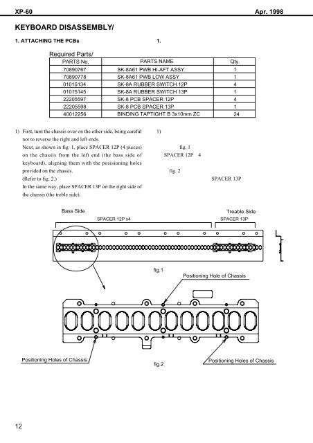
XP-60 Apr. 1998<br />
KEYBOARD DISASSEMBLY/<br />
1. ATTACHING THE PCBs<br />
1. <br />
Required Parts/<br />
PARTS No, PARTS NAME Qty.<br />
70890767<br />
70890778<br />
01015134<br />
01015145<br />
22205597<br />
22205598<br />
40012256<br />
SK-8A61 PWB HI-AFT ASSY<br />
SK-8A61 PWB LOW ASSY<br />
SK-8A RUBBER SWITCH 12P<br />
SK-8A RUBBER SWITCH 13P<br />
SK-8 PCB SPACER 12P<br />
SK-8 PCB SPACER 13P<br />
BINDING TAPTIGHT B 3x10mm ZC<br />
1<br />
1<br />
4<br />
1<br />
4<br />
1<br />
24<br />
1) First, turn the chassis over on the other side, being careful<br />
not to reverse the right and left ends.<br />
Next, as shown in fig. 1, place SPACER 12P (4 pieces)<br />
on the chassis from the left end (the bass side of<br />
keyboard), aligning them with the posisioning holes<br />
provided on the chassis.<br />
(Refer to fig. 2.)<br />
In the same way, place SPACER 13P on the right side of<br />
the chassis (the treble side).<br />
1) <br />
<br />
fig. 1<br />
SPACER 12P4<br />
<br />
fig. 2<br />
SPACER 13P<br />
<br />
Bass Side<br />
SPACER 12P x4<br />
Treable Side<br />
SPACER 13P<br />
fig.1<br />
Positioning Hole of Chassis<br />
Positioning Holes of Chassis<br />
fig.2<br />
Positioning Holes of Chassis<br />
12