
You also want an ePaper? Increase the reach of your titles
YUMPU automatically turns print PDFs into web optimized ePapers that Google loves.
XP-60 Apr. 1998<br />
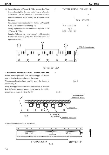
4) Then, tighten the LOW and HI PCBs with the Tap Tight<br />
Screws. First tighten the near-center Screws 1, then the<br />
end Screws 2 on the other side. (This order must be<br />
followd. Ohterwise the PCBs may not be flush with the<br />
Spacers.)<br />
Then tighten the remaining Screws 3 of the LOW and HI<br />
PCBs. (For the above, refer to Fig. 7.)<br />
Finally, tighten the Screws in the area adjacent to the<br />
LOW and HI PCBs.<br />
Since the PCBs may have been warped <strong>by</strong> soldering, etc.,<br />
it is recommended to gently hole down the center and<br />
tighten the Screws.<br />
4) TAP TITE SCREWSPCB LOWHI<br />
<br />
1<br />
2<br />
PCBSPACER<br />
<br />
PCBLOWHI3<br />
fig. 7<br />
PCBLOWHI<br />
<br />
<br />
<br />
2<br />
3<br />
1<br />
PCB Adjacent Area<br />
fig.7 (ex. 32P LOW)<br />
2. REMOVAL AND REINSTALLATION OF THE KEYS<br />
Before removing the keys, first take the stopper off the rear<br />
side of the chassis, then take away the spring.<br />
When reinstalling the keys, carefully apply the stopper as<br />
shown in fig. 8.<br />
Bring the stopper into closs contact with the ends of the white<br />
key shafts and press the stopper in the area of the doublecoated<br />
tape to secure it. (Refer fig. 8.)<br />
2. <br />
<br />
<br />
fig. 8<br />
<br />
<br />
<br />
fig. 8<br />
Double-Coated<br />
Adhesive Tape<br />
Stopper<br />
fig.8<br />
Sharp<br />
Key Axis<br />
Normal Key Axis<br />
Viewed from the rear side of the chassis.<br />
<br />
32P LOW<br />
29P HI<br />
14<br />
STOPPER 12P x4<br />
fig.9<br />
STOPPER 13P