9115 Power Supply Programming Manual - BK Precision
9115 Power Supply Programming Manual - BK Precision
9115 Power Supply Programming Manual - BK Precision

Create successful ePaper yourself
Turn your PDF publications into a flip-book with our unique Google optimized e-Paper software.
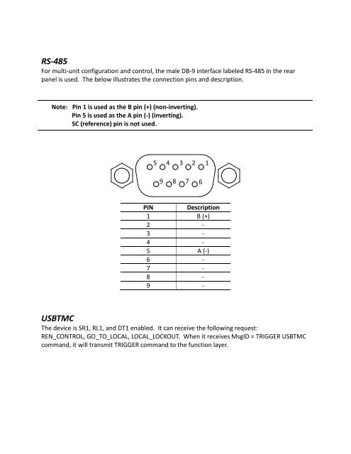
RS-485<br />
For multi-unit configuration and control, the male DB-9 interface labeled RS-485 in the rear<br />
panel is used. The below illustrates the connection pins and description.<br />
Note: Pin 1 is used as the B pin (+) (non-inverting).<br />
Pin 5 is used as the A pin (-) (inverting).<br />
SC (reference) pin is not used.<br />
5<br />
4<br />
3<br />
2<br />
1<br />
9<br />
8<br />
7<br />
6<br />
PIN<br />
Description<br />
1 B (+)<br />
2 -<br />
3 -<br />
4 -<br />
5 A (-)<br />
6 -<br />
7 -<br />
8 -<br />
9 -<br />
USBTMC<br />
The device is SR1, RL1, and DT1 enabled. It can receive the following request:<br />
REN_CONTROL, GO_TO_LOCAL, LOCAL_LOCKOUT. When it receives MsgID = TRIGGER USBTMC<br />
command, it will transmit TRIGGER command to the function layer.