9115 Power Supply Programming Manual - BK Precision
9115 Power Supply Programming Manual - BK Precision
9115 Power Supply Programming Manual - BK Precision

You also want an ePaper? Increase the reach of your titles
YUMPU automatically turns print PDFs into web optimized ePapers that Google loves.
Model: <strong>9115</strong><br />
Multi-Range DC <strong>Power</strong> <strong>Supply</strong><br />
PROGRAMMING MANUAL
Table of Contents<br />
1 Remote Operation ........................................................................................ 4<br />
1.1 Interface Connection ........................................................................................................ 4<br />
RS-232 ..................................................................................................................................... 4<br />
GPIB ......................................................................................................................................... 4<br />
RS-485 ..................................................................................................................................... 5<br />
USBTMC ................................................................................................................................... 5<br />
2 Remote Commands ...................................................................................... 6<br />
2.1 IEEE488.2 Common Commands ....................................................................................... 6<br />
2.2 STATUS Subsystem ............................................................................................................ 8<br />
2.3 SYSTEM Subsystem ......................................................................................................... 12<br />
2.4 TRIGGER Subsystem ....................................................................................................... 15<br />
2.5 SOURCE Subsystem ........................................................................................................ 15<br />
2.6 MEASUREMENT Commands ........................................................................................... 18<br />
2.7 LIST AND SEQUENCE Commands ................................................................................... 20
1 Remote Operation<br />
1.1 Interface Connection<br />
RS-232<br />
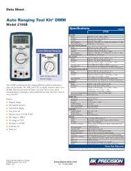
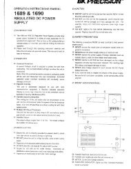
For RS-232 connectivity, refer to the diagram below for pin out information. The RS-232 is<br />
labeled in the rear panel and it is a female DB-9 interface.<br />
5<br />
4<br />
3<br />
2<br />
1<br />
9<br />
8<br />
7<br />
6<br />
PIN<br />
Description<br />
1 -<br />
2 Transmit Data<br />
3 Receive Data<br />
4 -<br />
5 GND<br />
6 -<br />
7 -<br />
8 -<br />
9 -<br />
A straight pin-to-pin DB9 female to DB9 male serial cable is required for using the RS-232<br />
interface. Do not use a null modem or crossover DB9 serial cable.<br />
Refer to the user manual for details on configuring all serial settings as required for RS-232<br />
communication.<br />
GPIB<br />
The power supply can be configured with a GPIB address from 0 – 31. To communicate via GPIB,<br />
connect a GPIB cable to the GPIB interface on the rear panel, as illustrated below.
RS-485<br />
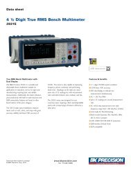
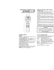
For multi-unit configuration and control, the male DB-9 interface labeled RS-485 in the rear<br />
panel is used. The below illustrates the connection pins and description.<br />
Note: Pin 1 is used as the B pin (+) (non-inverting).<br />
Pin 5 is used as the A pin (-) (inverting).<br />
SC (reference) pin is not used.<br />
5<br />
4<br />
3<br />
2<br />
1<br />
9<br />
8<br />
7<br />
6<br />
PIN<br />
Description<br />
1 B (+)<br />
2 -<br />
3 -<br />
4 -<br />
5 A (-)<br />
6 -<br />
7 -<br />
8 -<br />
9 -<br />
USBTMC<br />
The device is SR1, RL1, and DT1 enabled. It can receive the following request:<br />
REN_CONTROL, GO_TO_LOCAL, LOCAL_LOCKOUT. When it receives MsgID = TRIGGER USBTMC<br />
command, it will transmit TRIGGER command to the function layer.
2 Remote Commands<br />
2.1 IEEE488.2 Common Commands<br />
Here’s a list and description of all common SCPI commands supported by the instrument.<br />
*CLS<br />
This command clears the following registers.<br />
Standard event register<br />
Query event register<br />
Operation event register<br />
Status byte register<br />
Error code<br />
Command syntax: *CLS<br />
Parameter: None<br />
*ESE<br />
This command can set the parameter of standard event enable register. Setting parameter can<br />
determine which bit of standard event register is 1 and the byte will enable ESB of status byte<br />
register as 1.<br />
Command syntax: *ESE <br />
Parameter: 0~255<br />
The value when power on: Refer to *PSC command<br />
Example: *ESE 128<br />
Query syntax: *ESE?<br />
Returned parameter: <br />
The bit definition of the standard event enabled register:<br />
Bit 7 6 5 4 3 2 1 0<br />
Position<br />
Bit Name PON Not CME EXE DDE QYE Not OPC<br />
used<br />
used<br />
Bit Weight 128 32 16 8 4 1<br />
PON <strong>Power</strong>-on<br />
CME Command error<br />
EXE Execution error<br />
DDE Device-dependent error<br />
QYE Query error<br />
OPC Operation complete
*ESR?<br />
This command can read the value of standard event status register. After executing this<br />
command, standard event status register is reset. Bit definition of standard event status register<br />
is the same as the standard event status enable register.<br />
Query syntax: *ESR?<br />
Parameter: None<br />
Returned parameter: <br />
*IDN?<br />
This command can read information about power supply. The returns parameter contains 4<br />
segments divided by comma.<br />
Query syntax: *IDN?<br />
Parameter: None<br />
Returned parameter: segment description<br />
B&K <strong>Precision</strong> Manufacturer<br />
<strong>9115</strong> Product model<br />
XXXXXX Product serial number<br />
VX.XX –VX.XX Software version<br />
Example: B&K <strong>Precision</strong>, <strong>9115</strong>, 00000000000004, V1.01-V1.00<br />
*OPC<br />
When all commands before this command are executed, bit OPC in standard event register will<br />
be set to 1.<br />
Command syntax: *OPC<br />
Parameter: None<br />
Query syntax: *OPC?<br />
Returned parameter: <br />
*RST<br />
This command resets the power supply to default settings.<br />
Command syntax: *RST<br />
Parameter: None<br />
*SRE<br />
This command can set the parameter of state byte enable register. Setting parameter can<br />
determine which byte value of state byte register is 1 and the byte will set RQS of state byte<br />
register to 1. Bit definition of state byte enable register is the same as the state byte register.<br />
Command syntax: *SRE <br />
Parameter: 0~255<br />
Query syntax: *SRE?<br />
Returned parameter: <br />
*STB?<br />
This command can read the data from status byte register.
Query syntax: *STB?<br />
Parameter: None<br />
Returned parameter: <br />
*TRG<br />
When power supply trigger source is a command from via BUS, this command will give a trigger<br />
signal. And its function is the same as “TRIGger” command.<br />
Query syntax: *TRG<br />
Parameter: None<br />
Returned parameter: None<br />
*SAV<br />
This command can save the current setups of power supply to specified memory. These setups<br />
contain current setups, voltage setups, max voltage set, min voltage set, OVP set, OVP timer,<br />
OPP set, voltage rise and fall time, analog interface and series/parallel setting.<br />
The memory is divided into 10 groups, each contain 0~9 (10 total) setups. Up to 100 setups can<br />
be saved in total.<br />
Command syntax: *SAV<br />
Parameter: 0~9<br />
*RCL<br />
This command can recall the setups you saved previously from the specified memory location.<br />
Command syntax: *RCL<br />
Parameter: 0~9<br />
2.2 STATUS Subsystem<br />
You can get the current status of the power supply by reading the operation status registers. The<br />
power supply records the different status of the instrument through the four status register<br />
group. The four status register groups are: status byte register, standard event register, query<br />
status register and operation status register. Status byte register records the information of the<br />
other status registers.<br />
0<br />
3<br />
4<br />
5<br />
BIT Signal Meaning<br />
CAL<br />
WTG<br />
CV<br />
CC<br />
0 OV<br />
Operation status register<br />
The power supply is calculating the new calibration parameter.<br />
The power supply is waiting for the trigger information.<br />
The power supply is in constant voltage status.<br />
The power supply is in constant current status.<br />
Query status register<br />
Over voltage
1<br />
3<br />
4<br />
0<br />
2<br />
3<br />
4<br />
5<br />
7<br />
2<br />
3<br />
4<br />
5<br />
6<br />
7<br />
OC<br />
OP<br />
OT<br />
OPC<br />
QYE<br />
DDE<br />
EXE<br />
CME<br />
PON<br />
EAV<br />
QUES<br />
MAV<br />
ESB<br />
RQS<br />
OPER<br />
Over current<br />
Over power<br />
Over temperature<br />
Standard event register<br />
Operation completed. All the parallel operations are completed.<br />
Query error. Output buffer data lost.<br />
Instrument memory data loss or self test error<br />
Execute error. Command parameter over flow or the operation condition is<br />
not consistent<br />
Command error. There is syntax or semantic error in the command received.<br />
<strong>Power</strong> on bit, this bit is set to 1 after power on<br />
Status byte register<br />
Error buffer available<br />
This bit is set to 1 when any one status of enabled query status register<br />
changes.<br />
Output buffer available<br />
Bit ESB is set to 1 when the status of a enabled standard event status register<br />
changes<br />
If the status of enabled operation register changes, then this bit is set to1.<br />
STATUS Subsystem<br />
STATus:QUEStionable[:EVENt]?<br />
This command can be used to read the value in query event register. After executing this<br />
command, the query event register will be cleared.<br />
Query syntax: STATus:QUEStionable[:EVENt]?<br />
Parameter: None<br />
Returned parameter: <br />
Relative command: STATus:QUEStionable:ENABle<br />
The bit definition of query event enable register:<br />
Bit 15 14 13 12 11 10 9 8<br />
Position<br />
Bit Name<br />
Bit Weight<br />
Not<br />
used<br />
Not<br />
used<br />
Not<br />
used<br />
Not<br />
used<br />
Not<br />
used<br />
Not<br />
used<br />
Not<br />
used<br />
Bit 7 6 5 4 3 2 1 0<br />
Position<br />
Bit Name Not Not Not OT OP Not OC OV<br />
used used used<br />
used<br />
Bit Weight 16 8 2 1<br />
Not<br />
used
STATus:QUEStionable:CONDition?<br />
This command is used to read the value of query condition register. When a bit of QUES<br />
condition changes, the bit value corresponding in QUEST event register is 1.<br />
Query syntax:STATus:QUEStionable: CONDition?<br />
Parameter: None<br />
Returned parameter: <br />
STATus:QUEStionable:ENABle<br />
This command can set the parameter of quest event enable register. Setting parameter can<br />
determine which bit value of quest event register is 1 and the bit will enable QUES.<br />
Command syntax:STATus:QUEStionable:ENABle <br />
Parameter: 0~65535<br />
Default set: Refer to *PSC command<br />
Example: STATus:QUEStionable:ENABle 128<br />
Query syntax: STATus:QUEStionable:ENABle?<br />
Returned parameter: <br />
STATus: QUEStionable:NTRansition<br />
This command is used to edit the negative transition trigger register of operation event. The<br />
parameter determines which bits of operation event register is 1 and will change the OPER of<br />
status byte register to be 1.<br />
Command syntax: STATus: QUEStionable:NTRansition <br />
Parameter: 0~255<br />
Example: STATus: QUEStionable:NTRansition 128<br />
Query syntax: STATus: QUEStionable:NTRansition?<br />
STATus: QUEStionable:PTRansition<br />
This command is used to edit the positive transition trigger register of operation event. The<br />
parameter determines which bits of operation event register is 1 and will change the OPER of<br />
status byte register to be 1.<br />
Command syntax: STATus: QUEStionable:PTRansition <br />
Parameter: 0~255<br />
Example: STATus: QUEStionable:PTRansition 128<br />
Query syntax: STATus: QUEStionable:PTRansition?<br />
STATus:OPERation[:EVENt]?<br />
This command can read the parameter from operation event register. After executing this order,<br />
operation event register is reset.<br />
Query syntax: STATus:OPERation [:EVENt]?<br />
Parameter: None<br />
Returned parameter: <br />
Relative command: STATus: OPERation:ENABle<br />
Bit definition of operation event register:
Bit<br />
Position<br />
Bit Name<br />
Bit<br />
Weight<br />
7 6 5 4 3 2 1 0<br />
Not<br />
used<br />
Not<br />
used<br />
CV CC WTG Not Not CAL<br />
used used<br />
32 16 4 1<br />
STATus:OPERation:CONDition?<br />
This command can read the parameter from the operation condition register. When the<br />
parameter of operation condition register changes, the bit corresponding in operation event<br />
register is 1.<br />
Query syntax: STATus: OPERation: CONDition?<br />
Parameter: None<br />
Returned parameter: <br />
STATus:OPERation:ENABle<br />
This command can set the parameter of operation event enable register. Setting parameter can<br />
determine which bit value of operation event register is 1 and the bit will change OPER of status<br />
byte register to be 1.<br />
Command syntax: STATus: OPERation:ENABle <br />
Parameter: 0~255<br />
Example: STATus: OPERation:ENABle 128<br />
Query syntax: STATus: OPERation:ENABle?<br />
Returned parameter: <br />
STATus:OPERation:NTRansition<br />
This command is used to edit the negative transition trigger register of operation event. The<br />
parameter determines which bits in operation event register is 1 and will change the OPER bit<br />
of status byte register to be set to 1.<br />
Command syntax: STATus:OPERation:NTRansition <br />
Parameter: 0~255<br />
Example: STATus:OPERation:NTRansition 128<br />
Query syntax: STATus:OPERation:NTRansition?<br />
STATus:OPERation:PTRansition<br />
This command edits the positive transition trigger register of operation event. The parameter<br />
determines which bits of operation event register is 1 and will change the OPER bit of status<br />
byte register to be set to 1.<br />
Command syntax: STATus:OPERation:PTRansition <br />
Parameter: 0~255<br />
Example: STATus:OPERation:PTRansition 128<br />
Query syntax: STATus:OPERation:PTRansition?
2.3 SYSTEM Subsystem<br />
SYSTem:ERRor?<br />
This command is used to read the error code and the error information.<br />
Command syntax: SYST:ERR?<br />
Parameter: None<br />
Returned parameter: ,<br />
The following is the error code and the definition:<br />
(101) Too many numeric suffices<br />
(110) No input command<br />
(114) Invalid Numeric suffix<br />
(116) Invalid value<br />
(117) Invalid dimensions<br />
(120) Parameter overflowed<br />
(130) Wrong units for parameter<br />
(140) Wrong type of parameter<br />
(150) Wrong number of parameter<br />
(160) Unmatched quotation mark<br />
(165) Unmatched bracket<br />
(170) Invalid command<br />
(180) No entry in list<br />
(190) Too many dimensions<br />
(191) Too many char<br />
(-200) Execution error<br />
(-221) Settings conflict<br />
(-222) Data out of range<br />
(-223) Too much data<br />
(-224) Illegal parameter value<br />
(-225) Out of memory<br />
(-230) Data Corrupt or Stale<br />
(-270) Macro error<br />
(-310) System error<br />
(-350) Too many errors<br />
(-400) Query error<br />
(-410) Query INTERRUPTED<br />
(-420) Query UNTERMINATED<br />
(-430) Query DEADLOCKED<br />
(-440) Query UNTERMINATED<br />
(0) No error<br />
(1) Module Initialization Lost<br />
(2) Mainframe Initialization Lost<br />
(3) Module Calibration Lost
(4) Eeprom failure<br />
(5) RST checksum failed<br />
(10) RAM selftest failed<br />
(40) Flash write failed<br />
(41) Flash erase failed<br />
(213) RS-232 buffer overrun<br />
(216) RS-232 receiver framing<br />
(217) RS-232 receiver parity<br />
(218) RS-232 receiver overrun<br />
(220) Front panel uart overrun<br />
(221) Front panel uart framing<br />
(222) Front panel uart parity<br />
(223) Front panel buffer overrun<br />
(224) Front panel timeout<br />
(225) Front Crc Check error<br />
(226) Front Cmd Error<br />
(401) CAL switch prevents<br />
(402) CAL password is incorrect<br />
(403) CAL not enabled<br />
(404) readback cal are incorrect<br />
(405) programming cal are incorrect<br />
(406) Incorrect sequence of cal<br />
(600) FETCH of data was not acquired<br />
(601) Measurement overrange<br />
SYSTem:VERSion?<br />
This command is used to query the current SCPI version. The returned parameter is a string<br />
like”YYYY.V”, in which the YYYY is the year of that version, V is the software version of that year.<br />
Command syntax: SYST:VERS?<br />
Parameter: None<br />
Returned parameter: <br />
SYSTem:REMote<br />
This command is used to switch to the remote control mode (PC control).<br />
Parameter: None<br />
SYSTem:LOCal<br />
This command is used to switch the instrument to local control mode (front panel control).<br />
Command syntax: SYST:LOCal<br />
Parameter: None<br />
SYSTem:RWLock<br />
This command is the same function as SYSTem:REMote, except this command can lock “LOCAL”<br />
button as well. When this command is executed, the “Local” button will be disabled.
Command syntax: SYSTem:RWLock<br />
Parameter: None<br />
SYSTem:POSetup<br />
This command configures the power on state of the instrument.<br />
Command syntax: SYSTem:POSetup RST|SAV0<br />
Parameter: RST|SAV0<br />
Returned parameter: None<br />
Query syntax: SYSTem:POSetup?<br />
SYSTem:POSetup?<br />
Command syntax: SYSTem:POSetup?<br />
Parameter: None<br />
Returned parameter: RST|SAV0<br />
SYSTem:CLEar<br />
This command is used to clear the error codes and information.<br />
Command syntax: SYSTem:CLEar<br />
Parameter: None<br />
Returned parameter: None<br />
SYSTem:BEEPer<br />
This command is used to enable or disable the beeper.<br />
Command syntax: SYSTem:BEEPer<br />
Command syntax: SYSTem:BEEPer<br />
Parameters: 0|1|ON|OFF<br />
Query syntax: SYSTem:BEEPer?<br />
Returned value 0 corresponds to the off state of beeper.<br />
Returned value 1 corresponding to the on state of beeper.<br />
Return parameters:0|1<br />
SYSTem:COMMunicate:GPIB:RDEVice:ADDRess<br />
This command is used to set the GPIB address.<br />
Command syntax:SYSTem:COMMunicate:GPIB:RDEVice:ADDRess <br />
Paramters: 0-31<br />
inquiry syntax: SYSTem:COMMunicate:GPIB:RDEVice:ADDRess?<br />
Return parameters: <br />
SYSTem:INTerface<br />
This command is used to select the communication interfaces.<br />
Command syntax:SYSTem:INTerface <br />
ADDRess
This command is used to set the slave machine’s address when communicating through RS485<br />
interface.<br />
Command syntax: ADDRess <br />
Parameters: 0-31<br />
2.4 TRIGGER Subsystem<br />
TRIGger[:IMMediate]<br />
This command is used to create a trigger signal. It will give a trigger signal in BUS trigger source<br />
mode. The function is the same as command *TRG.<br />
Command syntax: TRIGger[:IMMediate]<br />
Parameter: None<br />
Related commands: *TRG<br />
TRIGger:SOURce<br />
This command is used to select the trigger source. <strong>Power</strong> supply can receive trigger signals<br />
directly from front panel by pushing “Trigger” button or receive from a BUS trigger signal (usin<br />
*TRG command).<br />
Command syntax: TRIG:SOURce <br />
Parameters: MANUAL |BUS<br />
Query syntax: TRIGger:SOURce?<br />
Return parameter: MANUAL |BUS<br />
2.5 SOURCE Subsystem<br />
[SOURce:]OUTPut[:STATe]<br />
This command is used to control the output state of the power supply.<br />
Command syntax: [SOURce:]OUTPut [:STATe] <br />
Parameter: 0|1|ON|OFF<br />
Query syntax: [SOURce:]OUTPut[:STATe]?<br />
Return parameter: 0|1<br />
[SOURce:]RISe[:LEVel]<br />
This command is used to set the voltage rising time of the power supply.<br />
Command syntax: [SOURce:]RISe[:LEVel] <br />
Unit: s<br />
Parameter: 0~65.535<br />
Query syntax: [SOURce:]RISe[:LEVel]?<br />
Return parameter: 0~65.535
[SOURce:]FALL[:LEVel]<br />
This command is used to set the voltage falling time of the power supply.<br />
Command syntax: [SOURce:] FALL [:LEVel] <br />
Unit: s<br />
parameter: 0~65.535<br />
Query syntax: [SOURce:] FALL [:LEVel]?<br />
Return parameter: 0~65.535<br />
[SOURce:]CURRent[:LEVel][:IMMediate][:AMPLitude]<br />
This command is used to set the output current value.<br />
Command syntax: [SOURce:]CURRent[:LEVel][:IMMediate][:AMPLitude] <br />
Parameter: MIN TO MAX|MIN|MAX|DEF<br />
Unit: A |mA |uA<br />
Query syntax: [SOURce:]CURRent[:LEVel][:IMMediate][:AMPLitude]?<br />
Parameter: None<br />
Return parameter: <br />
[SOURce:]CURRent[:LEVel]:TRIGgered[:AMPLitude]{ | MINimum | MAXimum }<br />
This command is used to set a current value to be triggered. This value will be set after the<br />
instrument receives a trigger signal. Sending CURRent command will not impact this<br />
command’s current setting value. Sending a query command will return the original setting<br />
value.<br />
Command syntax: [SOURce:]CURRent[:LEVel]:TRIGgered[:AMPLitude] <br />
Parameter: MIN TO MAX|MIN|MAX|DEF<br />
Unit: A<br />
Query syntax: [SOURce:]CURRent[:LEVel]:TRIGgered[:AMPLitude]?<br />
Return parameter: <br />
[SOURce:]VOLTage[:LEVel][:IMMediate][:AMPLitude]<br />
This command is used to set the output voltage value.<br />
Command syntax: [SOURce:]VOLTage[:LEVel][:IMMediate][:AMPLitude] <br />
Parameters: MIN TO MAX|MIN|MAX|DEF<br />
Unit: V| mV| uV<br />
Query syntax: [SOURce:]VOLTage[:LEVel][:IMMediate][:AMPLitude]?<br />
Parameter: None<br />
Return parameter: <br />
[SOURce:]VOLTage[:LEVel]:TRIGgered[:AMPLitude]{ |MINimum | MAXimum}<br />
This command is used to set a voltage value to be triggered. This value will be set when the<br />
instrument receives a trigger signal. Sending VOLTage command will not impact this command’s<br />
voltage setting value. Sending a query command will return the original setting value.<br />
Command syntax: [SOURce:]VOLTage[:LEVel]:TRIGgered[:AMPLitude] <br />
Parameters: MIN TO MAX|MIN|MAX|DEF
Unit: V| mV| uV<br />
Query syntax: [SOURce:]VOLTage[:LEVel]:TRIGgered[:AMPLitude]?<br />
Return parameter: <br />
[SOURce:]VOLTage:PROTection[:LEVel]<br />
This command is used to set the software-voltage protection value.<br />
Command syntax: [SOURce:] VOLTage:PROTection[:LEVel] <br />
Parameter: MIN TO MAX|MIN|MAX|DEF<br />
Parameters: V |mV| uV<br />
Query syntax: [SOURce:] VOLTage:PROTection[:LEVel]?<br />
Parameters: None<br />
Return parameter: <br />
[SOURce:]VOLTage:PROTection:DELay<br />
This command is used to set the software-voltage protection delay time.<br />
Command syntax: [SOURce:]VOLTage:PROTection:DELay<br />
Parameter: 0.001~0.6<br />
unit: s<br />
Query syntax: [SOURce:]VOLTage:PROTection:DELay?<br />
Parameter: 0.001~0.6<br />
Return parameter:<br />
[SOURce:]VOLTage:PROTection:STATe<br />
This command is used to set the software-voltage protection state.<br />
Command syntax: [SOURce:]VOLTage:PROTection:STATe<br />
Parameter: 0|1|ON|OFF<br />
Query syntax: [SOURce:]VOLTage:PROTection:STATe?<br />
Parameter: None<br />
Return parameter: 0|1<br />
[SOURce:]VOLTage:PROTection:TRIGgered?<br />
This command is used to query the executing state of over voltage protection. If “1”, this<br />
indicates the OVP circuit has been triggered and the OVP state is not cleared. If “0”, the OVP<br />
circuit is not triggered.<br />
Command syntax: [SOURce:]VOLTage:PROTection:TRIGgered?<br />
Return value: 0|1<br />
PROTection:CLEar<br />
This command is used to clear the OVP state. Before sending this command, please increase<br />
the upper limitation of OVP or reeeduce the output voltage.<br />
Note: Please remove the device that tripped this protection and then send the command again.<br />
Command syntax: PROT:CLE<br />
[SOURce:]VOLTage:LIMit[:LEVel]
This command is used to set the lower limitation of the output voltage.<br />
Command syntax: [SOURce:]VOLTage:LIMit[:LEVel] <br />
Parameter: MIN TO MAX|MIN|MAX|DEF<br />
Unit: V| mV| uV<br />
Query syntax: [SOURce:]VOLTage:LIMit[:LEVel]?<br />
Return parameter: <br />
[SOURce:]VOLTage:RANGe<br />
This command is used to set the upper limitation of the output voltage.<br />
Command syntax: [SOURce:]VOLTage:RANGe <br />
Parameter: MIN TO MAX|MIN|MAX|DEF<br />
Unit: V |mV |uV<br />
Query syntax: [SOURce:]VOLTage:RANGe?<br />
Return parameter: <br />
[SOURce:]APPLy {|MIN|MAX} [,{ |MIN|MAX}]<br />
This command combines two commands in one: VOLTage, CURRent. As long as the setting<br />
value is within the range of max current and max voltage, then the output voltage and current<br />
will execute according to the present setting value. APPLy command will only be effective when<br />
the setting values are within the range of the upper limits. If not, an execution error will occur.<br />
MIN and MAX can also be used as parameters. Min will enable the output voltage and current<br />
to be 0. Max will enable the output voltage and current to be the upper limit value.<br />
Command syntax: [SOURce:]APPLy ,<br />
Parameter: MIN~MAX<br />
Unit: V, A<br />
Query syntax: [SOURce:]APPLy?<br />
Return parameter: ,<br />
2.6 MEASUREMENT Commands<br />
MEASure[:SCALar]:VOLTage[:DC]?<br />
This command is used to query the actual output voltage.<br />
Command syntax: MEASure[:SCALar]:VOLTage[:DC]?<br />
Parameter: None<br />
Return parameter: <br />
Return parameter unit: V<br />
Example: MEAS:VOLT?<br />
FETCh:VOLTage?<br />
This command is used to read the voltage to be handled in the sample cache. After sending the<br />
command, the readings will be sent to the computer. This command does not affect the<br />
instrument settings. This command does not trigger a measurement operation, and queries<br />
only the latest available reading. Before reading the new reading, the command returns old
eadings.<br />
Command syntax: FETCh:VOLTage?<br />
Return parameter: <br />
Return parameter unit: V<br />
MEASure[:SCALar]:CURRent[:DC]?<br />
This command is used to read the actual current.<br />
Command syntax: MEASure[:SCALar]:CURRent[:DC]?<br />
Parameter: None<br />
Return parameter: <br />
Return parameter unit: A<br />
example: MEAS:CURR?<br />
FETCh:CURRent?<br />
This command is used to read the current which is in the sample cache. After sending the<br />
command, the readings will be sent to the computer. This command does not affect the<br />
instrument settings. This command does not trigger a measurement operation, and queries<br />
only the latest available reading. Before reading the new reading, the command returns the old<br />
readings.<br />
Command syntax: FETCh:CURRent?<br />
Return parameter: <br />
MEASure[:SCALar]:POWer[:DC]?<br />
This command is used to enquire the actual output power.<br />
Command syntax: MEASure[:SCALar]:POWer[:DC]?<br />
Parameter: None<br />
Return parameter: <br />
Return parameter unit: W<br />
Example: MEAS:POWer?<br />
FETCh:POWer?<br />
This command is used to read the power which is in the sample cache. After sending the<br />
command, the readings will be sent to the computer. This command does not affect the<br />
instrument settings. This command does not trigger a measurement operation, and queries<br />
only the latest available reading. Before reading the new reading, the command returns the old<br />
readings.<br />
Command syntax: FETCh:POWer?<br />
Return parameter:
2.7 LIST AND SEQUENCE Commands<br />
LIST Commands<br />
LIST:STATe<br />
This command is used to set the state of list mode.<br />
Command syntax: LIST:STATe <br />
Query syntax: LIST:STATe?<br />
Return parameter: 0|1<br />
LIST:RECall<br />
This command is used to recall a list file.<br />
Command syntax: LIST:RECall <br />
Parameter: 1~10<br />
Query syntax: LIST:RECall?<br />
Return parameter: 1~10<br />
LIST:EDIT<br />
This command is used to select which list file to edit.<br />
Command syntax: LIST:EDIT <br />
Parameter: 1~10<br />
Query syntax: LIST:EDIT?<br />
Return parameter: 1~10<br />
LIST:POWer<br />
This command is used to edit the power limit of the list file.<br />
Comman syntax:LIST:POWer <br />
Parameter: MIN~MAX<br />
Query syntax: LIST:POWer?<br />
Return parameter: MIN~MAX<br />
LIST:REPeat<br />
This command is used to edit the number of repeat times of the list file.<br />
Command syntax:LIST:REPeat <br />
Parameter: 1~65535<br />
Query syntax: LIST:REPeat?<br />
Return parameter: 1~65535<br />
LIST:LINK:SEQuence<br />
This command is used to edit the list sequence to be linked.<br />
Command syntax: LIST:LINK:SEQuence <br />
Parameter: 0~1023
Query syntax: LIST:LINK:SEQuence?<br />
Return parameter: 0~1023<br />
LIST:SEQuence:REPeat ,<br />
This command is used to edit the running count of sequence which is linked to the List file.<br />
Command syntax: LIST:SEQuence:REPeat,<br />
Parameter: Parameter1 represents the sequence number,parameter2 corresponds to the<br />
running count of the sequence (1~65535).<br />
Query syntax: LIST:SEQuence:REPeat? <br />
Return parameter: 0~65535<br />
LIST:SAVe<br />
This command is used to save the list file in nonvolatile memory.<br />
Command syntax: LIST:SAVe<br />
Parameter: None<br />
SEQUENCE Commands<br />
SEQuence:EDIT<br />
This command is used to select the list sequence to be edited.<br />
Command syntax: SEQuence:EDIT <br />
Parameter: 1~10<br />
Query syntax: SEQuence:EDIT?<br />
Return parameter: 1~10<br />
SEQuence:STEP:ACTive<br />
This command is used to select the steps to be activated of sequence.<br />
Command syntax: SEQuence:STEP:ACTive <br />
Parameter: 0~1023<br />
Query syntax: SEQuence:STEP:ACTive?<br />
Return parameter: 0~1023<br />
SEQuence:VOLTage<br />
This command is used to edit the voltage of specified step of the sequence.<br />
Command syntax: SEQuence:VOLTage ,<br />
Unit: V<br />
parameter: Parameter1 represents the number of step to be edited. Parameter2 is the voltage<br />
(MIN~MAX).<br />
Query syntax: SEQuence:VOLTage? <br />
Return parameter: MIN~MAX<br />
SEQuence:CURRent<br />
This command is used to edit the current of specified step of a sequence file.<br />
Command syntax: SEQuence:CURRent,
Parameter: Parameter1 represents the number of step to be edited.Parameter2 is the current<br />
(MIN~MAX).<br />
Query syntax: SEQuence:CURRent? <br />
Return parameter: MIN~MAX<br />
SEQuence:WIDTh<br />
This command is used to edit the width of specified step of the sequence file .<br />
Command syntax: SEQuence:WIDTh <br />
Parameter: Parameter1 represents the number of steps to be edited.Parameter2 is the time<br />
width (0.001~65.535).<br />
Unit: s<br />
Query syntax: SEQuence: WIDTh? <br />
Return parameter: 0.001~65.535<br />
SEQuence:SLOPe<br />
This command is used to edit the slope of a specified step of the sequence file<br />
Command syntax:SEQuence:SLOPe ,<br />
parameter: Parameter1 represents the number of steps to be edited.Parameter2 is the<br />
slope(0.001~65.535).<br />
unit: s<br />
Query syntax: SEQuence:SLOPe? <br />
Return parameter: 0.001~65.535<br />
SEQuence:SAVe<br />
This command is used to save the sequence file.<br />
Command syntax: SEQuence:SAVe<br />
Parameter:None
22820 Savi Ranch Parkway<br />
Yorba Linda, CA92887<br />
www.bkprecision.com<br />
© 2013, 2014 B&K <strong>Precision</strong> Corp.<br />
V020414