PANTEX Lattice Girders - dywidag uk
PANTEX Lattice Girders - dywidag uk
PANTEX Lattice Girders - dywidag uk
You also want an ePaper? Increase the reach of your titles
YUMPU automatically turns print PDFs into web optimized ePapers that Google loves.
<strong>PANTEX</strong> <strong>Lattice</strong> <strong>Girders</strong>
Contents<br />
Introduction................................................................................................................... 3<br />
Fields of Application...................................................................................................... 4<br />
Main Advantages........................................................................................................... 4<br />
System Description....................................................................................................... 4<br />
System Components..................................................................................................... 5<br />
Specifications................................................................................................................ 5<br />
Accessories................................................................................................................... 6<br />
Further References........................................................................................................ 6<br />
Introduction<br />
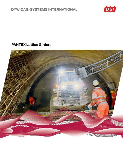
<strong>PANTEX</strong> <strong>Lattice</strong> <strong>Girders</strong> have been<br />
developed for special demands in the<br />
field of Tunneling. The <strong>PANTEX</strong> system<br />
has been extensively tested and used<br />
successfully for numerous tunnel projects<br />
throughout the world.<br />
<strong>PANTEX</strong> <strong>Lattice</strong> <strong>Girders</strong> ensure an<br />
immediate support in the open span area.<br />
Contrary to standard solid-web girders,<br />
<strong>PANTEX</strong> <strong>Lattice</strong> <strong>Girders</strong> are entirely<br />
integrated in the shotcrete lining; porous<br />
zones and shotcrete spray shadows are<br />
avoided.<br />
The load-bearing capacity of <strong>PANTEX</strong><br />
<strong>Lattice</strong> <strong>Girders</strong> has been investigated with<br />
various loading tests and by numerical<br />
analysis. Flexibility regarding geometry<br />
and bearing capacity characterizes this<br />
passive support system for underground<br />
applications.<br />
3
x<br />
S 2<br />
e<br />
S 1<br />
Fields of Application<br />
H<br />
H 1<br />
■■<br />
Passive support system for the<br />
excavated cross section<br />
■■<br />
Profile template for the excavation<br />
geometry<br />
■■<br />
Bearing for pre-support elements<br />
Bar S2<br />
B<br />
y<br />
S 3<br />
Stiffener (spider)<br />
Main Advantages<br />
■■<br />
Immediate support in the excavation<br />
area<br />
Bar S3<br />
■■<br />
Utilization as a true-to-form template<br />
for shotcrete application<br />
■■<br />
Easy and quick assembling,<br />
simple handling<br />
■■<br />
Optimum bond and interconnection<br />
with the shotcrete lining<br />
■■<br />
Simple adjustment and shaping to<br />
the excavation geometry<br />
■■<br />
Ideal bearing for spiles and lagging<br />
boards<br />
■■<br />
Spiles may be installed both above<br />
or through the lattice girders<br />
System Description<br />
■■<br />
Load-bearing elements according to<br />
the particular demands in Tunneling<br />
■■<br />
Spatial 3 or 4 bar girder construction,<br />
connected via stiffening elements<br />
■■<br />
3-bar girder: single bar either at the<br />
excavation or ground side, depending<br />
on the application<br />
■■<br />
4-bar girder: application as wallplate<br />
beam or stiff cross girder<br />
■■<br />
Reduction of girder buckling lengths<br />
by stiffeners<br />
■■<br />
Assembly of the full girder profile by<br />
connecting single girder elements<br />
■■<br />
Load transmission even before<br />
shotcrete application<br />
■■<br />
Integral part of the shotcrete lining<br />
reinforcement<br />
■■<br />
Proven bond according to the design<br />
principles of reinforced concrete<br />
4
System Components<br />
Girder Bars<br />
■■<br />
3-bar girders: 2 + 1 bars<br />
■■<br />
4-bar girders: 2 + 2 bars<br />
■■<br />
Smooth or ribbed reinforcing steel<br />
B 500 B (DIN 488-1) or<br />
B 550 B (ÖNORM B 4707)<br />
■■<br />
High strength and great deformability<br />
Stiffeners<br />
■■<br />
Smooth or ribbed reinforcing steel<br />
■■<br />
Steel grade B 500 B or higher<br />
■■<br />
4 bar stiffeners in one part ensure<br />
optimum bearing capacity<br />
Connections<br />
■■<br />
Angle or alternative flat steel<br />
connection plates<br />
■■<br />
Steel grade S 235 (EN 10025-2)<br />
or higher<br />
■■<br />
Bolts: standard grade 8.8<br />
(EN ISO 898-1)<br />
■■<br />
Slotted bolt or customized<br />
connections available on request<br />
■■<br />
Base plates: standard or elephant<br />
foot version<br />
■■<br />
Special connections available on<br />
request<br />
x<br />
S 2<br />
e<br />
S 1<br />
H<br />
H 1<br />
S 3<br />
y<br />
Specifications<br />
3-bar girder<br />
Gurtstab S2<br />
B<br />
Aussteifungselement (Spinne)<br />
No. Designation 1) H1 S1 S2 S3 Weight 2) H B A W 3) x I x Article No. 4)<br />
[#] [PS1-S3-S2] [mm] [mm] [mm] [mm] [kg/m] [mm] [mm] [cm²] [cm³] [cm 4 ] [–]<br />
1 P50-20-25<br />
25 20 10.2 95<br />
11.19 28 148 14102025XXXX<br />
2 P50-20-30 30 20 11.9 100 13.35 38 193 14102030XXXX<br />
3 P50-20-36 36 20 14.3 106 16.46 42 246 14102036XXXX<br />
50 10<br />
100<br />
4 P50-25-30 30 25 14.7 105 16.89 42 255 14102530XXXX<br />
5 P50-25-36 36 25 17.1 111 20.00 58 336 14102536XXXX<br />
6 P50-30-36 36 30 20.5 116 24.32 64 424 14103036XXXX<br />
7 P70-20-25<br />
25 20 10.4 115<br />
11.19 37 239 14122025XXXX<br />
8 P70-20-30 30 20 12.1 120 13.35 51 306 14122030XXXX<br />
9 P70-20-36 36 20 14.5 126 16.46 54 383 14122036XXXX<br />
70 10<br />
140<br />
10 P70-25-30 30 25 14.9 125 16.89 56 398 14122530XXXX<br />
11 P70-25-36 36 25 17.3 131 20.00 77 517 14122536XXXX<br />
12 P70-30-36 36 30 20.7 136 24.32 83 644 14123036XXXX<br />
13 P95-20-25<br />
25 20 10.8 140<br />
11.19 49 384 14142025XXXX<br />
14 P95-20-30 30 20 12.5 145 13.35 66 485 14142030XXXX<br />
15 P95-20-36 36 20 14.9 151 16.46 69 598 14142036XXXX<br />
95 10<br />
180<br />
16 P95-25-30 30 25 15.3 150 16.89 72 625 14142530XXXX<br />
17 P95-25-36 36 25 17.7 156 20.00 100 799<br />
30 - 50<br />
14142536XXXX<br />
18 P95-30-36 36 30 21.1 161 24.32 107 986 14143036XXXX<br />
19 P115-20-25<br />
25 20 11.0 160<br />
11.19 58 525 14162025XXXX<br />
20 P115-20-30 30 20 12.7 165 13.35 78 658 14162030XXXX<br />
21 P115-20-36 36 20 15.1 171 16.46 82 804 14162036XXXX<br />
115 12<br />
220<br />
22 P115-25-30 30 25 15.5 170 16.89 86 842 14162530XXXX<br />
23 P115-25-36 36 25 17.9 176 20.00 120 1,070 14162536XXXX<br />
24 P115-30-36 36 30 21.3 181 24.32 126 1,312 14163036XXXX<br />
25 P130-20-25<br />
25 20 11.2 175<br />
11.19 66 644 14182025XXXX<br />
26 P130-20-30 30 20 12.9 180 13.35 87 805 14182030XXXX<br />
27 P130-20-36 36 20 15.3 186 16.46 91 980 14182036XXXX<br />
130 12<br />
220<br />
28 P130-25-30 30 25 15.7 185 16.89 96 1,027 14182530XXXX<br />
29 P130-25-36 36 25 18.1 191 20.00 134 1,299 14182536XXXX<br />
30 P130-30-36 36 30 21.5 196 24.32 141 1,589 14183036XXXX<br />
1) Designation: PH1-S3-S2, e.g. P130-20-30 ; 2) Weight including stiffeners (average values)<br />
3) Quotient moment of inertia and maximum distance from the neutral axis to the outer fiber ; 4) ”XXXX” … project-specific designation<br />
Gurtstab S3<br />
5
H<br />
H1<br />
4-bar girder<br />
No. Designation 1) H1 S1 S2 Weight 2) H B A W 4) x W 4) y Article No. 3)<br />
[#] [PH1-S2] [mm] [mm] [mm] [kg/m] [mm] [mm] [cm²] [cm 3 ] [cm 3 ] [–]<br />
1 P100-20<br />
20 12.7 140 12.57 65 41 14200020XXXX<br />
2 P100-25 25 14.3 150 19.63 103 56 14200025XXXX<br />
50 10<br />
100<br />
3 P100-30 30 19.4 160 28.27 151 72 14200030XXXX<br />
4 P100-36 36 26.7 172 40.72 222 88 14200036XXXX<br />
5 P140-20<br />
20 13.1 190 12.57 96 65 14220020XXXX<br />
6 P140-25 25 18.5 200 19.63 151 94 14220025XXXX<br />
75 10<br />
140<br />
7 P140-30 30 25.3 210 28.27 219 124 14220030XXXX<br />
8 P140-36 36 35.1 222 40.72 319 161 14220036XXXX<br />
9 P190-20<br />
20 13.9 230 12.57 121 90 14240020XXXX<br />
10 P190-25 25 19,3 240 19.63 190 132 14240025XXXX<br />
95 10<br />
180<br />
11 P190-30 30 26.1 250 28.27 275 178 14240030XXXX<br />
12 P190-36 36 35.9 262 40.72 399 237 14240036XXXX<br />
13 P230-20<br />
20 14.3 270 12.57 146 114 14260020XXXX<br />
14 P230-25 25 19.7 280 19.63 228 170 14260025XXXX<br />
115 10<br />
220<br />
15 P230-30 30 26.5 290 28.27 330 233 14260030XXXX<br />
16 P230-36 36 36.3 302 40.72 479 316 14260036XXXX<br />
17 P260-20<br />
20 14.7 300 12.57 164 114 14280020XXXX<br />
18 P260-25 25 20.1 310 19.63 258 170 14280025XXXX<br />
130 10<br />
220<br />
19 P260-30 30 26.9 320 28.27 372 233 14280030XXXX<br />
20 P260-36 36 36.7 332 40.72 539 316 14280036XXXX<br />
Gurtstab S2<br />
B<br />
y<br />
S1<br />
x<br />
Ausste<br />
1) Designation: PH1-S2, e.g. P140-30<br />
2) Weight including stiffeners (average values)<br />
3) ”XXXX” … project-specific designation<br />
4) Quotient moment of inertia and maximum distance between outer fiber and neutral axis<br />
Accessories<br />
Angle connection plates and base plates<br />
Gurtstab S2<br />
Wallplate beams<br />
Type Angle Connections Foot Plates<br />
Designation<br />
Angle steel<br />
(B x L x t) 1) Cut length G 2) Size<br />
(B x L x t)<br />
G<br />
[PH1] [mm] [mm] [kg] [mm] [kg]<br />
P50<br />
110<br />
1.7<br />
1.7<br />
100 x 100 x 10 0.8<br />
P70 138<br />
2.1<br />
2.1<br />
2.1<br />
140 x 140 x 10 1.6<br />
2.5<br />
P95 165<br />
2.5 145 x 180 x 10 2.1<br />
80 x 120 x 10<br />
2.5<br />
3.0<br />
P115 200<br />
3.0<br />
3.0<br />
165 x 220 x 10 2.9<br />
P130 210<br />
3.2<br />
3.2<br />
3.2<br />
180 x 220 x 10 3.2<br />
1) Cut with 60° miter, weight: 15 [kg/m]<br />
2) Weight per single angle - angle connections consists of 4 angle plates<br />
Further References<br />
■■<br />
Ongoing internal factory production<br />
control<br />
■■<br />
External supervision of the<br />
manufacturing process<br />
■■<br />
Certificate of conformity No.<br />
11 7165-1/1, MPA NRW (Germany),<br />
dating 2012-05-24, for the building<br />
product DSI lattice girders type<br />
<strong>PANTEX</strong> / 3 bars<br />
DSI Austria, Alfred-Wagner-Straße 1, A-4061 Pasching/Linz<br />
Phone: +43-7229-61049-0 E-Mail: office@<strong>dywidag</strong>-systems.at<br />
■■<br />
Numerical analysis of the static loadbearing<br />
capacity and bending test<br />
reports available on request<br />
Weise mißbräuchlich verwendet werden.<br />
■■<br />
Allowable tightening torques and<br />
I:\50_CAD\1410\141020002002.idw<br />
mounting pre-load for set metrical set<br />
screws: see VDI guideline No. 2230,<br />
sheet 1<br />
Gegenstand der Unterlage / Zeichnung ist unser geistiges<br />
Eigentum. Diese Zeichnung darf ohne unsere vorherige<br />
schriftliche Zustimmung weder vervielfältigt noch Dritten zu<br />
Kenntnis gebracht werden. Sie darf auch nicht in anderer<br />
(Urheberschutzgesetz v. 09.09.1965)<br />
■■<br />
4-bar girders can be used as wallplate<br />
beams for crown drives<br />
■■<br />
Installation of 90° axial rotated 4-bar<br />
girders in the longitudinal direction<br />
■■<br />
Wallplate beams serve as bearing and<br />
profile template for installation of the<br />
girder arch<br />
■■<br />
Bend-proof frontal connection allows<br />
free crown advancing<br />
■■<br />
At the same time, wallplate beams<br />
30 -50<br />
are considered as statically effective<br />
reinforcement for the foot beam<br />
Bearb:<br />
Gepr:<br />
Norm<br />
Gruppe<br />
Datum<br />
Name<br />
DDl<br />
WDk<br />
Ersatz für:<br />
6
EMEA<br />
DYWIDAG-Systems International GmbH<br />
Alfred-Wagner-Strasse 1<br />
4061 Pasching/Linz, Austria<br />
Phone +43-7229-610 49 0<br />
Fax +43-7229-610 49 80<br />
E-mail alwag@<strong>dywidag</strong>-systems.at<br />
www.alwag.com<br />
North America<br />
DSI Underground Systems Inc.<br />
9786 S Prosperity Road<br />
West Jordan, UT 84081, USA<br />
Phone +1-801-973 7169<br />
Fax +1-801-973 7172<br />
E-mail dsiunderground@dsiunderground.com<br />
www.dsiunderground.com<br />
South America<br />
DSI Chile Industrial Ltda.<br />
Las Encinas #1387, Valle Grande<br />
Lampa, Santiago de Chile, Chile<br />
Phone +56-2-596 96 20<br />
Fax +56-2-596 96 69<br />
E-mail informaciones@<strong>dywidag</strong>-systems.cl<br />
www.dsi-chile.com<br />
APAC/ASEAN<br />
DYWIDAG-Systems International Pty. Ltd.<br />
25 Pacific Highway<br />
Bennetts Green, NSW 2290, Australia<br />
Phone +61-2-49 48 90 99<br />
Fax +61-2-49 48 99 56<br />
E-mail dsi@<strong>dywidag</strong>.com.au<br />
www.dsiminingproducts.com/au<br />
Please note:<br />
This brochure serves basic information<br />
purposes only. Technical data and information<br />
provided herein shall be considered<br />
non-binding and may be subject to change<br />
without notice. We do not assume any liability<br />
for losses or damages attributed to the use<br />
of this technical data and any improper<br />
use of our products. Should you require<br />
further information on particular products,<br />
please do not hesitate to contact us.<br />
”ALWAG” (AM 952/79), ”AT” (AM 6138/2003),<br />
”AT-SYSTEM” (AM 6139/2003),<br />
”DYWI ® ” (4197869), ”LSC” (AM 4326/2008),<br />
”OMEGA-BOLT ® ” (3258282),<br />
”POWER SET” (AM 6163/2002), and<br />
”TUBESPILE” (AM 4328/2008) are registered<br />
trademarks of DYWIDAG-Systems International GmbH.<br />
”Combi Coat ® ” and ”CT-Bolt” are trademarks<br />
of Vik Ørsta AS.<br />
DYWIDAG-Systems International GmbH<br />
is a partner of Vik Ørsta AS.<br />
Austria<br />
Argentina<br />
Australia<br />
belgium<br />
Bosnia and herzegovina<br />
Brazil<br />
Canada<br />
Chile<br />
Colombia<br />
Costa Rica<br />
Croatia<br />
Czech republic<br />
Denmark<br />
Egypt<br />
estonia<br />
Finland<br />
France<br />
Germany<br />
Greece<br />
GUATEMALA<br />
HONDURAS<br />
Hong Kong<br />
Indonesia<br />
Italy<br />
Japan<br />
Korea<br />
Lebanon<br />
Luxembourg<br />
Malaysia<br />
Mexico<br />
Netherlands<br />
Norway<br />
Oman<br />
Panama<br />
Paraguay<br />
Peru<br />
POLAND<br />
Portugal<br />
Qatar<br />
Saudi Arabia<br />
singapore<br />
South Africa<br />
Spain<br />
Sweden<br />
Switzerland<br />
Taiwan<br />
Thailand<br />
Turkey<br />
United Arab Emirates<br />
United kingdom<br />
Uruguay<br />
USA<br />
Venezuela<br />
04195-1/04.13-web-he


