Yaesu MD-200A8X
Yaesu MD-200A8X
Yaesu MD-200A8X

Create successful ePaper yourself
Turn your PDF publications into a flip-book with our unique Google optimized e-Paper software.
DYN AMIC MICROPHON E<br />
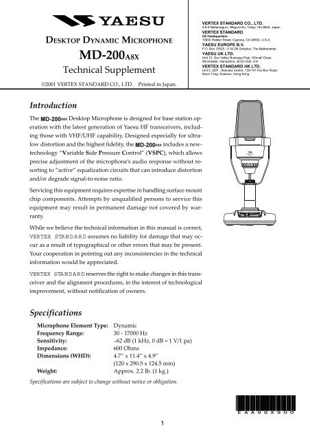
DESKTOP DYNAMIC MICROPHONE<br />
<strong>MD</strong>-<strong>200A8X</strong><br />
Technical Supplement<br />
VERTEX STANDARD CO., LTD.<br />
4-8-8 Nakameguro, Meguro-Ku, Tokyo 153-8644, Japan<br />
VERTEX STANDARD<br />
US Headquarters<br />
10900 Walker Street, Cypress, CA 90630, U.S.A.<br />
YAESU EUROPE B.V.<br />
P.O. Box 75525, 1118 ZN Schiphol, The Netherlands<br />
YAESU UK LTD.<br />
Unit 12, Sun Valley Business Park, Winnall Close<br />
Winchester, Hampshire, SO23 0LB, U.K.<br />
VERTEX STANDARD HK LTD.<br />
Unit 5, 20/F., Seaview Centre, 139-141 Hoi Bun Road,<br />
Kwun Tong, Kowloon, Hong Kong<br />
©2001 VERTEX STANDARD CO., LTD. Printed in Japan.<br />
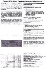
Introduction<br />
The Desktop Microphone is designed for base station operation<br />
with the latest generation of <strong>Yaesu</strong> HF transceivers, including<br />
those with VHF/UHF capability. Designed especially for ultralow<br />
distortion and the highest fidelity, the includes a newtechnology<br />
“Variable Side Pressure Control” (VSPC), which allows<br />
precise adjustment of the microphone’s audio response without resorting<br />
to “active” equalization circuits that can introduce distortion<br />
and/or degrade signal-to-noise ratio.<br />
<strong>MD</strong>-200<br />
Servicing this equipment requires expertise in handling surface mount<br />
chip components. Attempts by unqualified persons to service this<br />
equipment may result in permanent damage not covered by warranty.<br />
While we believe the technical information in this manual is correct,<br />
VERTEX STANDARD assumes no liability for damage that may occur<br />
as a result of typographical or other errors that may be present.<br />
Your cooperation in pointing out any inconsistencies in the technical<br />
information would be appreciated.<br />
VERTEX STANDARD reserves the right to make changes in this transceiver<br />
and the alignment procedures, in the interest of technological<br />
improvement, without notification of owners.<br />
Specifications<br />
Microphone Element Type: Dynamic<br />
Frequency Range:<br />
30 - 17000 Hz<br />
Sensitivity:<br />
–62 dB (1 kHz, 0 dB = 1 V/1 pa)<br />
Impedance:<br />
600 Ohms<br />
Dimensions (WHD): 4.7” x 11.4” x 4.9”<br />
(120 x 290.5 x 124.5 mm)<br />
Weight:<br />
Approx. 2.2 lb. (1 kg.)<br />
Specifications are subject to change without notice or obligation.<br />
EAA98X900<br />
1
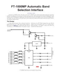
Exploded Views & Mechanical Parts<br />
S8001978<br />
STAND ASSY<br />
S8001981 (X2 pcs)<br />
HEX SOCKET HEAD BOLT<br />
M6X8<br />
S8001979<br />
LOCK KNOB<br />
U41306201 (X4 pcs)<br />
TAPPING SCREW M3X6<br />
S8101120<br />
MAIN PCB<br />
ASSY<br />
S8101121<br />
CORD ASSY<br />
S8001980<br />
STAND COVER ASSY<br />
S8001982 (X5 pcs)<br />
TAPPING SCREW<br />
M3X14<br />
Non-designated parts are available<br />
only as part of a designated assembly.<br />
2
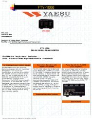
Exploded Views & Mechanical Parts<br />
S8001970<br />
MIC HEAD<br />
ASSY<br />
S8001971<br />
UNIT ASSY (w/o TAPPING SCREW)<br />
U40308201 (X2 pcs)<br />
TAPPING SCREW<br />
3X8<br />
S8001975 (X2 pcs)<br />
RUBBER RING<br />
S8001972<br />
BOTTOM CASE W/CABLE<br />
ASSY<br />
S8001974 (X2 pcs)<br />
SPECIAL SCREW<br />
S8001976<br />
KNOB SCREW<br />
S8001973 (w/o KNOB SCREW)<br />
ARM ASSY<br />
Non-designated parts are available<br />
only as part of a designated assembly.<br />
S8001977<br />
EXTENSION ADAPTER<br />
3
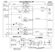
Circuit Diagram<br />
BASE Unit Circuit Diagram<br />
from JP2001<br />
4
Parts Layout<br />
BASE Unit Parts Layout<br />
MIC<br />
GND<br />
a<br />
GND<br />
MIC<br />
a<br />
JP1001<br />
Side A<br />
5
Parts Layout<br />
BASE Unit Parts Layout<br />
Side B<br />
6
Circuit Diagram<br />
LED Unit Circuit Diagram<br />
from MIC<br />
to J1001<br />
LED Unit Parts Layout<br />
Side A<br />
Side B<br />
7
Parts List<br />
REF. DESCRIPTION VALUE V/W TOL. MFR'S DESIG VXSTD P/N LOT. SIDE.<br />
8