Soundcard Isolation Project - VA3CR
Soundcard Isolation Project - VA3CR
Soundcard Isolation Project - VA3CR

Create successful ePaper yourself
Turn your PDF publications into a flip-book with our unique Google optimized e-Paper software.
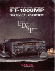
Design and Construction Manual<br />
for an<br />
Isolating Sound Card Interface<br />
for SSB Transceivers<br />
Rx Drive<br />
PTT<br />
Tx Drive<br />
Auto<br />
PTT<br />
On<br />
Off<br />
Isolating<br />
Sound Card Interface<br />
by kk7uq<br />
by Clint Hurd - kk7uq<br />
Discovery Bay Computing<br />
Port Townsend, Washington<br />
Release 1.2<br />
July 6, 2001<br />
i
Table of Contents<br />
1 Introduction 1<br />
1.1 Scope 1<br />
1.2 Intended Use 1<br />
1.3 Copyright & Ownership 1<br />
1.4 Caveats & Disclaimers 1<br />
1.5 Features 1<br />
2 What You Will Need to Build the 3<br />
Interface<br />
2.1 Skills 3<br />
2.2 Tools & Materials 3<br />
3 Theory of Operation 3<br />
3.1 PSK31 Requirements 3<br />
3.1.1 Bandwidth 4<br />
3.1.2 Software Functions 4<br />
3.1.3 SSB Rig Audio Levels 4<br />
3.1.4 PC Sound Card Audio Levels 4<br />
3.1.5 Noise & Feedback 4<br />
3.2 Description of Interface 5<br />
3.2.1 Receive Audio Path 5<br />
3.2.2 Transmit Audio Path 6<br />
3.2.3 PTT 6<br />
3.2.3.1 Control 6<br />
3.2.3.2 Configuration -1 6<br />
3.2.3.3 Configuration -2 7<br />
3.2.3.4 Indicator 7<br />
3.2.3.5 Mode Control Switch 7<br />
3.3 Deciding Which Configuration is 7<br />
Right for your Rig<br />
4 Ordering Parts 9<br />
4.1 Sources 9<br />
4.2 Alternate Sources 9<br />
4.3 Parts List 10<br />
4.3.1 Design and PCB Package 10<br />
4.3.2 Circuit Board Assembly 10<br />
and Serial Port Cable<br />
4.3.3 Additional Components Needed 10<br />
for -1 Option<br />
4.3.4 Audio Cables 11<br />
4.3.5 Rig Control Cables 11<br />
4.3.6 Rig Microphone or 11<br />
Accessory Connector<br />
5 Assembly 12<br />
5.1 PCB Assembly 12<br />
5.1.1 Polarized Components 12<br />
5.1.2 Components Requiring Trim 12<br />
Before Insertion<br />
5.1.3 Order of Assembly 13<br />
5.1.4 Component Stuffing List 13<br />
5.2 Cable Assembly<br />
15<br />
5.2.1 Serial Port Cable 15<br />
5.2.2 SSB Rig Control Cables 16<br />
5.3 Cover Plate 18<br />
5.3.1 Drill Template 18<br />
5.3.2 Panel Overlay 19<br />
5.3.2.1 Overlay Alignment Jig 19<br />
5.4 Enclosure 20<br />
5.4.1 Drill Template 20<br />
5.4.2 Assembly of the Parts 21<br />
5.4.3 Legend Overlay 21<br />
Configuration -1<br />
5.4.4 Legend Overlay 21<br />
Configuration -2<br />
6 Software Sources 22<br />
7 System Setup and Test 24<br />
7.1 Load the Sound Card Program 24<br />
7.2 Hook Up Your Rig 24<br />
7.3 Receive Settings 24<br />
7.4 Transmit Settings 26<br />
7.4.1 PC Tx Level Adjust 26<br />
7.4.1.1 Mute Unused Sources 26<br />
7.4.1.2 Set the Initial PC Audio Level 26<br />
7.4.2 Getting Ready to Transmit 26<br />
7.4.2.1 Reduce the Rig Power Level 26<br />
7.4.2.2 Set the Tx Frequency 26<br />
7.4.2.3 Tx Audio Offset 27<br />
7.4.2.4 Set the Initial Tx Level Controls 27<br />
7.4.2.5 Set the Audio Monitor Level 27<br />
7.4.2.6 Test the PTT 27<br />
7.4.2.7 Power Settings 27<br />
7.4.2.8 Adjust the Mic and Wave Level 28<br />
7.4.3 Your First QSO 28<br />
7.4.3.1 Tune Up Away from Other Stations 28<br />
7.4.3.2 Look for a CQ 28<br />
7.4.3.3 Getting an IMD Report 28<br />
7.4.4 The IMD Report 28<br />
7.5 Common Problems and Their Cures 30<br />
7.5.1 Spurs 30<br />
7.5.2 Hum 30<br />
7.5.3 Wideband Noise 30<br />
7.5.4 Other Strange Audio 31<br />
7.5.5 Break Up of Your Audio 31<br />
7.6 Filtering the Audio Cable 30<br />
ii
1 Introduction<br />
1.1 Scope - This manual describes the design and assembly of an interface between a PC and a SSB rig.<br />
Included in this manual are sections describing the theory of operation of the interface, material list and<br />
parts ordering guidelines, assembly procedures, system setup and testing, and web links to find software<br />
for operating in PSK31, MFSK16, RTTY, SSTV and CW using the sound card in your PC as the signal<br />
processor.<br />
1.2 Intended Use - This design has been created for the amateur radio community to encourage more<br />
hams to enjoy the pleasures of the new sound card digital modes. This design is ideal for ham club<br />
construction projects and for individual hams who likes to build their own equipment. The end result is a<br />
solid interface for use with sound card modes such as PSK31, MFSK16, RTTY, Hellschreiber and SSTV.<br />
1.3 Copyright and Ownership - all material in this manual is copyright (c) 2001, Discovery Bay<br />
Computing. Copies may be made of these materials, for the personal use of licensed radio amateurs. NO<br />
commercial use of the designs may be made without express written consent of Discovery Bay Computing.<br />
1.4 Caveats and Disclaimers- the designs represented in this manual have been tested in on the air<br />
amateur radio operation and are believed to be accurate. Clint Hurd, and Discovery Bay Computing are<br />
not responsible for errors, mistakes or omissions made by others when building from these designs. No<br />
claims are made to the use or application of the principles in these designs or fitness for any particular<br />
purpose. Clint Hurd and Discovery Bay computing are NOT liable for consequential damages resulting<br />
from the use of these designs.<br />
1.5 Features - The main features of this design include:<br />
• Ground paths between the PC and the SSB rig that travel through the interconnecting cables<br />
are completely eliminated through the use of transformers and an opto-isolator.<br />
• Potentiometers are provided on both Rx and Tx to allow easy level adjustment during<br />
operation. Knobs are located on the top of the enclosure for easy adjustment.<br />
• LED provided to show when the PC PTT control line is activated.<br />
• Switch provided to enable/disable automatic PTT, or to force the rig PTT ON for manual<br />
operation and test.<br />
• Design implemented on a PCB to reduce wiring lengths and simplify assembly.<br />
• Packaged in a small enclosure consistent with the reduced size of the modern transceiver.<br />
The enclosure measures 4.1”w x 2.7”d x 1.6” h.<br />
• Templates provided for hole location on the enclosure and top panel.<br />
• Panel label overlays provided for top and rear panel.<br />
• Can be interfaced to either the rig’s microphone/line out or to a single accessory port on the<br />
rig.<br />
• Interface can be configured for solid state drive of PTT or for relay contact closure for use<br />
with older tube type transceivers.<br />
1
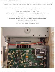
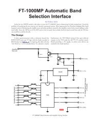
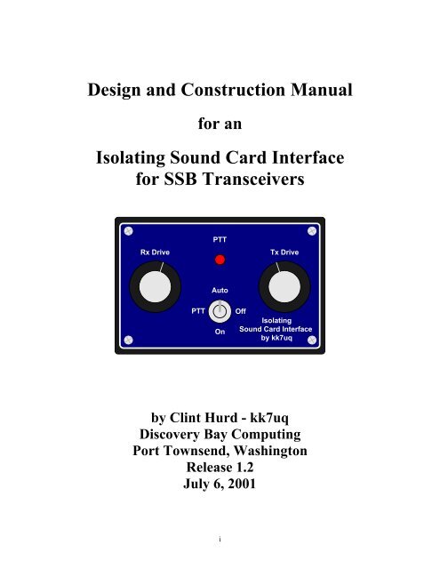
Top view of the control panel of the<br />
Sound Card Interface<br />
The Sound Card Interface with the<br />
top cover removed<br />
2
2 What You Will Need to Build the Interface<br />
2.1 Skills - This design is not a kit, in the normal sense of the term. Rather, it is a homebrew project that<br />
requires basic skills in electronic and mechanical assembly. To be successful at building this project, you<br />
must be able to:<br />
• Identify basic electronic parts<br />
• Order parts from an electronic distributor via a website (or telephone)<br />
• Solder parts to a printed circuit board<br />
• Operate an electric hand drill<br />
• Drill holes in an aluminum plate and in the plastic enclosure using supplied templates.<br />
• Cut and trim holes in a plastic box using the drill and an exacto knife<br />
• Cut and trim overlays and glue them onto the panel<br />
• Measure some voltages and currents with a multi-meter<br />
• Determine the wiring of the microphone input of your SSB rig and build the adapter cable to<br />
connect it to the interface<br />
To simplify the assembly process: templates are provided for drilling the plastic box and the aluminum<br />
cover plate; a printed circuit board is used to mount all electronic parts; printed overlays are used for the<br />
panel and enclosure; a detailed bill of materials is provided for ordering the parts; and a complete assembly<br />
manual is provided.<br />
2.2 Tools and Materials - You will need the following tools and materials<br />
• Needle nosed pliers<br />
• Side cutters<br />
• Phillips screw driver<br />
• Small blade screw driver<br />
• Soldering iron and good quality rosin core solder<br />
• 1/4” electric drill, with bits of 1/16, 5/64, 1/8, 7/32, 1/4, 5/16 & 1/2 inch<br />
• 1/2” counter sink drill bit<br />
• Exacto knife with a new, pointed blade<br />
• Spray on contact cement<br />
• Electronic board cleaner<br />
• Hacksaw or fine toothed craft saw<br />
• Multi-meter<br />
• Scissors<br />
3 Theory of Operation<br />
3.1 PSK31 Requirements - The use of a PC sound card to modulate the audio of a SSB rig has seen<br />
explosive growth in the last few years. In particular, the PSK31 (Phase Shift Keyed, 31 Baud) has changed<br />
the nature of communications over ham radio and attracted thousands of hams to use this as their main<br />
mode of operation. PSK31 is extremely efficient of operating bandwidth use, typically requiring about 60<br />
Hz. Signal separation of 100 Hz without interference is common practice. The nature of the PSK31<br />
modulation system is such that it is effectively a two-tone modulation system. Because of this, good<br />
linearity must be provided throughout the audio path to prevent unwanted side bands from being created by<br />
the system.<br />
3
3.1.1 Bandwidth - To realize this low bandwidth and close signal separation, some care must be taken in<br />
adjustment of the audio drive of the transmitter from the PC, and particular attention must be paid to<br />
minimizing stray signal pickup from sources such as the RF field of the transmitter, AC power lines and<br />
other sources. It is the job of the interface system to provide clean signals to the transmitter in this<br />
potentially hostile environment.<br />
The basic concept is very straight forward. During transmit, audio output from the PC sound card is<br />
provided at the microphone (or accessory port) of the SSB rig. The SSB rig is keyed using the PTT input<br />
to the rig. Data input from the operator is provided by the keyboard to the sound card software. The sound<br />
card software converts it to the modulation format and uses the sound card to create the audio output for<br />
the SSB rig.<br />
During receive, the audio from the SSB rig is connected to the audio input of the PC sound card, and the<br />
sound card software decodes the audio signal and provides text output on the screen.<br />
3.1.2 Software Functions - The software running on the PC provides the functions of:<br />
• Operator Interface - Keyboard and Screen<br />
• Scanning a portion of the audio band (200 to 4000 Hz) and presenting a view of this spectrum<br />
on a waterfall or spectrum display<br />
• Selection of a particular signal, filtering it to separate from other signals and decoding it.<br />
• Presenting the output to the screen.<br />
• When ready to transmit, accepting the data via keyboard and converting the keyboard data to<br />
a modulated audio output to be sent to the SSB rig.<br />
3.1.3 SSB Rig Audio Levels - are consistent with driving speakers or headsets. These signals have an<br />
extremely wide dynamic range: from millivolts to around 5 V p-p. The PC Sound Card accepts levels up<br />
to about 5v p-p. In general, the audio levels from the rig to the sound card are compatible. If signals<br />
approach the maximum range of the sound card input, a warning message from the software will be given<br />
for the operator to reduce the audio level. The receive audio level can be controlled by RF gain of the<br />
receiver, input gain of the sound card, or the RX level control potentiometer in the interface. In practice,<br />
all of these controls are used during setup and operation of the system.<br />
3.1.4 PC Sound Card Audio Levels - The audio levels created from the sound card are in the range of 0.1<br />
to 5 v p-p. Typical signal level is around 1V p-p. The SSB rig, however, expects signals that are<br />
compatible with microphones, i.e. in the tens of millivolts range. The interface must provide some level<br />
reduction to bring the signals to the right scale. The actual level required is a function of the microphone<br />
gain setting of the rig, the audio level of the PC soundcard and the TX level control potentiometer in the<br />
interface. All of these controls are set during the system setup, covered in chapter 6.<br />
3.1.5 Noise & Feedback - One problem with lower level input is that any signal picked up on the transmit<br />
audio wiring can approach the expected signal level, degrading S/N and putting unwanted signals on the<br />
transmitted audio. If the noise source is the RF created by the transmitter, feedback will occur with broad<br />
band noise resulting on the transmitted audio. There are several lines of defense that can be taken to ensure<br />
clean, quiet operation.<br />
• Shield the cables, and provide good ground connections for all components of the system,<br />
including the PC.<br />
• Provide a filter in the interface to remove unwanted RF signals that have been picked up. This<br />
combined with short lead lengths in the cables from the interface to the rig can be very effective.<br />
• Eliminate any ground loop between the components placed along the signal path which may inject<br />
common mode noise into the audio. This is done in the interface by using audio transformers on<br />
4
oth the input and output audio paths. The PTT control is also isolated using opto-isolator<br />
components.<br />
• Select the audio levels along the path to enhance S/N ratio when ever possible. This is covered in<br />
the chapter on system setup.<br />
• Ensure that the audio created by the PC is in fact the ONLY audio created by the sound card<br />
software. Other inputs to the sound card exist, and can be active unless positive steps are taken to<br />
ensure that they are turned off. This is also covered in the chapter on system setup.<br />
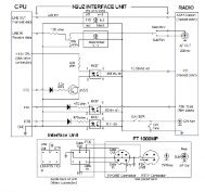
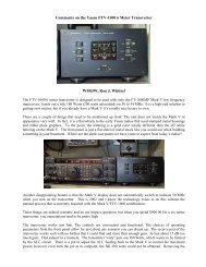
3.2 Description of the Interface - The schematic diagram for the PCB is shown in figure 3.1<br />
below. Sound card or PC functions are shown on the left side of the drawing. SSB rig functions are<br />
shown on the right side of the drawing. Signal flow is indicated by arrows to show the flow from the<br />
source to the destination.<br />
To<br />
Sound Card<br />
Line In<br />
From<br />
Sound Card<br />
Spkr Out<br />
External Cable w/ DB9<br />
female serial port<br />
conn shown for ref.<br />
DTR 4<br />
RTS 7<br />
Gnd 5<br />
Ring<br />
Tip<br />
Sleeve<br />
3.5mm Stereo<br />
Receptacle<br />
3.5mm Stereo<br />
Receptacle<br />
2.5mm Stereo<br />
Receptacle<br />
Rx Drive<br />
1k pot<br />
*** R10 1K<br />
R1 8.2k<br />
R2 100<br />
.0047uF 2<br />
All diodes<br />
1N4148<br />
4N33 Opto Isolator<br />
DTR * D1 * R3<br />
1<br />
5<br />
2.2 k<br />
RTS * D2<br />
2<br />
4<br />
6<br />
n.c.<br />
1:1 600 ohm<br />
Audio Transformer<br />
6<br />
5<br />
4<br />
SW1 - PTT Control<br />
Up - Auto<br />
Ctr - PTT Off<br />
Down - PTT On<br />
Note: all components marked with * are stuffed per Table 1<br />
** are only used if laptop used on config -1, see manual<br />
*** are used for rigs requiring higher audio drive levels, see manual<br />
J2<br />
J3<br />
J1<br />
U1<br />
1<br />
2 3<br />
R6<br />
C3<br />
1<br />
1:1 600 ohm<br />
Audio Transformer<br />
3<br />
Primary<br />
X2<br />
X1<br />
3<br />
Primary<br />
2<br />
6<br />
5<br />
1 4<br />
**R9 2.2 k<br />
* R7 4.7 k<br />
Tx Drive<br />
1k pot<br />
* R4<br />
4.7 k<br />
LED1<br />
SW1 (spdt c.o.)<br />
1 R5<br />
* D3<br />
C1<br />
2<br />
3 1.0 uF<br />
Red LED<br />
'PTT'<br />
3.5mm Stereo<br />
Receptacle<br />
w/ switches<br />
R8<br />
51<br />
A<br />
A<br />
* K1<br />
* D4<br />
Table 1 Component Use Chart for Option -1 or -2<br />
* C2<br />
.0047uF<br />
B<br />
B<br />
D<br />
D<br />
-1 With Relay Use Components J6 K1 R3 D3 C2<br />
-2 W/O Relay Use Components R7 R9 D4 A-A B-B D-D<br />
8<br />
7<br />
J5<br />
4<br />
5<br />
2<br />
1<br />
J4<br />
RJ45<br />
Receptacle<br />
+12 V<br />
Pgnd<br />
From Xcvr<br />
Spkr Out<br />
(Alternate)<br />
From Xcvr<br />
Aux Conn<br />
Line Out<br />
Ret<br />
To Xcvr<br />
Mic. or<br />
Aux Conn<br />
Line In<br />
Ret<br />
To Xcvr<br />
PTT<br />
Ret<br />
J6<br />
* DC Power<br />
Receptacle 2.5mm<br />
x 5.5 mm mounted<br />
on chassis, used<br />
on -1 config only<br />
kk7uq Sound Card Interface Schematic Diagram<br />
Figure 3.1 Sound Card Interface Schematic Diagram<br />
3.2.1 Receive Audio Path - At the top of the page the flow of audio from the rig to the sound card is<br />
shown. There are two possible sources for this audio: a source terminated in an audio connector such as a<br />
3.5mm monoaural source (speaker out, headset out or line out). The other possible source is from an<br />
accessory connector which contains both output audio, input audio, and PTT functions. The interface is<br />
designed to operate with either method of connection. If the 3.5mm audio connector in J4 is used, switches<br />
internal to the connector are used to disconnect the audio from the RJ45 connector (J5). This prevents two<br />
sources from the rig being connected together. During the time that the plug is inserted in the jack, J4, the<br />
5
cable can be momentarily shorted, hence resistor R8 is used to provide a load during this short time<br />
interval.<br />
The audio from one of these two sources is sent to the primary of transformer X2. The output of the<br />
transformer feeds potentiometer R6 which is used to control the signal output level sent on to the PC sound<br />
card. The output connector is a 3.5mm stereo jack since the sound card expects stereo input. Only the TIP<br />
(left channel) connection is used. The connection to the sound card should be a shielded stereo cable.<br />
3.2.2 Transmit Audio Path - In the center of the page, the audio path from the sound card to the rig is<br />
shown. The sound card output is provided in the form of a shielded stereo audio cable. The TIP (right<br />
hand channel) connection of 3.5mm audio jack J3 carries this signal. The other channel is not connected.<br />
As will be seen in chapter on system setup, there is an advantage to only using one of the two channels.<br />
The audio goes to voltage divider R1/R2. This provides a signal level reduction of about 82:1. Signal<br />
levels of around 1 volts become around 10 millivolt after this divider. There are some rigs whose<br />
accessory ports require substantially higher drive, in the range of 100 millivolt. For these rigs, an extra set<br />
of pads in position R10 is provided to place a 1k ohm resistor in parallel with R1. This changes the signal<br />
level reduction to about 10:1.<br />
Capacitor C3 is provided across the primary side of transformer X1. This acts as a filter for any RF present<br />
on the audio input line. The output of the X1 feeds a potentiometer (R5) to allow for final adjustment of<br />
signal level going to the SSB rig. The wiper of the potentiometer is fed through capacitor C1 to provide<br />
DC blocking of the signal sent to the SSB rig.<br />
An RJ-45 jack is provided as the method of connecting to the SSB rig. This connector is set up to allow<br />
feeding the microphone jack of the rig, or an accessory connector, if available. Signals on this connector<br />
include the audio received from the SSB rig, the audio sent to the SSB rig and the PTT control of the rig.<br />
Notice that the return lines (normally chassis ground of the rig) are not tied together in the interface. They<br />
are only tied together at the connector to the rig itself. Pinouts used on the connector are chosen to be<br />
compatible with the twisted pair sets on a standard CAT 5 patch cable.<br />
3.2.3 PTT - The Push To Talk (PTT) rig function is used to turn on the transmitter when sending audio to<br />
the rig through the interface. The PTT Control circuit is described below.<br />
3.2.3.1 PTT Control - The PTT (Push to Talk) control circuit is shown at the bottom of the diagram. The<br />
interface is set up to activate PTT under the control of a serial port of the PC. Historically, two different<br />
signals have been used to perform this function for ham radio sound card applications: RTS (request to<br />
send) and DTR (data terminal ready). One or both of these signals have been used by different software<br />
written for these applications. Today, most software has been rewritten to activate BOTH of these lines to<br />
maintain compatibility. Hence there are two diodes D1 and D2 which perform a logical OR of these two<br />
signals so that either one will activate the rig. The output of the diodes is used to feed an opto-isolator<br />
(U1) which in turn is used to activate the PTT line. The connection to the interface is via a 2.5mm three<br />
conductor jack, J1. An external cable which connects the DB9 type connector of the PC to the 2.5mm plug<br />
must be provided. The construction of this cable is described in section 5.2.1.<br />
3.2.3.2 PTT Configuration -1 With Relay - Two configurations of PTT drive are provided with the<br />
interface. The first configuration, designated -1 drives a reed relay in the interface whose output contacts<br />
drive the PTT line. A capacitor, C2, is provided across these contacts in case they feed an inductive source<br />
such as a relay coil. The -1 configuration is used for older, tube type rigs which have relay coils connected<br />
to the PTT line. This configuration requires a power source from 12V to 13.8 volt DC to power the reed<br />
relay coil. This is connected to the board via DC power connector J6, mounted external to the board on the<br />
back of the enclosure. There is a short “captive cable” between J6 and the PCB. In this configuration,<br />
components R7 and D4 are NOT stuffed on the board, nor are jumpers A-A, B-B or D-D used.<br />
6
3.2.3.3 PTT Configuration -2 Without Relay - The -2 configuration is in fact the “normal” configuration<br />
for most modern transceivers. It expects the PTT to be connected to solid state, low current requirement,<br />
non-inductive loads. It is driven directly by the output of the opto-isolator. It does not require an external<br />
power source for the interface. The wiring of the LED which indicates PTT activation is moved to be in<br />
series with the serial port control signals arriving via D1 or D2. The output of U1 is moved to connect to<br />
the PTT lines of the SSB rig. “Just in case” there is a diode placed across the output of U1 to protect it if<br />
an inductive load is ever connected to it. In the -2 configuration, several components are NOT stuffed.<br />
The components NOT used are J6, K1, R3 D3 and C2. Jumpers A-A, B-B and D-D ARE installed for this<br />
configuration.<br />
Some laptop computers have lower than standard RS 232 voltage levels on the RTS and DTR lines. The<br />
current derived from these signals may not be high enough to properly light the LED or activate the optoisolator<br />
circuit. A set of pads has been provided at location R9 to allow a 2.2k ohm resistor to be inserted<br />
to parallel R7. This reduces the series resistance and increases the current drive. See the discussion on<br />
PTT test in section 7.4.2.6 to determine if you need to add this component.<br />
3.2.3.4 PTT Indicator - LED1 is a low current, red LED used to indicate that PTT has been activated. In<br />
the -1 configuration, it means that the output PTT control lines have been activated. In the -2<br />
configuration, the LED means that either RTS or DTR on the serial port has been activated.<br />
3.2.3.5 PTT Mode Control Switch - Switch SW1 provides control over the PTT lines of the rig. If the<br />
switch is in the UP position, automatic PTT has been enabled. Any time either RTS or DTR on the serial<br />
port is active, the PTT output will be activated (low impedance). If the switch is in the CENTER position,<br />
the PTT lines can not be activated. If the switch is in the DOWN position, the PTT lines are forced to the<br />
active state, and the rig is keyed. This latter mode is useful for testing, and for those installations which do<br />
not have a serial port, or VOX available to key the rig. It can be keyed manually by activating the switch.<br />
3.3 Deciding Which Configuration is Right for Your Rig<br />
Check the manual for your rig. Often, it will tell you what the current will be drawn when the PTT input is<br />
activate. If not, you can measure it using the following procedure.<br />
Find the pin out configuration of the microphone connector on your rig from the rig manual. There will be<br />
a PTT pin, and a return pin for the PTT. Sometimes the PTT return and the microphone audio return are<br />
on the same pin. Using the VOLTAGE scale on a multi-meter set at 50v or higher, measure the voltage<br />
from the return pin to the PTT pin. Note the voltage and polarity. Typical measurements would show<br />
something on the order of + 5 to + 14 volts on the PTT pin as referenced to the return pin.<br />
Next measure the current between these same two pins using the CURRENT scale of the multi-meter. Set<br />
the range for around 1 amp. When you do this, you will be keying the rig, so before making the<br />
measurement, set the rig control to USB and connect it to a dummy load. Momentarily connect the meter<br />
across the PTT and return pins. You should see activation of the rig, and see some current on the meter.<br />
You may see current in the range of a few ma. to a few hundred ma. If the current is really low, you may<br />
have to reduce the scale on the multi-meter to get a good reading.<br />
If the current measures around 30 ma. or less, then it is most likely a solid state connection, or else a low<br />
current reed relay. If the measurement is more than 30 ma., you probably have a larger relay coil being<br />
activated. Use the -1 option if you have a current above 30 ma., or voltage measurements above 15 volts.<br />
Use the -2 option if the current is less than 30 ma. and the voltage is less than 15 volts.<br />
During construction, follow the procedures for the appropriate configuration.<br />
7
4 Ordering Parts<br />
4.1 Sources - The parts list for the interface is provided in the table 4.1 below.<br />
The Printed Circuit Board, Legend Overlays and this Manual are available from::<br />
Discovery Bay Computing Phone (360) 379-4042<br />
253 Snagstead Way Email: discobay@waypoint.com<br />
Port Townsend, WA 98368<br />
Web: www.waypoint.com/users/~discobay/<br />
Most of the other parts are available from:<br />
Mouser Electronics Phone 1-800-346-6873 www.mouser.com<br />
In this case, the page number from the 2001 catalog #605 is shown, as well as the Mouser part number.<br />
Pricing from the 2001 catalog is also shown for reference. Some of these parts, such as resistors,<br />
capacitors, and diodes could be ordered from other sources if you choose. Other parts are selected for their<br />
physical size and configuration to match the PCB design. These parts are marked with an asterisk (*) .<br />
Parts so marked should be ordered from Mouser unless you are sure you have a compatible part. Every<br />
effort has been made to ensure that these parts selected are in supply and that the part numbers are correct.<br />
4.2 Alternate Sources - There are some parts that are available from other sources, possibly at better<br />
pricing. These parts are shown with a double asterisk (**) and in particular include the ready made<br />
shielded stereo audio cables. Radio Shack has these at better prices than Mouser. If you have a local<br />
Radio Shack store check out their pricing on these components Radio Shack part numbers and catalog<br />
references are also provided for these parts.<br />
8
4.3 Parts List - The parts list is broken down into the following categories:<br />
• Design and PCB Package<br />
• Circuit Board Assembly, Chassis & Serial Port Cable components<br />
• Additional Components Needed for -1 Option<br />
• Audio cables<br />
• Rig control cable<br />
• Rig microphone or accessory port mating connector<br />
The only component that you will have to track down yourself, is the matching rig microphone or<br />
accessory connector. Radio Shack is a good source for these connectors.<br />
4.3.1 Design and PCB Package - Source Discovery Bay Computing<br />
Qty Flag Item Cat Pg Part Number Ea. Ext.<br />
1 * Interface design package 100113 14.50 14.50<br />
4.3.2 Circuit Board Assembly, Chassis & Serial Port Cable components - Source Mouser Electronics<br />
Qty Flag Item Cat Pg Part Number Ea. Ext.<br />
1 * Plastic <strong>Project</strong> Box 4.19 x 2.74 x 1.57 410 400-5053 3.17 3.17<br />
1 * Cover, <strong>Project</strong> Box, Aluminum 410 400-7053 2.24 2.24<br />
2 * 3 cond 1/8” mini jack rec. pcb 128 161-3507 0.71 1.42<br />
1 * 3 cond 1/8” mini jack rec. pcb w/ switch 128 161-3508 0.74 0.74<br />
1 * 3 cond 2.5mm jack rec. pcb 128 161-2502 1.08 1.08<br />
1 * 3 cond 2.5mm plug 128 171-3405 1.24 1.24<br />
1 * RJ45 jack, pcb mounting 152 571-5577851 1.08 1.08<br />
1 DB9 Female connector, solder pot 160 156-1309 0.66 0.66<br />
1 DB9 Cover 161 156-2009 0.65 0.65<br />
2 * Transformer, 1:1 audio 600 ohm 307 42TM016 1.73 3.46<br />
1 Resistor, ¼ watt 10% 51 ohm 215 30BJ250-51 0.22 0.22<br />
1 Resistor, ¼ watt 10% 100 ohm 215 30BJ250-100 0.22 0.22<br />
1 Resistor, ¼ watt 10% 1.0k ohm 215 30BJ250-1.0k 0.22 0.22<br />
1 Resistor, ¼ watt 10% 2.2k ohm 215 30BJ250-2.2k 0.22 0.22<br />
2 Resistor, ¼ watt 10% 4.7k ohm 215 30BJ250-4.7k 0.22 0.44<br />
1 Resistor, ¼ watt 10% 8.2k ohm 215 30BJ250-8.2k 0.22 0.22<br />
2 * Potentiometer, 1k linear taper 239 531-PC16SC-1K 2.35 4.70<br />
2 Capacitor, .0047 uFd 50v 271 140-50P5-472K 0.08 0.08<br />
1 * Capacitor, 1.0 uFd 50v 278 5989-100V1.0 0.52 0.52<br />
4 * Diode, 1N4148 7 583-1N4148 0.05 0.20<br />
1 * Switch, mini-toggle SPDT on-off-on pcb 330 10TC435 3.25 3.25<br />
1 Opto-isolator, 4N33 DIP 68 512-4N33 0.30 0.30<br />
1 * Diode, LED T 1 ¾ 72 512-MV8190 0.25 0.25<br />
2 Knob, ¼” shaft, 1” dia. 390 45KN017 0.81 1.62<br />
Total 28.28<br />
4.3.3 Additional Components Needed for -1 Option - Source Mouser Electronics<br />
Qty Flag Item Cat Pg Part Number Ea. Ext.<br />
1 * Relay, reed, SPST 12V Form A 353 431-1412 1.84 1.84<br />
1 * Connector, jack, DC pwr round chassis 126 163-4305 1.61 1.61<br />
mtg 2.55 mm x 5.5 mm<br />
1 * Connector, plug DC pwr cable 126 1710-2521 0.65 0.65<br />
Note: if commercial “wall wart” type supply is used, this connector is not needed<br />
Total 4.10<br />
9
4.3.4 Audio Cables - Source Mouser Electronics (M) or Radio Shack (RS)<br />
Qty Flag Item Cat Pg Part Number Ea. Ext.<br />
3 Cable, 6’, Shielded stereo audio 1/8” mini 122 172-3504 4.39 13.17 M<br />
or<br />
3 Cable, 6’, Shielded stereo audio 1/8” mini 185 42-2420 2.69 8.07 RS<br />
Note: qty above assumes that the connection to the rig is via the microphone and a line out<br />
or speaker out via a 1/8” connector. If the rig is interfaced using an accessory connector for both<br />
transmit and receive audio, change above quantity to 2.<br />
4.3.5 Rig Control Cables - Source Mouser(M) or Radio Shack (RS)<br />
Qty Flag Item Cat Pg Part Number Ea. Ext.<br />
1 12 inch, 4 twisted pair (8 conductor)<br />
CAT 5 type cable with RJ45 connector<br />
on one end, the other end connects to the<br />
rig microphone or auxiliary matching<br />
connector. Here are some ways to procure<br />
this cable:<br />
1 Category 5 patch cable 3 foot 140 571-2191973 2.69 2.69 M<br />
cut the patch cable at the required length<br />
or<br />
Go to your local radio shack store and have<br />
them make up a cable with CAT 5 cable<br />
and the RJ45 connector. They will usually<br />
do it for much less than the above price.<br />
4.3.6 Rig Microphone or Accessory Connector<br />
Qty Flag Item Cat Pg Part Number Ea. Ext.<br />
The type of connector used for the microphone<br />
varies from transceiver to transceiver. Below are<br />
some sources for connectors. You will need (1).<br />
Some microphone connectors<br />
Connector, 8 pin, microphone 191 274-025 2.49 2.49 RS<br />
Connector, 4 pin, microphone 191 274-001 1.99 1.99 RS<br />
Some auxiliary type connectors<br />
Connector, plug, 5 pin, DIN 273 274-003 1.99 1.99 RS<br />
Connector, plug, 8 pin, DIN 273 274-026 1.99 1.99 RS<br />
Connector, plug, 5 pin, DIN 133 171-0275 0.65 0.65 M<br />
Connector, plug, 6 pin, DIN 133 171-0276 0.66 0.66 M<br />
Connector, plug, 8 pin, DIN 133 171-0278 0.74 0.74 M<br />
Connector, plug, 6 pin, Mini-DIN 133 171-2606 1.06 1.06 M<br />
Connector, plug, 8 pin, Mini-DIN 133 171-2608 1.18 1.18 M<br />
Connector, plug, 9 pin, Mini-DIN 133 171-2609 1.57 1.57 M<br />
10
5 Assembly<br />
The assembly of the interface is done in four sections; PC board, cables, top panel, and enclosure.. They<br />
should be done in the order above, since the finished board is used for checking the cutout of enclosure<br />
hole patterns, and for alignment of installing the panel overlays.<br />
5.1 Printed Circuit Board (PCB) Assembly:<br />
The PCB can be assembled in one of two different configurations, -1 or -2 . See the discussion in the<br />
theory of operation section to determine which configuration is right for your rig. The differences are<br />
noted in the instructions below.<br />
5.1.1 Polarized Components - There are some components which are polarized or keyed, so attention<br />
must be paid to the orientation of the components that go on the board. These polarized/keyed components<br />
will be marked with ** in the component stuffing chart, figure 5.3.<br />
5.1.2 Components Requiring Trim Before Insertion<br />
There are three component types which must be trimmed before insertion. These are the LED, the Switch<br />
and the Potentiometers. The LED and Switch are mounted with the ends of the leads just even with the<br />
bottom of the board. When cut to the required dimension, this will align the parts with the bottom of the<br />
cover plate when the chassis is assembled. Refer to drawing 5.1, Component Cut Dimensions, for the<br />
dimension of lead cuts. The bottom nut on the switch is also adjusted to be positioned at the bottom of the<br />
cover plate. The potentiometer shafts need to be cut so that the knobs will be properly positioned above<br />
the cover plate when assembled. This dimension is also found on drawing 5.1.<br />
0.8"<br />
LED<br />
Cut Line<br />
Cut Line<br />
Note: Inner<br />
nut placed 6<br />
threads<br />
back<br />
Note: Specified switch<br />
does not need to be<br />
trimmed, this dimension is<br />
provided in case another<br />
switch is substituted<br />
1.0"<br />
Toggle Switch<br />
1.35"<br />
Potentiometer<br />
+12V<br />
Rear view of<br />
power connector<br />
PGND<br />
+12V<br />
DC Power Connector<br />
2.55 x 5.55 mm<br />
4" Pigtail leads #22 gauge insulated wire PGND<br />
Power Connector Cable<br />
Configuration -1 only<br />
Scale 1:1<br />
Figure 5.1 Component Cut Dimensions<br />
11
5.1.3 Order of Assembly - A drawing of the component placements for the board is shown in figure 5.2,<br />
Printed Circuit Board Assembly Diagram, below. The list of components stuffed in the board and the<br />
order of assembly of the components is shown in 5.1.4 Component Stuffing List below..<br />
5.1.4 Component Stuffing List<br />
Figure 5.2 - Printed Circuit Board Assembly Diagram<br />
Connectors<br />
J1<br />
2.5mm stereo connector (3 pins)<br />
J2 J3<br />
3.5mm stereo connector (3 pins)<br />
J4<br />
3.5mm stereo connector with switches (5 pins)<br />
J5<br />
RJ45 Jack<br />
When mounting the four stereo connectors, ensure that the front of the body of the jack is flush<br />
with the edge of the circuit board.<br />
Resistors<br />
R1<br />
8.2k ohm ¼ watt Gray Red Red<br />
R2<br />
100 ohm ¼ watt Brown Black Brown<br />
R8 51 ohm ¼ watt Green Brown Black<br />
Resistors are mounted on pads 0.4” apart. Bend the leads down on each side of the resistor.<br />
Solder and trim the leads.<br />
Capacitors<br />
C1<br />
C3<br />
Solder and trim the leads.<br />
1.0 uFd ceramic 50v<br />
.0047 uFd disc ceramic 50v<br />
12
Diodes<br />
** D1 D2 1N4148<br />
The cathodes are marked with a bar on one end. They should be placed as shown on the<br />
silkscreen. As an additional guide, the cathode end pad on the pcb is a square pad. Solder and<br />
trim the leads.<br />
Integrated Circuit<br />
** U1 4N33<br />
The Opto-Isolator integrated circuit is marked with a notch at the top edge, or a dot at the upper<br />
left hand edge, it should be aligned as shown on the silkscreen. Solder U1 to the board<br />
Transformers<br />
** X1 X2 1:1 Audio transformer 600 ohm<br />
Audio transformers are marked on one side with a “P” (Primary) these should be aligned with<br />
the “P” on the circuit board silkscreen. Solder and trim the leads. Solder the mounting tab to the<br />
board.<br />
Switch<br />
** SW1 Toggle switch, SPDT, On Off On<br />
The toggle switch is mounted on the top of the board, and has a keying slot on one side which<br />
aligns with a washer on the top panel of the enclosure. It should be oriented with the slot toward<br />
center of the board. The switch is raised above the surface of the circuit board, and positioned so<br />
that it fits through the top panel. See figure 5.1 for detail.<br />
LED<br />
** LED1 Red LED, T1¾<br />
The LED is polarized. The cathode is marked with a flat side on base of the LED. The cathode<br />
should be oriented toward the center of the board as shown on the schematic. If in doubt, use a<br />
multimeter to determine the polarity. The LED is mounted above the board such that it protrudes<br />
though a matching hole in the top panel. See figure 5.1 for dimensions for trimming the lead<br />
length.<br />
Potentiometers<br />
** R5 R6 Potentiometer, 1k ohm linear taper<br />
The potentiometers are mounted on the back side of the board, with the shafts pointing up<br />
though the component side. Pre-cut the shaft lengths per figure 5.1. Use the flat washer on the<br />
top, and tighten the nut down until it is firm, do not over tighten. The tabs on the potentiometers<br />
should be oriented toward the center of the board, and aligned over their pads as shown on the<br />
silkscreen.<br />
Use bare wire saved from the cut leads of the resistors and capacitors to make the<br />
connection from the tab to the pad directly below it. Be sure to push the wire through the pad<br />
until it just comes through the hole on the component side of the board. Solder from the bottom<br />
of the board.<br />
Configuration -1 Components if you are building configuration -1 (relay) then stuff these parts<br />
now.<br />
J6<br />
2.5mm x 5.5mm DC Pwr Jack (mounted on 4” wires<br />
to pads on board) see figure 5.1<br />
R3 R4 4.7k ohm ¼ watt Yellow Violet Red<br />
C2<br />
.0047 uFd disc ceramic 50v<br />
** D3 1N4148 (see note on diode polarity above)<br />
K1<br />
Relay, reed 1 amp, Form A<br />
Configuration -2 Components if you are building configuration -2 (no relay) then stuff these<br />
parts now.<br />
13
R7<br />
4.7k ohm ¼ watt Yellow Violet Red<br />
** D4 1N4148 (see note on diode polarity above)<br />
A-A B-B D-D Bare wire jumpers<br />
Note: if a laptop computer is used, the voltage on the RTS and DTR may be lower than that found<br />
on a desktop computer. If so, the LED will not be as bright, and the opto-isolator may not have<br />
enough drive to trigger the PTT reliably. If this is the case, add a 2.2k ohm, (Red Red Red.)<br />
resistor in position R9. This parallels R7 to decrease the resistance, and increase the current drive<br />
through the LED and the opto-isolator.<br />
At this point, the wiring of the interface board is complete. Once the external cables are built, the board can<br />
be connected and tested before it is put into the enclosure. BUT FIRST … check your assembly work,<br />
paying attention to polarity of the components, and quality of soldering. Then it is a good idea to clean the<br />
bottom of the board with a flux remover such as Radio Shack “Tronic Kleen”.<br />
5.2 Cable Assembly<br />
There are two cables that must be fabricated for use with the interface: the Serial Port Cable and the SSB<br />
Rig Control Cable.<br />
5.2.1 Serial Port Cable - The Serial Port Cable is a 6 foot cable with a DB9 on the PC end, and a three<br />
conductor 2.5mm stereo plug on the interface end. The two control signals RTS and DTR are carried on<br />
this cable. See Figure 5.3, Serial Port Control Cable, for details on construction of this cable. All parts<br />
for this cable are included in the parts list, except the wire for the cable.<br />
DTR 4<br />
RTS<br />
Gnd<br />
7<br />
5<br />
Ring<br />
Tip<br />
Sleeve<br />
Cable Length 6'<br />
Serial Port Control Cable<br />
Figure 5.3 Serial Port Control Cable<br />
Connector Material List<br />
PC End DB9 Female connector, solder pot Mouser PN 156-1309<br />
PC End DB9 Cover, Plastic Mouser PN 156-2009<br />
Interface End 3 cond. 2.5mm plug Mouser PN 171-3405<br />
Wire<br />
6’ 3 conductor cable, #24 stranded wire<br />
14
5.2.2 SSB Rig Control Cables - The SSB Rig Control Cable is a 12” cable which connects the interface to<br />
the SSB Rig. There is a RJ45 8 wire connector on the interface end. The rig end has a connector which<br />
mates with either the microphone jack or the accessory jack. This cable can be built in two forms.<br />
The first form is one that mates with the microphone jack which carries the audio and the PTT controls to<br />
the rig. In this case, the audio out from the rig is connected to the interface by a separate shielded audio<br />
cable.<br />
The other form is intended to connect to the rig accessory port, and carries both audio to the rig and<br />
receives audio from the rig and sends it to the interface. The PTT controls are also carried on this cable.<br />
The choice as to which form to use depends upon the rig. If there is an accessory port, you will probably<br />
want to use it. There is only one cable required, and you can leave your microphone connected if you want<br />
to. An example of use of the accessory port are shown in figure 5.4, SSB Rig Control Cable Connected to<br />
the Accessory Port, below. This example uses the Accessory Port of the Ten Tec Pegasus Transceiver.<br />
Plug Pin #<br />
Signal Name<br />
8<br />
Brn<br />
7<br />
Brn/Wht<br />
6<br />
Grn<br />
5<br />
Blu/Wht<br />
4<br />
Blu<br />
Grn/Wht<br />
3<br />
2<br />
Org<br />
1<br />
Org/Wht<br />
Length of cable end to<br />
end 12 inches 4<br />
8 Brn Rx Audio Out<br />
7 Brn/Wht Ret<br />
6 Grn NC<br />
5 Blu/Wht Tx Audio In<br />
4 Blu<br />
Ret<br />
3 Grn/Wht NC<br />
2 Org<br />
PTT<br />
1 Org/Wht Ret<br />
2<br />
1<br />
2<br />
3<br />
2<br />
Audio Out<br />
Gnd<br />
Audio In<br />
Gnd<br />
PTT<br />
Gnd<br />
RJ45 Plug<br />
Top View Mates<br />
with Interface<br />
Connector J5<br />
Cable is fabricated from a CAT 5 Jumper<br />
Cable Cut in Half. Color codes of wire<br />
shown are for that cable type. Wire # / Pin<br />
# also shown for reference.<br />
Interface Control Cable for Ten Tec<br />
Pegasus - Accessory Connector<br />
Type 5 Pin DIN<br />
Mating Plug for<br />
Rig Ten Tec Pegasus<br />
Accessory Conn.<br />
Figure 5.4 SSB Rig Control Cable Connected to the Accessory Port<br />
If there is no accessory port, use the microphone input for the audio to the rig and the PTT, and provide a<br />
separate audio cable for the audio out from the rig to the interface. You will have to decide which audio<br />
output to use for this second cable. If there is a “Line Out” port, it is probably the best since the output is<br />
usually independent of the AF Gain control. Its level out is usually controlled only by the RF Gain control.<br />
If there is no “Line Out” port, you can use the external speaker output, or the headset jack. These two<br />
audio outputs do have a problem, since use of either one cuts off the sound from the speaker of the rig. To<br />
get around this, you can use a “Y” connector and use one side for the rig audio / interface cable, and the<br />
other to drive an external speaker or a headset.<br />
15
Examples of cable which connect to the microphone connector for the Kenwood TS570 is shown in figure<br />
5.5, SSB Rig Control via the Microphone Connector, below. A blank worksheet to use for your rig is<br />
shown in figure 5.6, Work Sheet for Interface Control Cable, below.<br />
Plug Pin #<br />
Signal Name<br />
8<br />
Brn<br />
7<br />
Brn/Wht<br />
6<br />
Grn<br />
5<br />
Blu/Wht<br />
4<br />
Blu<br />
Grn/Wht<br />
3<br />
2<br />
Org<br />
1<br />
Org/Wht<br />
Length of cable end to<br />
end 12 inches<br />
8 Brn Rx Audio Out<br />
7 Brn/Wht Ret<br />
6 Grn NC<br />
5 Blu/Wht Tx Audio In<br />
4 Blu<br />
Ret<br />
3 Grn/Wht NC<br />
2 Org<br />
PTT<br />
1 Org/Wht Ret<br />
NC<br />
NC<br />
1<br />
7<br />
2<br />
8<br />
Mic<br />
Mic Gnd<br />
PTT<br />
Gnd<br />
RJ45 Plug<br />
Top View Mates<br />
with Interface<br />
Connector J5<br />
Cable is fabricated from a CAT 5 Jumper<br />
Cable Cut in Half. Color codes of wire<br />
shown are for that cable type. Wire # / Pin<br />
# also shown for reference.<br />
Interface Control Cable for Kenwood TS570<br />
Microphone Connector<br />
Type 8 Pin DIN<br />
Mating Plug for<br />
Rig Kenwood 570<br />
Microphone Conn.<br />
Figure 5.5 SSB Rig Control via the Microphone Connector<br />
Plug Pin #<br />
Signal Name<br />
8<br />
Brn<br />
7<br />
Brn/Wht<br />
6<br />
Grn<br />
5<br />
Blu/Wht<br />
4<br />
Blu<br />
Grn/Wht<br />
3<br />
2<br />
Org<br />
1<br />
Org/Wht<br />
Length of cable end to<br />
end 12 inches<br />
8 Brn Rx Audio Out<br />
7 Brn/Wht Ret<br />
6 Grn NC<br />
5 Blu/Wht Tx Audio In<br />
4 Blu<br />
Ret<br />
3 Grn/Wht NC<br />
2 Org<br />
PTT<br />
1 Org/Wht Ret<br />
RJ45 Plug<br />
Top View Mates<br />
with Interface<br />
Connector J5<br />
Cable is fabricated from a CAT 5 Jumper<br />
Cable Cut in Half. Color codes of wire<br />
shown are for that cable type. Wire # / Pin<br />
# also shown for reference.<br />
Type ___________<br />
Mating Plug for<br />
Rig ____________<br />
Work Sheet for Interface Control Cable<br />
Figure 5.6 Work Sheet for Interface Control Cable<br />
16
5.3 Cover Plate<br />
5.3.1 Drill Template - the drill template for the cover plate is shown in figure 5.7, Cover Drill Template,<br />
below. An additional copy of the template is provided with the Interface Design Package supplied by<br />
Discovery Bay Computing. It can be cut to size and taped to the blue protective plastic on the top of the<br />
blank aluminum plate supplied with the enclosure. The four mounting holes are already drilled in the<br />
cover plate, and the template should be aligned over these holes. Once it is aligned, secure the template in<br />
place with clear tape. Use a sharp, pointed tool like an awl, a small center punch, or the tip of the exacto<br />
knife blade to mark the center of each hole to be drilled. Drill a 1/16” pilot hole for all hole positions.<br />
Once the pilot holes are drilled, remove the template and drill the actual hole size as shown below. Clean<br />
the rims of the holes by hand, using a larger drill bit or a counter sink bit to clean the edges. Once the<br />
holes are drilled and cleaned, remove the blue plastic from the top of the plate.<br />
Note: Two washer tab holes are shown on the template. Normally only the top one is used, the second one<br />
is provided in case the switch was put in the other way around on the PCB. Instead of trying to remove the<br />
switch, just insert the washer with the tab down and use the bottom hole. The holes are covered by the<br />
overlay, and the hole in the overlay is created when the washer is installed the first time.<br />
Cut out template around<br />
solid line perimeter.<br />
4X Cover Mounting<br />
Holes Shown for<br />
Reference 5/32"<br />
LED<br />
13/64"<br />
Potentiometer Shaft<br />
5/16"<br />
Switch<br />
1/4"<br />
2X Washer<br />
Tab<br />
5/64"<br />
Potentiometer Shaft<br />
5/16"<br />
Figure 5.6 Cover Drill Template<br />
17
5.3.2 Panel Overlay - the overlay for the top cover carries the legends and identification of all functions<br />
on the panel. It is produced with an ink jet printer onto photo quality paper, hence it is thicker than normal<br />
printer paper and has a glossy finish. A reproduction of the overlay is shown in figure 5.8, Panel Overlay,<br />
below. The actual overlay is included in the Interface Design Package supplied by Discovery Bay<br />
Computing. The overlay is made slightly larger than the panel size itself. This will be trimmed after the<br />
overlay is glued to the panel.<br />
Cut the overlay just outside the outer black portion of the print. Then, with the exacto knife, cut the white<br />
circles out of the four holes in the center of the panel. (PTT, Rx Drive, Tx Drive and the hole for the<br />
switch. Leave the mounting holes in the corners intact. The PTT hole is the only one that requires close<br />
care about cutting just inside the black portion of the border. This hole will be a friction fit on the LED,<br />
and is slightly smaller than the hole in the panel. The other holes will be covered by either the knobs or the<br />
switch washer, so any “ragged edge” will be covered by this hardware.<br />
Once the overlay has been trimmed, do a sample fit over the aluminum panel. Align the panel and the<br />
overlay at the four mounting holes. The easiest way to do this is to use a sharp, round pointed tool like an<br />
awl pushed through each hole far enough to just fill the white portion of the hole. In a pinch, a ball point<br />
pen will work for this. Once the four holes are punched, they should drop right into the aluminum panel.<br />
Verify that the holes in the overlay are positioned over their respective hole in the panel. The only critical<br />
hole for alignment is the PTT Hole.<br />
Before you apply the adhesive to the back of the overlay, build a jig to help keep the overlay in alignment<br />
while the overlay with adhesive on the back is being lowered onto the panel. A description of this jig is<br />
found in section 5.3.2.1 below.<br />
Rx Drive<br />
PTT<br />
Tx Drive<br />
Auto<br />
PTT<br />
On<br />
Off<br />
Isolating<br />
Sound Card Interface<br />
by kk7uq<br />
Figure 5.8 Panel Overlay<br />
5.3.2.1 Overlay Alignment Jig - this jig is a piece of 4” x 6” x ½” wood with 1” roofing nails inserted at<br />
the location of the each of the four mounting holes of the aluminum panel. If no wood is available, use a<br />
piece of cardboard.<br />
To make the jig: Place the bare panel on a piece of wood, and drill holes in the wood at the location of the<br />
four mounting holes on the panel. Use a 1/8” drill. Keep the drill as vertical as possible. Turn the wood<br />
over and counter sink the holes on the bottom side so that a 1” roofing nail can be inserted through the hole<br />
and the head will be countersunk into the board. The nail head should stick out on the top side about a ¼<br />
to ½ inch. With nails inserted in all four holes, turn the wood back to the original position and ensure that<br />
the plate is centered on the holes. Then take the overlay and slide it down over the nails. The “cylinder”<br />
18
made in the overlay paper on the four mounting holes should just slide into the gap between the nail and<br />
the hole in the plate. When you are sure that the overlay and panel align properly, remove the overlay and<br />
apply adhesive to the back of the overlay with spray on contact adhesive, per the instructions on the can.<br />
Then slide the overlay along the nails and drop the overlay in place on the panel. Smooth out the overlay<br />
from the center toward the outside in case there are any bubbles in the surface.<br />
A good adhesive is Elmer’s “Craft Bond Multi Purpose Spray Adhesive”. Other contact adhesives suitable<br />
for mounting photographs in albums will also work. Follow the instructions on the can. DO NOT<br />
OVERSPRAY.<br />
Let the completed assembly dry for a few minutes, then remove the panel/overlay from the jig and turn the<br />
panel face side down on a surface that you can cut on. Remove the excess overlay paper around the edges<br />
of the panel with an exacto knife. The panel/overlay should be ready for use at this time.<br />
Note: if you are unsure about being able to apply the overlay with the adhesive on it, the overlay can be<br />
used without the adhesive, it will be held in place fairly well by the four mounting screws and the switch<br />
washer and nut.<br />
5.4 Enclosure<br />
The enclosure is a black plastic box, 4.1” W x 2.7” D x 1.6” H. Holes will be drilled and cut in the back of<br />
the box.<br />
5.4.1 Drill Template - the drill template for the enclosure is show in figure 5.9, Enclosure Template,<br />
below. The drill templates are provided in the Interface Design Package from Discovery Bay<br />
Computing., where you can cut the templates from the sheet using scissors. Cut out the template along<br />
the dotted line. Fold the template along the top line, place this over the side of the enclosure. Line up<br />
the side edges of the enclosure with the lines at the top. Once aligned, tape the template to the box<br />
using clear tape. Mark the center of each hole to be drilled with a sharp pointed tool such as an awl, or<br />
the tip of the exacto knife. Next use the knife to score through the template on the lines of the square<br />
cutouts for the 2.5mm jack and the RJ45 jack. After this has been done, you can remove the template<br />
and proceed with drilling and trimming the enclosure. Note that the hole at the bottom left is only<br />
marked and drilled if you are building the -1 configuration. Be careful to drill the holes in the exact<br />
positions shown since they must align with the components of the circuit board.<br />
Cut along dotted line<br />
Align to top side of box (2x)<br />
Fold along this line<br />
RJ45 Jack 1/2"<br />
3X 3.5mm Jack<br />
1/4"<br />
2.5mm Jack<br />
7/32"<br />
DC Power Jack 5/16"<br />
ONLY DRILL THIS HOLE<br />
IF BUILDING THE<br />
-1 CONFIGURATION<br />
Figure 5.9 Enclosure Template<br />
5.4.2 Assembly of the Parts - After the enclosure has been drilled and trimmed, and if you are building<br />
configuration -1, mount the DC jack attached by the pigtail to the printed circuit board in the back of the<br />
19
enclosure. Next mount the PC board assembly in place, put the knurled nuts on the jacks on the back of<br />
the panel. Tighten the nuts down until they are snug.<br />
Then place the panel/overlay on the top, over the assembled board, with the LED and the switch sticking<br />
up through the overlay. There is a washer for the switch that goes over the top, with a “nib” on one side<br />
that will go through the overlay into the small hole in the panel beneath. Next align the washer over the<br />
switch onto the panel, and push it in place. A small hole will be punched by the washer in line with the<br />
alignment hole below. Apply the nut on the switch, and tighten down until snug. Screw in the four<br />
mounting screws in the corner. All of these parts should be assembled before the legends are applied to the<br />
back of the enclosure.<br />
Next, apply the legend overlays to the back of the enclosure, as described below. In the drawings below,<br />
the enclosure is shown in gray. This is done to make the legends stand out. The color of the actual unit is<br />
such that the black of the legend blends into the black color of the enclosure.<br />
5.4.3 Legend Overlay Configuration -1 - reproduction of the legends for the back side of the enclosure<br />
as applied to the back of the enclosure is shown in figure 5.10, Legend Overlay Installed on Back of<br />
Enclosure Configuration -1 (Relay). These legends should be cut along the black edges of the periphery<br />
with no white showing. Apply adhesive to the back of each legend. Align the Mic/ACC & +12v legend to<br />
the left of the RJ45 and DC Power jacks. Align the Line Out … S.Port legend below the knurled nuts of<br />
the jacks. Smooth the legends when they are in place.<br />
-- Rig --<br />
Mic/Acc<br />
+12 VDC<br />
Line Out Spkr Line In S. Port<br />
--- Rig --- ----------- PC ------------<br />
Figure 5.10 Legend Overlay Installed on Back of Enclosure Configuration -1 (Relay)<br />
5.4.4 Legend Overlay Configuration -2 - reproduction of the legend for the back side of the enclosure as<br />
applied to the back of the enclosure is shown in figure 5.11, Legend Overlay Installed on Back of<br />
Enclosure - Configuration -2 (No Relay). This legend should be cut along the black edges of the periphery<br />
with no white showing. Apply adhesive to the back of the legend, carefully align it against the bottom<br />
edge of the round nuts on the phone jacks and smooth in place.<br />
Mic/Aux Line Out Spkr Line In S. Port<br />
---------- Rig ---------- ----------- PC ------------<br />
Figure 5.11 Legend Overlay Installed on Back of Enclosure - Configuration -2 (No Relay)<br />
20
6 Software Sources - there are several sources for software to control digital modes using a sound<br />
card. Listed below are some of the popular current software offerings. The name of the program, the<br />
website where you can get free copies, log support, modes supported, the author, and comments about the<br />
software are listed below. For PSK31, the most popular software used today is Digipan, followed closely<br />
by Hamscope and Zakanaka. MixW is also gaining in popularity. New versions of these programs are<br />
released from time to time offering more features and better operation. Try several of these and decide for<br />
yourself which is right for your operation.<br />
Digipan<br />
Hamscope<br />
http://www.members.home.com/hteller/digipan/<br />
Has an internal log which supports name & qth pop on subsequent qso.<br />
Has waterfall display that covers 4000 Hz<br />
Monitors two channels<br />
Modes supported: PSK31 (BPSK and QPSK)<br />
Written by KH6TY, UT2UZ, UU9JDR<br />
http://users.mesatop.com/~ghansen/<br />
Supports YPLOG<br />
Has both waterfall and spectrum displays that cover 2800 Hz<br />
Monitors two channels<br />
Supports PSK31 (BPSK & QPSK); MFSK16; RTTY; CW<br />
Written by KD5HIO<br />
Helleschreiber http://iz8bly.sysonline.it/<br />
Internal log<br />
Supports PSK31 (BPSK & QPSK), Hellschreiber<br />
Written by IZ8BLY<br />
MMSSTV<br />
http://www.geocities.com/mmhamsoft/<br />
Internal log<br />
Supports SSTV<br />
Written by JE3HHT, who also wrote MMTTY<br />
MMTTY http://www.geocities.com/mmhamsoft/<br />
Internal log, supports name and qth pop on subsequent qso, has contest mode<br />
Supports RTTY<br />
Considered the best sound card implementation of RTTY available as freeware,<br />
both Hamscope and Zakanaka use the MMTTY engine for their RTTY modes<br />
Written by JE3HHT<br />
MixW<br />
Stream<br />
http://tav.kiev.ua/~nick/mixw2/<br />
Internal log which supports name and qth pop on subsequent qso.<br />
Supports PSK31 (BPSK &QPSK), MFSK, RTTY, Hellschreiber, Throb, SSTV<br />
and many more<br />
Demo versions are available for no charge, but the registered version is a for fee<br />
product<br />
Written by UT2UZ, who also wrote Digipan<br />
http://iz8bly.sysonline.it/<br />
Internal log<br />
Supports PSK31 (BPSK & QPSK), MFSK8 and MFSK16 modes<br />
Written by IZ8BLY<br />
WinPSK<br />
http://www.qsl.net/ae4jy/<br />
21
Suports PSK31 (BPSK & QPSK)<br />
Written by AE4JY.<br />
This was one of the first Windows supported PSK programs,the “look and feel”<br />
design have been licensed for use on Hamscope and WinWarbler<br />
WinWarbler<br />
Zakanaka<br />
http://www.qsl.net/winwarbler/<br />
Supports PSK31 (BPSK &QPSK)<br />
Monitors three channels<br />
Written by AA6YQ<br />
http://www.qsl.net/kc4elo/<br />
Has excellent support of the Logger program written by the same author.<br />
Supports PSK31 (BPSK & QPSK), RTTY (using MMTTY engine)<br />
Written by K4CY<br />
22
7 System Setup and Test<br />
This section describes the procedures for setting up your system to run sound card applications.<br />
You should select one of the programs in section 6 to use for testing and setup purposes. The<br />
examples given below are for the Hamscope program. This program is chosen because it<br />
provides both a waterfall and a spectrum display for monitoring band activity.<br />
7.1 Load the Sound Card Program - Load the program and select “Settings / General<br />
Setup” at the top of the screen. Enter your callsign in the callsign panel, and enter the COM Port<br />
Number of the Serial Port used for PTT control.<br />
Before you hook up your interface and rig, try out the program to get familiar with the sounds<br />
coming from it and the operation of the macros. Later on, once you get familiar with the operation<br />
of the software, you will probably want to customize the macros for your own operation.<br />
7.2 Hook Up Your Rig - At this time, be sure that you have good ground connections to your<br />
PC the SSB rig and the tuner. Now, hook up the rig, interface and PC as shown in figure 7.1<br />
below. Put the PTT control switch on the interface to the “Off” (center) position for initial tests.<br />
Antenna<br />
* This connection is used if the Mic.<br />
connector is used. If an Accessory port is<br />
used on the rig, this function is carried in the<br />
Accessory cable, and no connection to J4 is<br />
made.<br />
Antenna Tuner Transceiver<br />
Interface PC<br />
Line Out<br />
*<br />
J4<br />
J2<br />
SC Line In<br />
Mic. or Acc<br />
J5<br />
J3<br />
SC Line Out<br />
J1<br />
Serial Port<br />
Earth Ground<br />
System Interconnections.<br />
Figure 7.1 System Interconnections<br />
7.3 Receive Settings - The next thing to do is to set up the Sound Card Receive control to<br />
receive sound only from the interface.<br />
On the Hamscope window, go to “Settings” / “Rx Level Adjust” on the control bar at the top of the<br />
window. This will bring up a window to allow you to set up which sound sources will be selected<br />
for processing by the sound card. Select “Options / Properties”, set it to “Adjust volume for<br />
recording” and then click on all sources shown at the bottom of the panel. Click on “OK” and you<br />
will see the sliders for all possible sources for the sound card input. Click “Select” ONLY on the<br />
23
“Line” slider. This is the one that the interface is tied to. At this time, you can select “Options”<br />
again and unclick all of the sources except the Line In if you want to. Set the slider for about the<br />
middle of the range.<br />
Figure 7.2 PC Rx Volume Control Panel<br />
Set your SSB Rig to 14.070 USB (If your rig is LSB only, set it to 14.073 LSB). Listen for<br />
warbling tones on the frequency. If you hear tones, you should see signals on the waterfall<br />
display or the spectrum display. On the waterfall display, there should be a set of “tracks” going<br />
down the screen where a signal is being shown. You may need to adjust the Display Gain on the<br />
screen to see the signals. Set the Interface Rx Level Control knob to about mid range.<br />
If you do not see signal activity on the screen, but hear tones, check your connections. If they<br />
are all right, take the interface card out of the box and look at the solder connections on the<br />
board to be sure that all connections are soldered, and no shorts are apparent. Also be sure that<br />
the rig is set up to send audio from the output connector you have selected.<br />
When you see signals on the screen, set the AFC button on the Hamscope Receiver control and<br />
click on the center of the signal using the left mouse key. The top receive display should start<br />
printing data from the signal.<br />
You may see a red warning on the waterfall to “Reduce Input Level”. This indicates that the<br />
signal is too strong, and nearing the maximum dynamic range of the Sound Card. Use the Rx<br />
Level knob on the interface to reduce signal level on input if necessary. The best setting for the<br />
Rx Level knob is just under the point where you get the warning message. This will keep the<br />
maximum signal coming into, but not overloading, the Sound Card.<br />
Other controls that affect the receive level are the RF gain of the receiver, and the receive volume<br />
control slider on the PC. The RF gain of the receiver can be used to reduce level of the<br />
signal sent to the sound card. The best use of the RF gain is to reduce levels when you are<br />
copying a very strong signal on the waterfall. Reducing gain helps reduce some distortion when<br />
the signal is driving the AGC of the receiver. You will see in the next section, that the IMD<br />
measurement can be affected by these strong signals.<br />
Take some time to monitor signals and get a feel for the style of QSO used on PSK31.<br />
24
7.4 Transmit Settings -<br />
7.4.1 PC Tx Level Adjust - Go to the Hamscope Screen, and select “Setting/Tx Level Adjust”.<br />
The volume control panel for the sound card volume control should appear. On that screen<br />
select “Options/Properties”. The Button for “Playback” should be set. In the panel at the bottom,<br />
click on all of the sources so you can view their settings. Click “OK”. The full Volume Control<br />
panel should appear, and should be similar to the view in figure 7.3, PC Tx Volume Control<br />
Panel, below.<br />
Figure 7.3 PC Tx Volume Control Panel<br />
7.4.1.1 Mute Unused Sources - Check the Mute box on each panel except the “Volume<br />
Control”, and the “Wave”, as shown in the figure above. Muting all but the intended active<br />
sources ensures that other signal sources within the PC (like the mike on your monitor) can not<br />
be mixed in the audio you are using to modulate your rig. Also, external signals (like RF) that<br />
enter the sound card on these channels will not be amplified and be sent to the output.<br />
The two controls not muted are: Wave, the control for the output level of the signal created by the<br />
Hamscope program; and Volume control, the general output level control for all sources. The<br />
combination of the two determines the actual output level sent to the interface and the rig.<br />
If you like, you can now go back to “Options/Properties” and unclick on the view selections for all<br />
but the Volume Control and the Wave Control. This provides a smaller window, viewing only the<br />
activated sources.<br />
7.4.1.2 Set the initial PC audio level - Set the sliders on volume control to the positions shown<br />
in figure 7.2. Volume around half, Wave around one third.<br />
7.4.2 Getting Ready to Transmit - at this point you are ready to try transmit controls.<br />
7.4.2.1 Reduce the rig power level and connect to a dummy load - It is a good idea to use<br />
low power and transmit into a dummy load during initial tests. Connect the transmitter to a<br />
dummy load, and set the output level control to around 5-10% of maximum.<br />
7.4.2.2 Set the transmitter frequency - Set the transmitter frequency to USB, 14.070 MHz. The<br />
actual transmit frequency will be the combination of the SSB rig frequency (14.070), plus the<br />
audio tone created by the software (in the range of 200 to 2500 hz). The audio frequency is set<br />
by clicking on the waterfall at a particular audio frequency. If you are connected to an antenna,<br />
choose a point that doesn’t have a signal on or near it.<br />
25
7.4.2.3 Transmit Audio offset should be between 800 and 2100 Hz - The waterfall shows<br />
signals from about 200 Hz to 2800 Hz above the frequency set on the rig. When you transmit,<br />
you should limit yourself to a tighter range, using offsets between about 800 to 2100 Hz. There<br />
are two reasons for this. First, your rig has a transmit audio passband that rolls off around 2100<br />
Hz, Operating above that point will cause distortion. Second, don’t go too low, as the passband<br />
filter starts to roll off on the low end too. To work signals outside this range, move the rig<br />
frequency to get the desired signal in this limited range. Some software, like Digipan, has a<br />
waterfall width of about 4000 Hz, so be careful.<br />
Some good news: There are some special single board transceivers built for PSK31 use which<br />
have a wider passband, so check your manual to determine your particular rig’s width. There are<br />
also some general purpose rigs, like the Pegasus, which have output audio passband which can<br />
be set up to 3900 Hz.<br />
7.4.2.4 Set the Initial Transmit Level controls - Set the Tx Level knob on the interface to full<br />
CCW. Leave the PTT switch on the interface to the “OFF” position. Set the rig mic gain to about<br />
20%. Set the PC TX Volume control and the Wave control to about 50%.<br />
7.4.2.5 Set the Audio Monitor Level - Now, click on the big “RX” button on the Hamscope<br />
screen. It’s legend should change to “Tx”. Normally you would be transmitting now, but we left<br />
the PTT control in the OFF position so everything is being performed except actually keying the<br />
rig. This lets you set up your monitor level without actually transmitting. You should hear a tone<br />
coming out of the PC speaker. It is probably too loud. Click on the “TX” button to turn it off.<br />
Next, disconnect the left channel speaker on the PC, and go back to the Tx Level Adjust window<br />
in Hamscope’s “Settings”. At the top of the Wave panel, there is a Balance slider that goes left /<br />
right. Slide the pointer to the left. This is an “attenuator” control for the speakers. Sliding it to the<br />
left attenuates the right channel, while leaving the left channel at full output. (The left channel is<br />
where your interface is connected). Turn on the “Rx” button again, and adjust the level of the<br />
tone in the speaker by moving the slider to the left until it is at the level you like. This is the<br />
advantage of using only one channel from the sound card. Click on the “Tx” button again to<br />
return to Rx mode.<br />
7.4.2.6 Test the PTT - At this time, you should check that the PTT of the rig is operational. Move<br />
the Interface PTT control switch to the “On” position. You should see a transmit indication on the<br />
rig. Now, move the switch back to the “Off” position. The rig transmit indication should go off.<br />
Now you are ready to actually try transmitting a signal to the dummy load. Put the interface PTT<br />
control switch to the “Auto” position, and click on the Hamscope “RX” button again. You should<br />
see several things. The PTT LED on the interface should come on, and the rig TX indicator<br />
should come on. The interface Tx Level knob has been turned to the lowest position, so there<br />
should not be any power showing on the meter of the rig or antenna tuner. Now rotate the knob<br />
clockwise toward the half way position. You should see the power level increasing up to the<br />
level you set the output gain control. The final step will be to get the right settings for the PC<br />
Wave level, and the microphone gain on the rig, such that the power is at the “normal” level when<br />
the interface knob is at the half way (straight up) position. Return the Interface Tx Level control to<br />
full CCW. Turn off the transmitter by clicking on “TX” button.<br />
7.4.2.7 Power settings - A word about power settings. Your rig has been rated for SSB voice or<br />
CW operation, which run duty cycles of 50% or less. The digital modes are transmitting at nearly<br />
100% duty cycle so you should not run your rig at more than one half the “rated” power level. If<br />
you have a 100 watt transceiver, run it at 50 W peak or less. Also, the PSK31 signals have<br />
multiple frequency content because of the modulation system. The audio path MUST be<br />
operated in the linear range when running PSK31. This means that you can NOT use the<br />
26
compression system, if you have one, and you should not operate at levels that use the ALC<br />
(automatic level control),<br />
7.4.2.8 Adjust the Mic Gain and the Wave level - Move the Tx level knob back to CCW, and<br />
turn the output level control of the rig to 100%. From this point forward, you will be adjusting the<br />
power output level with the interface Tx level knob. Turn on the transmit signal with the<br />
Hamscope “RX” button again and slowly move the knob back toward the half way point. Use the<br />
peak reading setting on the power meter of the tuner or rig. Do not adjust the power above your<br />
half power point. If it is reached before the knob is at half way, reduce the mic gain on the rig<br />
until the knob can be set at straight up, producing one half rated output power. If you cannot<br />
reach the half power point when the knob is straight up, increase the audio level from the PC<br />
Wave control to bring it into range. The object here is to get the mic gain and the PC Wave gain<br />
settings to the point where there is adequate “head room” on the interface Tx level knob. Once<br />
you have the levels adjusted, turn off the transmitter by clicking on TX button on the Hamscope<br />
screen. You are now ready for your first QSO.<br />
Note: Once the mic gain and pc audio level settings are set up, write them down so you can set<br />
them there again if they get moved. All Tx level setting done in normal operation is done with the<br />
knob on the interface. You will find that the output power at a particular knob setting will vary<br />
from band to band, and sometimes within the frequency range of the audio waterfall. That is the<br />
beauty of having the knob control on the interface - you will not have to change the mic gain or<br />
the PC Wave level very often, if at all.<br />
7.4.3 Your First QSO - When the settings are finalized, you are ready to try your first qso. You<br />
will use observations by other hams to determine the quality of your signal, and to help in any fine<br />
tuning of levels. This section will help you understand what they are reporting and what you can<br />
do if they see a problem.<br />
7.4.3.1 Tune up away from other stations - Tune up the transmitter to your antenna at a<br />
frequency on the waterfall that is not near an occupied spot (more than 100 Hz away)<br />
7.4.3.2 Look for a CQ - You will find that hams operating PSK31 and other sound card modes<br />
are very willing to welcome and help newcomers to the mode. You will be doing the same<br />
yourself, very soon! Look for a signal that is reasonably strong calling CQ. Double click on the<br />
CALLSIGN in the receive window. It will be copied to the “Call” field at the top left of the<br />
Hamscope screen. When you click on the “Call” Macro button to call back, it will use the value in<br />
the “Call” Field in the macro, along with your own callsign that you entered in the general setup at<br />
the beginning.<br />
This is what should happen. When you click on the macro, it will turn on your rig, send the<br />
CQer’s call sign, put in your call sign, and then turn your transmitter off. If the macro does not<br />
turn off the transmitter after everything is set, click on the “TX” button to revert to RX mode.<br />
Some macros have not been set up to return to RX mode at the end. You should fix those<br />
macros by adding at the end of the macro.<br />
7.4.3.3 Getting an IMD report - If you are lucky, the called party will come back to you and you<br />
are on your way. After your normal greetings, ask “what does my signal look like” and ask for<br />
an IMD report.<br />
7.4.4 The IMD Report - IMD (InterModulation Distortion) measurement is a standard way of<br />
representing the quality of a PSK31 signal. It is part of most of the software packages, including<br />
Digipan, Hamscope and others. It is measured when your system is IDLING (no typing, buffer<br />
empty). Idle generates a two tone signal 31 Hz wide centered on your audio “carrier”. The<br />
receiving station software then looks at the harmonic at 62 Hz and measures the signal level<br />
there. The drop in signal between the fundamental and the harmonic is the IMD measurement,<br />
represented as a negative dB number. A good signal will have the harmonic 24 dB down (-24 dB<br />
27
on the display) or more. Acceptable signals can run down to -18 or -20 but you should strive for<br />
-24 or better. Really clean stations run at -30dB or better. A bad signal will be around -10 to -12<br />
dB. You will learn to recognize them because you will see "sidebars” on the waterfall or spectrum<br />
display.<br />
If the report is “clean”, say around -24dB, you are done with your set up. If your report is poor,<br />
you might try reducing power a bit, say from half power to quarter power and see if the IMD goes<br />
up.<br />
If you do get a low IMD number, but the report is that you “look pretty good”, it may be that there<br />
is a problem in the IMD measuring system. Low level signals operating near the noise level will<br />
have poor IMD measurements. So will signals that are very strong (S9 or more) if the receiving<br />
party has not reduced their RF gain to inhibit their local AGC action. Get reports from several<br />
hams until you are satisfied that you have a clean station.<br />
Other problems that can be reported are: spurs of your signal a few hundred Hz above or below<br />
your main signal; signals about 120 hz apart (hum) on your signal; broadband noise in the band<br />
when you are transmitting. These problems and their cures are covered in section 7.5.<br />
If you have a good ground, are using shielded cable, have low levels of RF in your shack, are<br />
using an isolating interface, and have followed the setup procedure above, you should be getting<br />
good reports. Enjoy these modes and good DX!<br />
28
7.5 Common Problems and Their Cures<br />
In spite of your best efforts, sometimes there may be quality problems with your signal. This<br />
section describes common problems and offers some cures for them.<br />
7.5.1 Spurs on Your Signal - this is characterized by a signal appearing several hundred Hz<br />
above or below your signal when you transmit. It may have data on it and oddly, it is the same<br />
data that your are transmitting! This is a spur or harmonic of your modulated audio carrier<br />
appearing in the output audio passband of your transceiver. It may be caused by:<br />
•<br />
•<br />
•<br />
•<br />
•<br />
•<br />
Your compression being ON - turn it off.<br />
Your Tx audio signal level being too high - reduce the drive level.<br />
Your transmitter RF output being set below the level you would normally transmit at if<br />
the RF gain had not been reduced. Turn it up higher and control your level with the<br />
Interface Tx Level control instead.<br />
Non-linearity in the audio path of your transceiver. Try changing the mic gain setting<br />
to see if there is a level which works better.<br />
The reporting station has an improperly set up receiver. If the signal is strong, and<br />
the receiving station is using a tight filter, spurs can be generated in his receiving<br />
equipment. The receiving station should reduce the receive RF gain and go to a<br />
broader receive filter to check this.<br />
You are operating outside of the audio passband of your transceiver. See section<br />
7.4.2.3.<br />
7.5.2 Hum on Your Signal - characterized by signal appearing 60Hz or 120Hz apart as viewed<br />
on the observing parties waterfall whenever you transmit. It may be caused by:<br />
•<br />
•<br />
•<br />
Poor shielding on your audio cables - are they really shielded<br />
Poor grounding of system components. Check system grounding.<br />
RF Feedback getting into your Sound Card - modify your audio cables as described<br />
in 7.6 below.<br />
7.5.3 Wideband Noise on Your Signal - as seen on the observers waterfall. Appears when you<br />
transmit. Your IMD and actual signal may be fine, but there is all this NOISE being generated<br />
too! It may go away when you reduce your drive level.<br />
• RF feedback getting into your system. Use an isolated interface like the one<br />
described in this document.<br />
• RF feedback getting into the sound card Line In (or other slot) and being amplified.<br />
Filter your cable as described in section 7.6 below.<br />
• RF feedback getting into the sound card through other inputs - deselect all sources<br />
for the Rx level control on the PC as described in 7.3.1 above and mute all sources<br />
for output as described in section 7.4.1 above.<br />
• Reduce RF levels in the shack by using coax from the tuner to the antenna.<br />
29
7.5.4 Other Strange Audio Being Produced by Your Signal - these sounds may be<br />
recognizable, like music or voices from the shack, or strange audio tones moving up and down<br />
the band, or PC sounds like Windows alerts.<br />
• Voices, music or other sounds from the shack is getting into the mic of the<br />
transceiver. Some rigs have their microphone active when using the accessory port.<br />
Disconnect the microphone.<br />
• Another microphone is on your PC, sometimes mounted in the monitor. Mute the<br />
sources as described in section 7.3.1 and 7.4.1 above.<br />
• Weird tones moving around like a slow sawtooth oscillator are caused by RF getting<br />
into unused inputs on the Sound Card. Section 7.3.1 and 7.4.1 again.<br />
7.5.5 Break Up of Your Audio When Transmitting - gaps in your transmitted signal when<br />
sending data. You may also notice that the PTT light goes on and off while transmitting.<br />
•<br />
•<br />
•<br />
•<br />
Other programs on your PC are stealing too much time from the sound card<br />
program. De-activate the other programs, or get a faster PC<br />
Bad connections in the interface, check soldering on all joints on the circuit board.<br />
Bad connections in the audio cables or in the rig control cable<br />
Transceiver problems<br />
7.6 Filtering the Audio Cables - most problems which are RF related are cured by using the<br />
isolating interface described in this design document, using shielded cables and grounding the<br />
system properly. But there are some tough environments that still manage to get RF into the<br />
sound card system through the “Line In” cable.<br />
Some success in curing this has been found using ferrite beads on the audio cable just before it<br />
plugs into the sound card “Line In”, Same idea works on the audio line going into the rig too.<br />
Two sources for ferrite beads are Amidon and Palomar-Engineers.<br />
Amidon<br />
Palomar-Engineers<br />
www.amidoncorp.com<br />
www.palomar-engineers.com<br />
30