Soundcard Isolation Project - VA3CR
Soundcard Isolation Project - VA3CR
Soundcard Isolation Project - VA3CR

You also want an ePaper? Increase the reach of your titles
YUMPU automatically turns print PDFs into web optimized ePapers that Google loves.
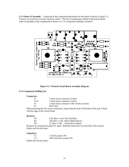
5.1.3 Order of Assembly - A drawing of the component placements for the board is shown in figure 5.2,<br />
Printed Circuit Board Assembly Diagram, below. The list of components stuffed in the board and the<br />
order of assembly of the components is shown in 5.1.4 Component Stuffing List below..<br />
5.1.4 Component Stuffing List<br />
Figure 5.2 - Printed Circuit Board Assembly Diagram<br />
Connectors<br />
J1<br />
2.5mm stereo connector (3 pins)<br />
J2 J3<br />
3.5mm stereo connector (3 pins)<br />
J4<br />
3.5mm stereo connector with switches (5 pins)<br />
J5<br />
RJ45 Jack<br />
When mounting the four stereo connectors, ensure that the front of the body of the jack is flush<br />
with the edge of the circuit board.<br />
Resistors<br />
R1<br />
8.2k ohm ¼ watt Gray Red Red<br />
R2<br />
100 ohm ¼ watt Brown Black Brown<br />
R8 51 ohm ¼ watt Green Brown Black<br />
Resistors are mounted on pads 0.4” apart. Bend the leads down on each side of the resistor.<br />
Solder and trim the leads.<br />
Capacitors<br />
C1<br />
C3<br />
Solder and trim the leads.<br />
1.0 uFd ceramic 50v<br />
.0047 uFd disc ceramic 50v<br />
12