Soundcard Isolation Project - VA3CR
Soundcard Isolation Project - VA3CR
Soundcard Isolation Project - VA3CR

You also want an ePaper? Increase the reach of your titles
YUMPU automatically turns print PDFs into web optimized ePapers that Google loves.
oth the input and output audio paths. The PTT control is also isolated using opto-isolator<br />
components.<br />
• Select the audio levels along the path to enhance S/N ratio when ever possible. This is covered in<br />
the chapter on system setup.<br />
• Ensure that the audio created by the PC is in fact the ONLY audio created by the sound card<br />
software. Other inputs to the sound card exist, and can be active unless positive steps are taken to<br />
ensure that they are turned off. This is also covered in the chapter on system setup.<br />
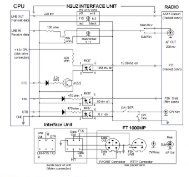
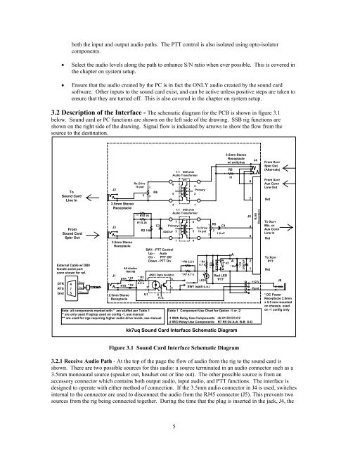
3.2 Description of the Interface - The schematic diagram for the PCB is shown in figure 3.1<br />
below. Sound card or PC functions are shown on the left side of the drawing. SSB rig functions are<br />
shown on the right side of the drawing. Signal flow is indicated by arrows to show the flow from the<br />
source to the destination.<br />
To<br />
Sound Card<br />
Line In<br />
From<br />
Sound Card<br />
Spkr Out<br />
External Cable w/ DB9<br />
female serial port<br />
conn shown for ref.<br />
DTR 4<br />
RTS 7<br />
Gnd 5<br />
Ring<br />
Tip<br />
Sleeve<br />
3.5mm Stereo<br />
Receptacle<br />
3.5mm Stereo<br />
Receptacle<br />
2.5mm Stereo<br />
Receptacle<br />
Rx Drive<br />
1k pot<br />
*** R10 1K<br />
R1 8.2k<br />
R2 100<br />
.0047uF 2<br />
All diodes<br />
1N4148<br />
4N33 Opto Isolator<br />
DTR * D1 * R3<br />
1<br />
5<br />
2.2 k<br />
RTS * D2<br />
2<br />
4<br />
6<br />
n.c.<br />
1:1 600 ohm<br />
Audio Transformer<br />
6<br />
5<br />
4<br />
SW1 - PTT Control<br />
Up - Auto<br />
Ctr - PTT Off<br />
Down - PTT On<br />
Note: all components marked with * are stuffed per Table 1<br />
** are only used if laptop used on config -1, see manual<br />
*** are used for rigs requiring higher audio drive levels, see manual<br />
J2<br />
J3<br />
J1<br />
U1<br />
1<br />
2 3<br />
R6<br />
C3<br />
1<br />
1:1 600 ohm<br />
Audio Transformer<br />
3<br />
Primary<br />
X2<br />
X1<br />
3<br />
Primary<br />
2<br />
6<br />
5<br />
1 4<br />
**R9 2.2 k<br />
* R7 4.7 k<br />
Tx Drive<br />
1k pot<br />
* R4<br />
4.7 k<br />
LED1<br />
SW1 (spdt c.o.)<br />
1 R5<br />
* D3<br />
C1<br />
2<br />
3 1.0 uF<br />
Red LED<br />
'PTT'<br />
3.5mm Stereo<br />
Receptacle<br />
w/ switches<br />
R8<br />
51<br />
A<br />
A<br />
* K1<br />
* D4<br />
Table 1 Component Use Chart for Option -1 or -2<br />
* C2<br />
.0047uF<br />
B<br />
B<br />
D<br />
D<br />
-1 With Relay Use Components J6 K1 R3 D3 C2<br />
-2 W/O Relay Use Components R7 R9 D4 A-A B-B D-D<br />
8<br />
7<br />
J5<br />
4<br />
5<br />
2<br />
1<br />
J4<br />
RJ45<br />
Receptacle<br />
+12 V<br />
Pgnd<br />
From Xcvr<br />
Spkr Out<br />
(Alternate)<br />
From Xcvr<br />
Aux Conn<br />
Line Out<br />
Ret<br />
To Xcvr<br />
Mic. or<br />
Aux Conn<br />
Line In<br />
Ret<br />
To Xcvr<br />
PTT<br />
Ret<br />
J6<br />
* DC Power<br />
Receptacle 2.5mm<br />
x 5.5 mm mounted<br />
on chassis, used<br />
on -1 config only<br />
kk7uq Sound Card Interface Schematic Diagram<br />
Figure 3.1 Sound Card Interface Schematic Diagram<br />
3.2.1 Receive Audio Path - At the top of the page the flow of audio from the rig to the sound card is<br />
shown. There are two possible sources for this audio: a source terminated in an audio connector such as a<br />
3.5mm monoaural source (speaker out, headset out or line out). The other possible source is from an<br />
accessory connector which contains both output audio, input audio, and PTT functions. The interface is<br />
designed to operate with either method of connection. If the 3.5mm audio connector in J4 is used, switches<br />
internal to the connector are used to disconnect the audio from the RJ45 connector (J5). This prevents two<br />
sources from the rig being connected together. During the time that the plug is inserted in the jack, J4, the<br />
5