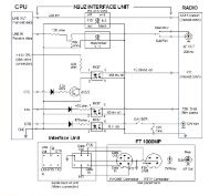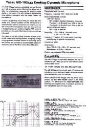
Soundcard Isolation Project - VA3CR
Soundcard Isolation Project - VA3CR
Soundcard Isolation Project - VA3CR

You also want an ePaper? Increase the reach of your titles
YUMPU automatically turns print PDFs into web optimized ePapers that Google loves.
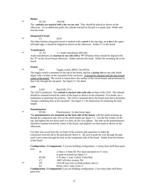
Diodes<br />
** D1 D2 1N4148<br />
The cathodes are marked with a bar on one end. They should be placed as shown on the<br />
silkscreen. As an additional guide, the cathode end pad on the pcb is a square pad. Solder and<br />
trim the leads.<br />
Integrated Circuit<br />
** U1 4N33<br />
The Opto-Isolator integrated circuit is marked with a notch at the top edge, or a dot at the upper<br />
left hand edge, it should be aligned as shown on the silkscreen. Solder U1 to the board<br />
Transformers<br />
** X1 X2 1:1 Audio transformer 600 ohm<br />
Audio transformers are marked on one side with a “P” (Primary) these should be aligned with<br />
the “P” on the circuit board silkscreen. Solder and trim the leads. Solder the mounting tab to the<br />
board.<br />
Switch<br />
** SW1 Toggle switch, SPDT, On Off On<br />
The toggle switch is mounted on the top of the board, and has a keying slot on one side which<br />
aligns with a washer on the top panel of the enclosure. It should be oriented with the slot toward<br />
center of the board. The switch is raised above the surface of the circuit board, and positioned so<br />
that it fits through the top panel. See figure 5.1 for detail.<br />
LED<br />
** LED1 Red LED, T1¾<br />
The LED is polarized. The cathode is marked with a flat side on base of the LED. The cathode<br />
should be oriented toward the center of the board as shown on the schematic. If in doubt, use a<br />
multimeter to determine the polarity. The LED is mounted above the board such that it protrudes<br />
though a matching hole in the top panel. See figure 5.1 for dimensions for trimming the lead<br />
length.<br />
Potentiometers<br />
** R5 R6 Potentiometer, 1k ohm linear taper<br />
The potentiometers are mounted on the back side of the board, with the shafts pointing up<br />
though the component side. Pre-cut the shaft lengths per figure 5.1. Use the flat washer on the<br />
top, and tighten the nut down until it is firm, do not over tighten. The tabs on the potentiometers<br />
should be oriented toward the center of the board, and aligned over their pads as shown on the<br />
silkscreen.<br />
Use bare wire saved from the cut leads of the resistors and capacitors to make the<br />
connection from the tab to the pad directly below it. Be sure to push the wire through the pad<br />
until it just comes through the hole on the component side of the board. Solder from the bottom<br />
of the board.<br />
Configuration -1 Components if you are building configuration -1 (relay) then stuff these parts<br />
now.<br />
J6<br />
2.5mm x 5.5mm DC Pwr Jack (mounted on 4” wires<br />
to pads on board) see figure 5.1<br />
R3 R4 4.7k ohm ¼ watt Yellow Violet Red<br />
C2<br />
.0047 uFd disc ceramic 50v<br />
** D3 1N4148 (see note on diode polarity above)<br />
K1<br />
Relay, reed 1 amp, Form A<br />
Configuration -2 Components if you are building configuration -2 (no relay) then stuff these<br />
parts now.<br />
13