Soundcard Isolation Project - VA3CR
Soundcard Isolation Project - VA3CR
Soundcard Isolation Project - VA3CR

You also want an ePaper? Increase the reach of your titles
YUMPU automatically turns print PDFs into web optimized ePapers that Google loves.
5 Assembly<br />
The assembly of the interface is done in four sections; PC board, cables, top panel, and enclosure.. They<br />
should be done in the order above, since the finished board is used for checking the cutout of enclosure<br />
hole patterns, and for alignment of installing the panel overlays.<br />
5.1 Printed Circuit Board (PCB) Assembly:<br />
The PCB can be assembled in one of two different configurations, -1 or -2 . See the discussion in the<br />
theory of operation section to determine which configuration is right for your rig. The differences are<br />
noted in the instructions below.<br />
5.1.1 Polarized Components - There are some components which are polarized or keyed, so attention<br />
must be paid to the orientation of the components that go on the board. These polarized/keyed components<br />
will be marked with ** in the component stuffing chart, figure 5.3.<br />
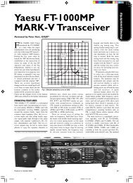
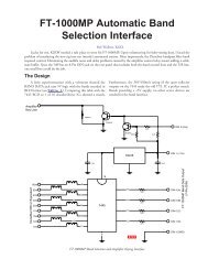
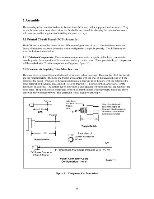
5.1.2 Components Requiring Trim Before Insertion<br />
There are three component types which must be trimmed before insertion. These are the LED, the Switch<br />
and the Potentiometers. The LED and Switch are mounted with the ends of the leads just even with the<br />
bottom of the board. When cut to the required dimension, this will align the parts with the bottom of the<br />
cover plate when the chassis is assembled. Refer to drawing 5.1, Component Cut Dimensions, for the<br />
dimension of lead cuts. The bottom nut on the switch is also adjusted to be positioned at the bottom of the<br />
cover plate. The potentiometer shafts need to be cut so that the knobs will be properly positioned above<br />
the cover plate when assembled. This dimension is also found on drawing 5.1.<br />
0.8"<br />
LED<br />
Cut Line<br />
Cut Line<br />
Note: Inner<br />
nut placed 6<br />
threads<br />
back<br />
Note: Specified switch<br />
does not need to be<br />
trimmed, this dimension is<br />
provided in case another<br />
switch is substituted<br />
1.0"<br />
Toggle Switch<br />
1.35"<br />
Potentiometer<br />
+12V<br />
Rear view of<br />
power connector<br />
PGND<br />
+12V<br />
DC Power Connector<br />
2.55 x 5.55 mm<br />
4" Pigtail leads #22 gauge insulated wire PGND<br />
Power Connector Cable<br />
Configuration -1 only<br />
Scale 1:1<br />
Figure 5.1 Component Cut Dimensions<br />
11