
You also want an ePaper? Increase the reach of your titles
YUMPU automatically turns print PDFs into web optimized ePapers that Google loves.
FT-1000MP <strong>Automatic</strong> <strong>Band</strong><br />
<strong>Selection</strong> <strong>Interface</strong><br />
Bob Wolbert, K6XX<br />
Lucky for me, K2KW needed a safe place to store his FT-1000MP. Upon volunteering for baby-sitting duty, I faced the<br />
problem of interfacing the new rig into my (mostly) automated station. Most importantly, the DuneStar bandpass filter bank<br />
required control. Eliminating the audible noise and delay problems caused by the amplifier control relay meant adding a solidstate<br />
buffer. Since the ‘MP has an 8-Pin DIN jack on the rear panel that includes both the band control lines and the T/R line,<br />
one small box could do the job.<br />
The Design<br />
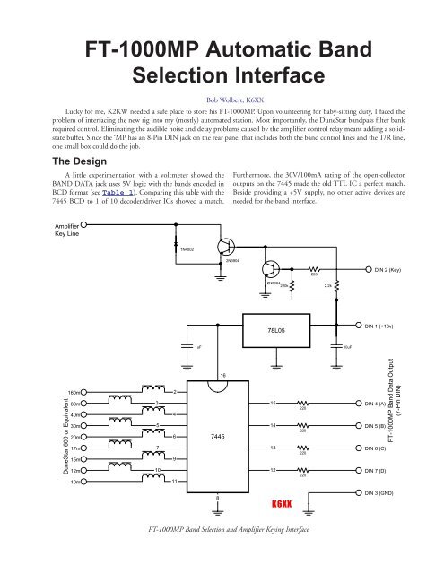
A little experimentation with a voltmeter showed the<br />
BAND DATA jack uses 5V logic with the bands encoded in<br />
BCD format (see Table 1). Comparing this table with the<br />
7445 BCD to 1 of 10 decoder/driver ICs showed a match.<br />
Furthermore, the 30V/100mA rating of the open-collector<br />
outputs on the 7445 made the old TTL IC a perfect match.<br />
Beside providing a +5V supply, no other active devices are<br />
needed for the band interface.<br />
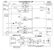
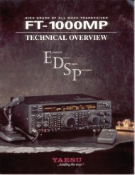
Amplifier<br />
Key Line<br />
1N4002<br />
2N3904<br />
220<br />
DIN 2 (Key)<br />
2N3904<br />
220k<br />
2.2k<br />
78L05<br />
DIN 1 (+13v)<br />
1uF<br />
10uF<br />
DuneStar 600 or Equivalent<br />
160m<br />
80m<br />
40m<br />
30m<br />
20m<br />
17m<br />
15m<br />
12m<br />
10m<br />
3<br />
5<br />
7<br />
10<br />
2<br />
4<br />
6<br />
9<br />
11<br />
16<br />
7445<br />
15<br />
14<br />
13<br />
12<br />
220<br />
220<br />
220<br />
220<br />
DIN 4 (A)<br />
DIN 5 (B)<br />
DIN 6 (C)<br />
DIN 7 (D)<br />
FT-1000MP <strong>Band</strong> Data Output<br />
(7-Pin DIN)<br />
8<br />
K6XX<br />
DIN 3 (GND)<br />
FT-1000MP <strong>Band</strong> <strong>Selection</strong> and Amplifier Keying <strong>Interface</strong>
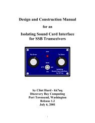
Table 1. BAND DATA Code<br />
BAND DATA<br />
<strong>Band</strong><br />
D C B A<br />
0 0 0 0 —<br />
0 0 0 1 160m<br />
0 0 1 0 80m<br />
0 0 1 1 40m<br />
0 1 0 0 30m<br />
0 1 0 1 20m<br />
0 1 1 0 17m<br />
0 1 1 1 15m<br />
1 0 0 0 12m<br />
1 0 0 1 10m<br />
BAND DATA Pin 2, TX GND, is an open-collector output<br />
that SHOULD be perfect for driving amplifiers, QSK or<br />
otherwise. Unfortunately, Yaesu chose to use a wimpy little transistor<br />
that can only handle 15V at 100mA. The 15V is too low<br />
for my Alpha, and the 100mA is too marginal for my Ameritrons,<br />
especially with the Relay Accelerator circuit<br />
employed. Since every rig must operate with every amplifier in<br />
case anything breaks during a contest, all interfaces must handle<br />
the worst-case combination, meaning the TX GND output<br />
needs buffering. NOTE: the TX GND mentioned here is Pin 2<br />
on the BAND DATA connector, not the dedicated phono jack output<br />
on the rear panel of the ‘MP. The phono jack output is from the<br />
internal relay and is disabled when the LIN SW is turned OFF;<br />
the DIN output remains active regardless of switch setting. The<br />
buffer consists of two transistors, each connected as a basic inverter.<br />
Circuit Implementation<br />
The design is nearly complete. The 5V regulator needs<br />
two capacitors of noncritical value. Power dissipation for the<br />
TO-92 package is 360mW; a bit high. Adding a 100Ω, ½W<br />
resistor in the input lead (between the DIN pin and the capacitor,<br />
not between the capacitor and the regulator) reduces IC<br />
heating. Or, like me, you could use a TO-220 regulator package<br />
instead. The circuit was constructed on perf-board.<br />
Some RF problems in the prototype lead to the 220Ω resistors<br />
in series with each input and the inductors in the output<br />
lines. Neither inductor nor resistor values are critical; resistors<br />
should not be much larger due to the input current of the 7445<br />
(remember, this is old-style TTL).<br />
My second version uses an IRF510 N-channel MOSFET<br />
as the keying transistor. Now, the Key Line output is rated to<br />
100V and 5A, just in case some strange amplifier needs that<br />
capability. With a MOSFET output, the 2.2kΩ resistor becomes<br />
22kΩ and the 1N4001 diode is unnecessary. One final<br />
option is a switch that disables the DuneStar power when<br />
SWLing; even megapower broadcasters are hard to copy when<br />
the filters chop them out!<br />
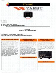
Table 2. FT-1000MP BAND DATA Jack Pinout<br />
DIN # Name Function<br />
1 +13V Aux. power supply<br />
output<br />
2 TX GND Open collector T/R<br />
switch, active low<br />
3 GND Ground<br />
4 BAND DATA A See Table 1<br />
5 BAND DATA B See Table 1<br />
6 BAND DATA C See Table 1<br />
7 BAND DATA D See Table 1<br />
8 TX INHIBIT Handshake*<br />
* Ensures amplifier is ready for RF power. Not used in<br />
this interface.<br />
Operation<br />
This is the best part. Once the interface is built and connected,<br />
no user intervention is required. Change the frequency<br />
of the FT-1000MP and the DuneStar bandpass filter bank<br />
switches automatically. Now turn off the LIN EN switch and<br />
run silent QSK with “real” amplifiers. “Baby-sitting” has rarely<br />
been this much fun!<br />
Comments Please e-mail k6xx@arrl.net<br />
Version 1.1, June 2000<br />
Copyright © 1999, 2000 26K Engineering & Bob Wolbert