Soundcard Isolation Project - VA3CR
Soundcard Isolation Project - VA3CR
Soundcard Isolation Project - VA3CR

You also want an ePaper? Increase the reach of your titles
YUMPU automatically turns print PDFs into web optimized ePapers that Google loves.
cable can be momentarily shorted, hence resistor R8 is used to provide a load during this short time<br />
interval.<br />
The audio from one of these two sources is sent to the primary of transformer X2. The output of the<br />
transformer feeds potentiometer R6 which is used to control the signal output level sent on to the PC sound<br />
card. The output connector is a 3.5mm stereo jack since the sound card expects stereo input. Only the TIP<br />
(left channel) connection is used. The connection to the sound card should be a shielded stereo cable.<br />
3.2.2 Transmit Audio Path - In the center of the page, the audio path from the sound card to the rig is<br />
shown. The sound card output is provided in the form of a shielded stereo audio cable. The TIP (right<br />
hand channel) connection of 3.5mm audio jack J3 carries this signal. The other channel is not connected.<br />
As will be seen in chapter on system setup, there is an advantage to only using one of the two channels.<br />
The audio goes to voltage divider R1/R2. This provides a signal level reduction of about 82:1. Signal<br />
levels of around 1 volts become around 10 millivolt after this divider. There are some rigs whose<br />
accessory ports require substantially higher drive, in the range of 100 millivolt. For these rigs, an extra set<br />
of pads in position R10 is provided to place a 1k ohm resistor in parallel with R1. This changes the signal<br />
level reduction to about 10:1.<br />
Capacitor C3 is provided across the primary side of transformer X1. This acts as a filter for any RF present<br />
on the audio input line. The output of the X1 feeds a potentiometer (R5) to allow for final adjustment of<br />
signal level going to the SSB rig. The wiper of the potentiometer is fed through capacitor C1 to provide<br />
DC blocking of the signal sent to the SSB rig.<br />
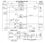
An RJ-45 jack is provided as the method of connecting to the SSB rig. This connector is set up to allow<br />
feeding the microphone jack of the rig, or an accessory connector, if available. Signals on this connector<br />
include the audio received from the SSB rig, the audio sent to the SSB rig and the PTT control of the rig.<br />
Notice that the return lines (normally chassis ground of the rig) are not tied together in the interface. They<br />
are only tied together at the connector to the rig itself. Pinouts used on the connector are chosen to be<br />
compatible with the twisted pair sets on a standard CAT 5 patch cable.<br />
3.2.3 PTT - The Push To Talk (PTT) rig function is used to turn on the transmitter when sending audio to<br />
the rig through the interface. The PTT Control circuit is described below.<br />
3.2.3.1 PTT Control - The PTT (Push to Talk) control circuit is shown at the bottom of the diagram. The<br />
interface is set up to activate PTT under the control of a serial port of the PC. Historically, two different<br />
signals have been used to perform this function for ham radio sound card applications: RTS (request to<br />
send) and DTR (data terminal ready). One or both of these signals have been used by different software<br />
written for these applications. Today, most software has been rewritten to activate BOTH of these lines to<br />
maintain compatibility. Hence there are two diodes D1 and D2 which perform a logical OR of these two<br />
signals so that either one will activate the rig. The output of the diodes is used to feed an opto-isolator<br />
(U1) which in turn is used to activate the PTT line. The connection to the interface is via a 2.5mm three<br />
conductor jack, J1. An external cable which connects the DB9 type connector of the PC to the 2.5mm plug<br />
must be provided. The construction of this cable is described in section 5.2.1.<br />
3.2.3.2 PTT Configuration -1 With Relay - Two configurations of PTT drive are provided with the<br />
interface. The first configuration, designated -1 drives a reed relay in the interface whose output contacts<br />
drive the PTT line. A capacitor, C2, is provided across these contacts in case they feed an inductive source<br />
such as a relay coil. The -1 configuration is used for older, tube type rigs which have relay coils connected<br />
to the PTT line. This configuration requires a power source from 12V to 13.8 volt DC to power the reed<br />
relay coil. This is connected to the board via DC power connector J6, mounted external to the board on the<br />
back of the enclosure. There is a short “captive cable” between J6 and the PCB. In this configuration,<br />
components R7 and D4 are NOT stuffed on the board, nor are jumpers A-A, B-B or D-D used.<br />
6