Soundcard Isolation Project - VA3CR
Soundcard Isolation Project - VA3CR
Soundcard Isolation Project - VA3CR
You also want an ePaper? Increase the reach of your titles
YUMPU automatically turns print PDFs into web optimized ePapers that Google loves.
1 Introduction<br />
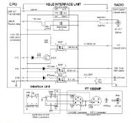
1.1 Scope - This manual describes the design and assembly of an interface between a PC and a SSB rig.<br />
Included in this manual are sections describing the theory of operation of the interface, material list and<br />
parts ordering guidelines, assembly procedures, system setup and testing, and web links to find software<br />
for operating in PSK31, MFSK16, RTTY, SSTV and CW using the sound card in your PC as the signal<br />
processor.<br />
1.2 Intended Use - This design has been created for the amateur radio community to encourage more<br />
hams to enjoy the pleasures of the new sound card digital modes. This design is ideal for ham club<br />
construction projects and for individual hams who likes to build their own equipment. The end result is a<br />
solid interface for use with sound card modes such as PSK31, MFSK16, RTTY, Hellschreiber and SSTV.<br />
1.3 Copyright and Ownership - all material in this manual is copyright (c) 2001, Discovery Bay<br />
Computing. Copies may be made of these materials, for the personal use of licensed radio amateurs. NO<br />
commercial use of the designs may be made without express written consent of Discovery Bay Computing.<br />
1.4 Caveats and Disclaimers- the designs represented in this manual have been tested in on the air<br />
amateur radio operation and are believed to be accurate. Clint Hurd, and Discovery Bay Computing are<br />
not responsible for errors, mistakes or omissions made by others when building from these designs. No<br />
claims are made to the use or application of the principles in these designs or fitness for any particular<br />
purpose. Clint Hurd and Discovery Bay computing are NOT liable for consequential damages resulting<br />
from the use of these designs.<br />
1.5 Features - The main features of this design include:<br />
• Ground paths between the PC and the SSB rig that travel through the interconnecting cables<br />
are completely eliminated through the use of transformers and an opto-isolator.<br />
• Potentiometers are provided on both Rx and Tx to allow easy level adjustment during<br />
operation. Knobs are located on the top of the enclosure for easy adjustment.<br />
• LED provided to show when the PC PTT control line is activated.<br />
• Switch provided to enable/disable automatic PTT, or to force the rig PTT ON for manual<br />
operation and test.<br />
• Design implemented on a PCB to reduce wiring lengths and simplify assembly.<br />
• Packaged in a small enclosure consistent with the reduced size of the modern transceiver.<br />
The enclosure measures 4.1”w x 2.7”d x 1.6” h.<br />
• Templates provided for hole location on the enclosure and top panel.<br />
• Panel label overlays provided for top and rear panel.<br />
• Can be interfaced to either the rig’s microphone/line out or to a single accessory port on the<br />
rig.<br />
• Interface can be configured for solid state drive of PTT or for relay contact closure for use<br />
with older tube type transceivers.<br />
1


