Soundcard Isolation Project - VA3CR
Soundcard Isolation Project - VA3CR
Soundcard Isolation Project - VA3CR
Create successful ePaper yourself
Turn your PDF publications into a flip-book with our unique Google optimized e-Paper software.
3.1.1 Bandwidth - To realize this low bandwidth and close signal separation, some care must be taken in<br />
adjustment of the audio drive of the transmitter from the PC, and particular attention must be paid to<br />
minimizing stray signal pickup from sources such as the RF field of the transmitter, AC power lines and<br />
other sources. It is the job of the interface system to provide clean signals to the transmitter in this<br />
potentially hostile environment.<br />
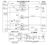
The basic concept is very straight forward. During transmit, audio output from the PC sound card is<br />
provided at the microphone (or accessory port) of the SSB rig. The SSB rig is keyed using the PTT input<br />
to the rig. Data input from the operator is provided by the keyboard to the sound card software. The sound<br />
card software converts it to the modulation format and uses the sound card to create the audio output for<br />
the SSB rig.<br />
During receive, the audio from the SSB rig is connected to the audio input of the PC sound card, and the<br />
sound card software decodes the audio signal and provides text output on the screen.<br />
3.1.2 Software Functions - The software running on the PC provides the functions of:<br />
• Operator Interface - Keyboard and Screen<br />
• Scanning a portion of the audio band (200 to 4000 Hz) and presenting a view of this spectrum<br />
on a waterfall or spectrum display<br />
• Selection of a particular signal, filtering it to separate from other signals and decoding it.<br />
• Presenting the output to the screen.<br />
• When ready to transmit, accepting the data via keyboard and converting the keyboard data to<br />
a modulated audio output to be sent to the SSB rig.<br />
3.1.3 SSB Rig Audio Levels - are consistent with driving speakers or headsets. These signals have an<br />
extremely wide dynamic range: from millivolts to around 5 V p-p. The PC Sound Card accepts levels up<br />
to about 5v p-p. In general, the audio levels from the rig to the sound card are compatible. If signals<br />
approach the maximum range of the sound card input, a warning message from the software will be given<br />
for the operator to reduce the audio level. The receive audio level can be controlled by RF gain of the<br />
receiver, input gain of the sound card, or the RX level control potentiometer in the interface. In practice,<br />
all of these controls are used during setup and operation of the system.<br />
3.1.4 PC Sound Card Audio Levels - The audio levels created from the sound card are in the range of 0.1<br />
to 5 v p-p. Typical signal level is around 1V p-p. The SSB rig, however, expects signals that are<br />
compatible with microphones, i.e. in the tens of millivolts range. The interface must provide some level<br />
reduction to bring the signals to the right scale. The actual level required is a function of the microphone<br />
gain setting of the rig, the audio level of the PC soundcard and the TX level control potentiometer in the<br />
interface. All of these controls are set during the system setup, covered in chapter 6.<br />
3.1.5 Noise & Feedback - One problem with lower level input is that any signal picked up on the transmit<br />
audio wiring can approach the expected signal level, degrading S/N and putting unwanted signals on the<br />
transmitted audio. If the noise source is the RF created by the transmitter, feedback will occur with broad<br />
band noise resulting on the transmitted audio. There are several lines of defense that can be taken to ensure<br />
clean, quiet operation.<br />
• Shield the cables, and provide good ground connections for all components of the system,<br />
including the PC.<br />
• Provide a filter in the interface to remove unwanted RF signals that have been picked up. This<br />
combined with short lead lengths in the cables from the interface to the rig can be very effective.<br />
• Eliminate any ground loop between the components placed along the signal path which may inject<br />
common mode noise into the audio. This is done in the interface by using audio transformers on<br />
4


