Soundcard Isolation Project - VA3CR
Soundcard Isolation Project - VA3CR
Soundcard Isolation Project - VA3CR

Create successful ePaper yourself
Turn your PDF publications into a flip-book with our unique Google optimized e-Paper software.
made in the overlay paper on the four mounting holes should just slide into the gap between the nail and<br />
the hole in the plate. When you are sure that the overlay and panel align properly, remove the overlay and<br />
apply adhesive to the back of the overlay with spray on contact adhesive, per the instructions on the can.<br />
Then slide the overlay along the nails and drop the overlay in place on the panel. Smooth out the overlay<br />
from the center toward the outside in case there are any bubbles in the surface.<br />
A good adhesive is Elmer’s “Craft Bond Multi Purpose Spray Adhesive”. Other contact adhesives suitable<br />
for mounting photographs in albums will also work. Follow the instructions on the can. DO NOT<br />
OVERSPRAY.<br />
Let the completed assembly dry for a few minutes, then remove the panel/overlay from the jig and turn the<br />
panel face side down on a surface that you can cut on. Remove the excess overlay paper around the edges<br />
of the panel with an exacto knife. The panel/overlay should be ready for use at this time.<br />
Note: if you are unsure about being able to apply the overlay with the adhesive on it, the overlay can be<br />
used without the adhesive, it will be held in place fairly well by the four mounting screws and the switch<br />
washer and nut.<br />
5.4 Enclosure<br />
The enclosure is a black plastic box, 4.1” W x 2.7” D x 1.6” H. Holes will be drilled and cut in the back of<br />
the box.<br />
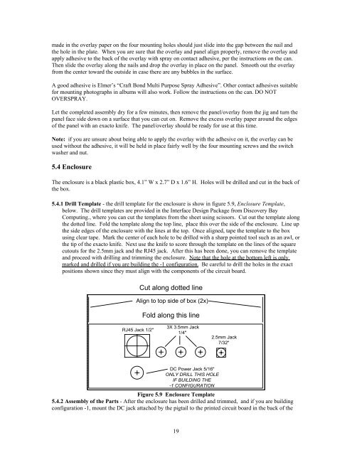
5.4.1 Drill Template - the drill template for the enclosure is show in figure 5.9, Enclosure Template,<br />
below. The drill templates are provided in the Interface Design Package from Discovery Bay<br />
Computing., where you can cut the templates from the sheet using scissors. Cut out the template along<br />
the dotted line. Fold the template along the top line, place this over the side of the enclosure. Line up<br />
the side edges of the enclosure with the lines at the top. Once aligned, tape the template to the box<br />
using clear tape. Mark the center of each hole to be drilled with a sharp pointed tool such as an awl, or<br />
the tip of the exacto knife. Next use the knife to score through the template on the lines of the square<br />
cutouts for the 2.5mm jack and the RJ45 jack. After this has been done, you can remove the template<br />
and proceed with drilling and trimming the enclosure. Note that the hole at the bottom left is only<br />
marked and drilled if you are building the -1 configuration. Be careful to drill the holes in the exact<br />
positions shown since they must align with the components of the circuit board.<br />
Cut along dotted line<br />
Align to top side of box (2x)<br />
Fold along this line<br />
RJ45 Jack 1/2"<br />
3X 3.5mm Jack<br />
1/4"<br />
2.5mm Jack<br />
7/32"<br />
DC Power Jack 5/16"<br />
ONLY DRILL THIS HOLE<br />
IF BUILDING THE<br />
-1 CONFIGURATION<br />
Figure 5.9 Enclosure Template<br />
5.4.2 Assembly of the Parts - After the enclosure has been drilled and trimmed, and if you are building<br />
configuration -1, mount the DC jack attached by the pigtail to the printed circuit board in the back of the<br />
19