A graphene-based broadband optical modulator
A graphene-based broadband optical modulator
A graphene-based broadband optical modulator

Create successful ePaper yourself
Turn your PDF publications into a flip-book with our unique Google optimized e-Paper software.
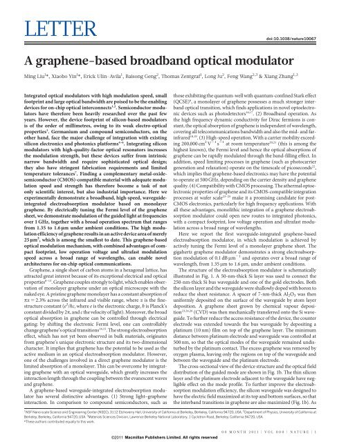
LETTER<br />
doi:10.1038/nature10067<br />
A <strong>graphene</strong>-<strong>based</strong> <strong>broadband</strong> <strong>optical</strong> <strong>modulator</strong><br />
Ming Liu 1 *, Xiaobo Yin 1 *, Erick Ulin-Avila 1 , Baisong Geng 2 , Thomas Zentgraf 1 , Long Ju 2 , Feng Wang 2,3 & Xiang Zhang 1,3<br />
Integrated <strong>optical</strong> <strong>modulator</strong>s with high modulation speed, small<br />
footprint and large <strong>optical</strong> bandwidth are poised to be the enabling<br />
devices for on-chip <strong>optical</strong> interconnects 1,2 . Semiconductor <strong>modulator</strong>s<br />
have therefore been heavily researched over the past few<br />
years. However, the device footprint of silicon-<strong>based</strong> <strong>modulator</strong>s<br />
is of the order of millimetres, owing to its weak electro-<strong>optical</strong><br />
properties 3 . Germanium and compound semiconductors, on the<br />
other hand, face the major challenge of integration with existing<br />
silicon electronics and photonics platforms 4–6 . Integrating silicon<br />
<strong>modulator</strong>s with high-quality-factor <strong>optical</strong> resonators increases<br />
the modulation strength, but these devices suffer from intrinsic<br />
narrow bandwidth and require sophisticated <strong>optical</strong> design;<br />
they also have stringent fabrication requirements and limited<br />
temperature tolerances 7 . Finding a complementary metal-oxidesemiconductor<br />
(CMOS)-compatible material with adequate modulation<br />
speed and strength has therefore become a task of not<br />
only scientific interest, but also industrial importance. Here we<br />
experimentally demonstrate a <strong>broadband</strong>, high-speed, waveguideintegrated<br />
electroabsorption <strong>modulator</strong> <strong>based</strong> on monolayer<br />
<strong>graphene</strong>. By electrically tuning the Fermi level of the <strong>graphene</strong><br />
sheet, we demonstrate modulation of the guided light at frequencies<br />
over 1 GHz, together with a broad operation spectrum that ranges<br />
from 1.35 to 1.6 mm under ambient conditions. The high modulation<br />
efficiency of <strong>graphene</strong> results in an active device area of merely<br />
25 mm 2 , which is among the smallest to date. This <strong>graphene</strong>-<strong>based</strong><br />
<strong>optical</strong> modulation mechanism, with combined advantages of compact<br />
footprint, low operation voltage and ultrafast modulation<br />
speed across a broad range of wavelengths, can enable novel<br />
architectures for on-chip <strong>optical</strong> communications.<br />
Graphene, a single sheet of carbon atoms in a hexagonal lattice, has<br />
attracted great interest because of its exceptional electrical and <strong>optical</strong><br />
properties 8–13 . Graphene couples strongly to light, which enables observation<br />
of monolayer <strong>graphene</strong> under an <strong>optical</strong> microscope with the<br />
naked eye. A pristine <strong>graphene</strong> monolayer has a constant absorption of<br />
pa 5 2.3% across the infrared and visible range, where a is the finestructure<br />
constant (e 2 /Bc, where e is the electronic charge, B is Planck’s<br />
constant divided by 2p,andc the velocity of light). Moreover, the broad<br />
<strong>optical</strong> absorption in <strong>graphene</strong> can be controlled through electrical<br />
gating: by shifting the electronic Fermi level, one can controllably<br />
change <strong>graphene</strong>’s <strong>optical</strong> transitions 14,15 . The strong electroabsorption<br />
effect, which has not yet been observed in bulk materials, originates<br />
from <strong>graphene</strong>’s unique electronic structure and its two-dimensional<br />
character. It implies that <strong>graphene</strong> has the potential to be used as the<br />
active medium in an <strong>optical</strong> electroabsorption <strong>modulator</strong>. However,<br />
one of the challenges involved in a direct <strong>graphene</strong> <strong>modulator</strong> is the<br />
limited absorption of a monolayer. This can be overcome by integrating<br />
<strong>graphene</strong> with an <strong>optical</strong> waveguide, which greatly increases the<br />
interaction length through the coupling between the evanescent waves<br />
and <strong>graphene</strong>.<br />
A <strong>graphene</strong>-<strong>based</strong> waveguide-integrated electroabsorption <strong>modulator</strong><br />
has several distinctive advantages. (1) Strong light–<strong>graphene</strong><br />
interaction. In comparison to compound semiconductors, such as<br />
those exhibiting the quantum-well with quantum-confined Stark effect<br />
(QCSE) 6 , a monolayer of <strong>graphene</strong> possesses a much stronger interband<br />
<strong>optical</strong> transition, which finds applications in novel optoelectronic<br />
devices such as photodetectors 16,17 . (2) Broadband operation. As<br />
the high frequency dynamic conductivity for Dirac fermions is constant,<br />
the <strong>optical</strong> absorption of <strong>graphene</strong> is independent of wavelength,<br />
covering all telecommunications bandwidth and also the mid- and farinfrared<br />
18,19 . (3) High-speed operation. With a carrier mobility exceeding<br />
200,000 cm 2 V 21 s 21 at room temperature 20,21 (this is among the<br />
highest known), the Fermi level and hence the <strong>optical</strong> absorptions of<br />
<strong>graphene</strong> can be rapidly modulated through the band-filling effect. In<br />
addition, speed limiting processes in <strong>graphene</strong> (such as photocarrier<br />
generation and relaxation) operate on the timescale of picoseconds 22 ,<br />
which implies that <strong>graphene</strong>-<strong>based</strong> electronics may have the potential<br />
to operate at 500 GHz, depending on the carrier density and <strong>graphene</strong><br />
quality. (4) Compatibility with CMOS processing. The athermal optoelectronic<br />
properties of <strong>graphene</strong> and its CMOS-compatible integration<br />
processes at wafer scale 23–25 make it a promising candidate for post-<br />
CMOS electronics, particularly for high frequency applications. With<br />
all these advantages, monolithic integration of a <strong>graphene</strong> electroabsorption<br />
<strong>modulator</strong> could open new routes to integrated photonics,<br />
with a compact footprint, low voltage operation and ultrafast modulation<br />
across a broad range of wavelengths.<br />
Here we report the first waveguide-integrated <strong>graphene</strong>-<strong>based</strong><br />
electroabsorption <strong>modulator</strong>, in which modulation is achieved by<br />
actively tuning the Fermi level of a monolayer <strong>graphene</strong> sheet. The<br />
gigahertz <strong>graphene</strong> <strong>modulator</strong> demonstrates a strong electroabsorption<br />
modulation of 0.1 dB mm 21 and operates over a broad range of<br />
wavelength, from 1.35 mm to1.6mm, under ambient conditions.<br />
The structure of the electroabsorption <strong>modulator</strong> is schematically<br />
illustrated in Fig. 1. A 50-nm-thick Si layer was used to connect the<br />
250-nm-thick Si bus waveguide and one of the gold electrodes. Both<br />
the silicon layer and the waveguide were shallowly doped with boron to<br />
reduce the sheet resistance. A spacer of 7-nm-thick Al 2 O 3 was then<br />
uniformly deposited on the surface of the waveguide by atom layer<br />
deposition. A <strong>graphene</strong> sheet grown by chemical vapour deposition<br />
23,24,26 (CVD) was then mechanically transferred onto the Si waveguide.<br />
To further reduce the access resistance of the device, the counter<br />
electrode was extended towards the bus waveguide by depositing a<br />
platinum (10 nm) film on top of the <strong>graphene</strong> layer. The minimum<br />
distance between platinum electrode and waveguide was controlled at<br />
500 nm, so that the <strong>optical</strong> modes of the waveguide remained undisturbed<br />
by the platinum contact. The excess <strong>graphene</strong> was removed by<br />
oxygen plasma, leaving only the regions on top of the waveguide and<br />
between the waveguide and the platinum electrode.<br />
The cross-sectional view of the device structure and the <strong>optical</strong> field<br />
distribution of the guided mode are shown in Fig. 1b. The thin silicon<br />
layer and the platinum electrode adjacent to the waveguide have negligible<br />
effect on the mode profile. To further improve the electroabsorption<br />
modulation efficiency, the silicon waveguide was designed to<br />
have the electric field maximized at its top and bottom surfaces, so that<br />
the interband transitions in <strong>graphene</strong> are also maximized (Fig. 1b). As<br />
1 NSF Nano-scale Science and Engineering Center (NSEC), 3112 Etcheverry Hall, University of California at Berkeley, Berkeley, California 94720, USA. 2 Department of Physics, University of California at<br />
Berkeley, Berkeley, California 94720, USA. 3 Materials Sciences Division, Lawrence Berkeley National Laboratory, 1 Cyclotron Road, Berkeley, California 94720, USA.<br />
*These authors contributed equally to this work.<br />
©2011 Macmillan Publishers Limited. All rights reserved<br />
00 MONTH 2011 | VOL 000 | NATURE | 1
RESEARCH<br />
LETTER<br />
a<br />
c<br />
Couple out<br />
Couple in<br />
d<br />
b<br />
Pt<br />
Graphene<br />
Al 2 O 3<br />
Si<br />
Graphene<br />
Al 2 O 3<br />
Si<br />
Si waveguide<br />
Pt<br />
Graphene<br />
SiO 2<br />
Au<br />
2 μm<br />
Figure 1 | A <strong>graphene</strong>-<strong>based</strong> waveguide-integrated <strong>optical</strong> <strong>modulator</strong>.<br />
a, Three-dimensional schematic illustration of the device; a monolayer<br />
<strong>graphene</strong> sheet is on top of a silicon bus waveguide, separated from it by a<br />
7-nm-thick Al 2 O 3 layer (not shown). The silicon waveguide is doped, and<br />
connected to the electrode (right, shown gold) through a thin layer of silicon<br />
defined by selective etching. b, Left, cross-section of the device, with an overlay<br />
of the <strong>optical</strong> mode plot, calculated by finite element simulation. The waveguide<br />
was carrying a single <strong>optical</strong> mode, and was designed so as to maximize the field<br />
at the interface between the waveguide and the <strong>graphene</strong>, to maximize the<br />
absorption efficiency. The thin silicon layer and the Pt electrode, which is<br />
500 nm away from the waveguide, have negligible influence on the <strong>optical</strong><br />
mode. Right, a cross-section through the centre of the waveguide; the purple<br />
<strong>graphene</strong> only interacts with the tangential (in-plane) electric field<br />
of electromagnetic waves, the <strong>graphene</strong> <strong>modulator</strong> is polarizationsensitive,<br />
as are conventional semiconductor-<strong>based</strong> electro-<strong>optical</strong><br />
<strong>modulator</strong>s 3 .<br />
Figure 1c shows a top-view <strong>optical</strong> microscope image of the device,<br />
and a close-up scanning electron microscopy image of the active<br />
region is given in Fig. 1d. The <strong>graphene</strong> sheet, highlighted in Fig. 1d<br />
by a false blue colour, covers only the waveguide region; this is to<br />
minimize the capacitance. The platinum electrode (green) is placed<br />
500 nm away from the 600-nm-wide Si waveguide. Light was coupled<br />
in and out of the waveguide through tapered gratings, which contribute<br />
most to the overall loss of the system. The Si waveguide was bent 90u to<br />
change the polarization state between the input and the output light, to<br />
improve the signal-noise ratio.<br />
Figure 2 displays the transmission of 1.53 mm photons through the<br />
waveguide at different drive voltages, V D . At low drive voltage<br />
(21V, V D , 3.8 V), the Fermi level E F (V D ) of <strong>graphene</strong> is close to<br />
the Dirac point (E F (V D ) , hn 0 /2), and interband transitions occur<br />
when electrons are excited by the incoming photons (hn 0 ). The <strong>optical</strong><br />
absorption of <strong>graphene</strong> is determined by the position of the Fermi<br />
level. By applying a drive voltage between the <strong>graphene</strong> and the waveguide,<br />
we can tune the Fermi level of the <strong>graphene</strong>, and therefore<br />
modulate the total transmission. With the current waveguide design,<br />
the modulation depth is as high as 0.1 dB mm 21 , resulting in a <strong>graphene</strong><br />
electroabsorption <strong>modulator</strong> with a footprint of merely 25 mm 2 .<br />
At large negative V D (,21 V), the Fermi level is lowered below the<br />
transition threshold (E F (V D ) 5 hn 0 /2) owing to positive charge accumulation.<br />
As a result, there are no electrons available for interband<br />
transitions, and hence the <strong>graphene</strong> appears transparent. On the other<br />
hand, at large positive V D (.3.8 V), all electron states are filled up, and<br />
no interband transitions are allowed. Ideally, there should be a sharp<br />
change in transmission at E F (V D ) 5 hn 0 /2. In reality, this transition<br />
was broadened owing to defects in the <strong>graphene</strong>, and shifted to higher<br />
voltage owing to natural doping from the substrate 27 . When the <strong>modulator</strong><br />
is in operation (that is, when no interband absorption is allowed),<br />
curve shows the magnitude of the electric field. The actual thicknesses of the<br />
<strong>graphene</strong> sheet and the Al 2 O 3 in the simulation are 0.7 nm and 7 nm,<br />
respectively. c, Top-view <strong>optical</strong> microscope image of the waveguide. The Si<br />
waveguide was bent by 90u to change the polarization state between the input<br />
and the output light, to improve the signal-noise ratio. d, SEM image showing<br />
the boxed region in c at higher magnification, showing the detailed structure of<br />
the <strong>graphene</strong> <strong>modulator</strong>. False colours are used to highlight the Au electrode<br />
(yellow), the Pt electrode (Green), the <strong>graphene</strong> sheet (blue) and the waveguide<br />
(red). The width of the Si waveguide is 600 nm, while the distance between the<br />
Pt electrode and the Si waveguide is 500 nm. The bright multi-ring region<br />
beside the Au electrodes is due to a charging effect on the SiO 2 layer in the SEM.<br />
its insertion loss is negligible as the intraband absorption of <strong>graphene</strong> is<br />
extremely low at near-infrared wavelengths 28 .<br />
To measure the dynamic response of the <strong>graphene</strong> <strong>modulator</strong>, radio<br />
frequency signals generated by a network analyser were added on a<br />
static V D and applied to the <strong>modulator</strong>. The same 1.53-mm laser was<br />
used to test the <strong>modulator</strong>, and the out-coupled light was sent to a<br />
high-speed photodetector. Shown in Fig. 3 are the V D -dependent r.f.<br />
responses of the <strong>graphene</strong> <strong>modulator</strong>; gigahertz operation of the device<br />
Transmission (dB μm –1 )<br />
0.00<br />
–0.03<br />
–0.06<br />
hν/2<br />
–hν/2<br />
–0.09<br />
–6<br />
E F<br />
–4 –2 0<br />
Drive voltage (V)<br />
E F<br />
E F<br />
2 4 6<br />
Figure 2 | Static electro-<strong>optical</strong> response of the device at different drive<br />
voltages. The main panel shows the modulation depth, normalized to the<br />
device length (40 mm), at different drive voltages (V D ). Three regions can be<br />
seen, and their band structures are shown as insets. In the middle region (with<br />
V D in the range 21 V to 3.8 V), the Fermi level (E F , black dashed line) is close to<br />
the Dirac point and the interband transition is allowed from electron-occupied<br />
regions (red lines) to unoccupied regions (green lines). Thus the <strong>graphene</strong> sheet<br />
is absorptive to incident photons (hn), resulting in a modulation depth of<br />
0.1 dB mm 21 and a miniaturized footprint of the <strong>modulator</strong>. In the left-hand<br />
region (with V D , 21 V), the Fermi level (E F ) is lower than half the photon<br />
energy (2hn/2, blue dashed line) and there are no electrons available for the<br />
interband transition. In the right-hand region (with V D . 3.8 V), all electron<br />
states in resonance with incident photons (hn) are occupied, and the transition<br />
is forbidden. In both of the last two cases, the transmission increases. The<br />
natural doping from the substrate offsets the centre of the absorption curve<br />
from zero bias. The transmission is measured at a laser wavelength of 1.53 mm.<br />
2 | NATURE | VOL 000 | 00 MONTH 2011<br />
©2011 Macmillan Publishers Limited. All rights reserved
LETTER<br />
RESEARCH<br />
a<br />
–84<br />
Response (dBm)<br />
–90<br />
–96<br />
–102<br />
–108<br />
Response (dBm)<br />
–80<br />
–90<br />
–2.0 V<br />
–2.5 V<br />
–100<br />
–3.0 V<br />
–3.5 V<br />
–5 –4 –3 –2 –1<br />
Drive voltage (V)<br />
10 8 10 9<br />
Frequency (Hz)<br />
Transmission (a.u.)<br />
2.5<br />
2.0<br />
1.5<br />
1.0<br />
b<br />
0.85<br />
–4<br />
–2<br />
Drive voltage (V)<br />
0<br />
2<br />
1,500<br />
1,450<br />
1,400<br />
1,350<br />
Wavelength (nm)<br />
Figure 3 | Dynamic electro-<strong>optical</strong> response of the device. The main panel<br />
shows the response of the device as a function of frequency. Each curve<br />
corresponds to a different drive voltage: 22.0 V, 22.5 V, 23.0 V and 23.5 V<br />
(black, red, blue and green curve, respectively). The measured 3 dB bandwidths<br />
of the device are respectively 0.8 GHz, 1.1 GHz, 1.1 GHz and 1.2 GHz; the<br />
bandwidths are mainly restricted by the parasitic response of the device. Inset,<br />
low-frequency device response with different drive voltages, indicating that the<br />
device has best performance at a drive voltage of 24 V. The laser wavelength is<br />
1.53 mm in the test.<br />
Energy 2 (eV 2 )<br />
0.80<br />
0.75<br />
0.70<br />
at various drive voltages is obtained. Owing to the exceptionally high<br />
carrier mobility and saturation velocity of <strong>graphene</strong>, the bandwidth is<br />
not limited by the carrier transit time, but by the parasitic response of<br />
the device. With the platinum electrode placed 500 nm away from the<br />
waveguide, the total resistance of the system is reduced to around<br />
600 V. This resistance, together with the capacitance (of the order of<br />
0.22 pF), limits the operation bandwidth of the present device to about<br />
1 GHz (see Fig. 3 legend).<br />
The device response at low frequency (300 kHz) is shown in Fig. 3<br />
inset. At low V D , the modulation response is weak, as the <strong>optical</strong><br />
transmission is insensitive to V D . When the drive voltage is increased,<br />
the r.f. response increases to a maximum at V D 524 V. As the drive<br />
voltage increases further, the modulation efficiency saturates, as <strong>graphene</strong><br />
is then transparent within the modulation range of the bias<br />
voltage.<br />
As the overall <strong>optical</strong> opacity of <strong>graphene</strong> is independent of wavelength<br />
and the high frequency dynamic conductivity for Dirac fermions<br />
is constant, the <strong>graphene</strong> electroabsorption <strong>modulator</strong> is therefore<br />
intrinsically <strong>broadband</strong>, unlike <strong>modulator</strong>s that are <strong>based</strong> on <strong>optical</strong><br />
cavities or resonant <strong>optical</strong> effects (such as QCSE). In order to investigate<br />
this <strong>broadband</strong> effect, we study the static response of the device to a<br />
white light source from a supercontinuous laser. The response is shown<br />
as a function of wavelength and V D in Fig. 4a; we refer to this as a twodimensional<br />
(2D) transmission spectrum. A 3 dB modulation, corresponding<br />
to a transmission value of 2 (a.u.) in Fig. 4a, is achieved for a<br />
broad band of wavelengths, from 1.35 mmto1.6mm. Although a higher<br />
modulation depth and broader wavelength range are expected at a<br />
higher drive voltage, we chose to use low drive voltage not only to avoid<br />
spacer oxide breakdown but also because high drive voltages increase<br />
power consumption and violate voltage restrictions in CMOS devices.<br />
Two-dimensional transmission spectra also allow us to determine<br />
the electronic band dispersion of the <strong>graphene</strong>. As the <strong>graphene</strong> electroabsorption<br />
modulation is dictated by the <strong>optical</strong> transition,<br />
hn 5 2E F , the <strong>graphene</strong> <strong>modulator</strong> has a different response at different<br />
wavelengths. Operation at higher photon energy (hn) always requires a<br />
larger change in the Fermi level (E F ). The trace of critical drive voltage<br />
(V) for maximum transmission changep<br />
rate, ffiffiffiffiffiffiffiffiffiffiffiffiffiffiffiffiffiffiffiffiffi shown as a dashed line in<br />
Fig. 4a, is defined by hn~2E F ~2Bv F gpjVzV 0 j, where v F is the<br />
Fermi velocity, V 0 is the voltage offset caused by natural doping, and<br />
0.65 2.8 3.0 3.2 3.4<br />
Drive voltage (V)<br />
Figure 4 | Spectrum characterization of the <strong>optical</strong> <strong>modulator</strong>. a, The<br />
transmission of the device as a function of drive voltage and wavelength (1,350–<br />
1,600 nm). The transmission is normalized to V D 5 1 V. The red dashed curve<br />
shows the trace for maximum transmission change rate, which unambiguously<br />
bends to higher drive voltages at shorter wavelengths. b, Squared photon energy<br />
versus critical drive voltage for maximum transmission change rate. The red<br />
dashed line shows a linear fit to the experimental data, which directly yields the<br />
Fermi velocity of v F 5 0.9 3 10 6 ms 21 .<br />
g 5 9 3 10 16 m 22 V 21 , as estimated using a parallel-plate capacitor<br />
model of our device. The relation between critical drive voltage and<br />
the square of the photon energy is plotted in Fig. 4b. The linear fit (red<br />
dashed line) yields the voltage offset (20.8 V) and the Fermi velocity<br />
(0.9 3 10 6 ms 21 ), which agree with other reported values 29 .<br />
We have demonstrated a <strong>graphene</strong>-<strong>based</strong> <strong>optical</strong> <strong>modulator</strong> that<br />
has broad <strong>optical</strong> bandwidth (1.35–1.6 mm), small device footprint<br />
(25 mm 2 ) and high operation speed (1.2 GHz at 3 dB) under ambient<br />
conditions, all of which are essential for <strong>optical</strong> interconnects for<br />
future integrated optoelectronic systems. The modulation efficiency<br />
of a single layer of carbon atoms in a hexagonal lattice (<strong>graphene</strong>) is<br />
already comparable to, if not better than, traditional semiconductor<br />
materials such as Si, GeSi and InGaAs, which are orders of magnitude<br />
larger in active volume. The flexibility of <strong>graphene</strong> sheets could also<br />
enable radically different photonic devices. For example, <strong>graphene</strong><br />
could be integrated with flexible substrate and plastic waveguides 30 .<br />
Or it could be used in novel geometries, such as a flexible <strong>modulator</strong> on<br />
a nano-<strong>optical</strong> cable. The recent development of large scale <strong>graphene</strong><br />
synthesis and transfer techniques 23 ensure its compatibility with the<br />
existing integrated electronics platform.<br />
Received 3 November 2010; accepted 24 March 2011.<br />
Published online 8 May 2011.<br />
1. Miller, D. A. B. Are <strong>optical</strong> transistors the logical next step? Nature Photon. 4, 3–5<br />
(2010).<br />
2. Reed, G. T., Mashanovich, G., Gardes, F. Y. & Thomson, D. J. Silicon <strong>optical</strong><br />
<strong>modulator</strong>s. Nature Photon. 4, 518–526 (2010).<br />
3. Liu, A. S. et al. A high-speed silicon <strong>optical</strong> <strong>modulator</strong> <strong>based</strong> on a metal-oxidesemiconductor<br />
capacitor. Nature 427, 615–618 (2004).<br />
3.6<br />
©2011 Macmillan Publishers Limited. All rights reserved<br />
00 MONTH 2011 | VOL 000 | NATURE | 3
RESEARCH<br />
LETTER<br />
4. Kuo, Y. H. et al. Strong quantum-confined Stark effect in germanium quantum-well<br />
structures on silicon. Nature 437, 1334–1336 (2005).<br />
5. Liu, J. et al. Waveguide-integrated, ultralow-energy GeSi electro-absorption<br />
<strong>modulator</strong>s. Nature Photon. 2, 433–437 (2008).<br />
6. Miller, D. A. B. et al. Band-edge electroabsorption in quantum well structures — the<br />
quantum-confined Stark-effect. Phys. Rev. Lett. 53, 2173–2176 (1984).<br />
7. Xu, Q., Schmidt, B., Pradhan, S. & Lipson, M. Micrometre-scale silicon electro-optic<br />
<strong>modulator</strong>. Nature 435, 325–327 (2005).<br />
8. Novoselov, K. S. Electric field effect in atomically thin carbon films. Science 306,<br />
666–669 (2004).<br />
9. Geim, A. K. & Novoselov, K. S. The rise of <strong>graphene</strong>. Nature Mater. 6, 183–191<br />
(2007).<br />
10. Schwierz, F. Graphene transistors. Nature Nanotechnol. 5, 487–496 (2010).<br />
11. Bonaccorso, F., Sun, Z., Hasan, T. & Ferrari, A. Graphene photonics and<br />
optoelectronics. Nature Photon. 4, 611–622 (2010).<br />
12. Liao, L. et al. High-speed <strong>graphene</strong> transistors with a self-aligned nanowire gate.<br />
Nature 467, 305–308 (2010).<br />
13. Avouris, P., Chen, Z. H. & Perebeinos, V. Carbon-<strong>based</strong> electronics. Nature<br />
Nanotechnol. 2, 605–615 (2007).<br />
14. Wang, F. et al. Gate-variable <strong>optical</strong> transitions in <strong>graphene</strong>. Science 320, 206–209<br />
(2008).<br />
15. Li, Z. Q. et al. Dirac charge dynamics in <strong>graphene</strong> by infrared spectroscopy. Nature<br />
Phys. 4, 532–535 (2008).<br />
16. Xia, F. N., Mueller, T., Lin, Y. M., Valdes-Garcia, A. & Avouris, P. Ultrafast <strong>graphene</strong><br />
photodetector. Nature Nanotechnol. 4, 839–843 (2009).<br />
17. Xu, X., Gabor, N. M., Alden, J. S., van der Zande, A. M. & McEuen, P. L. Photothermoelectric<br />
effect at a <strong>graphene</strong> interface junction. Nano Lett. 10, 562–566<br />
(2010).<br />
18. Nair, R. R. et al. Fine structure constant defines visual transparency of <strong>graphene</strong>.<br />
Science 320, 1308 (2008).<br />
19. Mak, K. F. et al. Measurement of the <strong>optical</strong> conductivity of <strong>graphene</strong>. Phys. Rev.<br />
Lett. 101, 196405 (2008).<br />
20. Bolotin, K. I. et al. Ultrahigh electron mobility in suspended <strong>graphene</strong>. Solid State<br />
Commun. 146, 351–355 (2008).<br />
21. Du, X., Skachko, I., Barker, A. & Andrei, E. Y. Approaching ballistic transport in<br />
suspended <strong>graphene</strong>. Nature Nanotechnol. 3, 491–495 (2008).<br />
22. Kampfrath, T., Perfetti, L., Schapper, F., Frischkorn, C. & Wolf, M. Strongly coupled<br />
<strong>optical</strong> phonons in the ultrafast dynamics of the electronic energy and current<br />
relaxation in graphite. Phys. Rev. Lett. 95, 187403 (2005).<br />
23. Kim, K. S. et al. Large-scale pattern growth of <strong>graphene</strong> films for stretchable<br />
transparent electrodes. Nature 457, 706–710 (2009).<br />
24. Bae, S. et al. Roll-to-roll production of 30-inch <strong>graphene</strong> films for transparent<br />
electrodes. Nature Nanotechnol. 5, 574–578 (2010).<br />
25. Reina, A. et al. Large area, few-layer <strong>graphene</strong> films on arbitrary substrates by<br />
chemical vapor deposition. Nano Lett. 9, 30–35 (2009).<br />
26. Li, X. et al. Large-area synthesis of high-quality and uniform <strong>graphene</strong> films on<br />
copper foils. Science 324, 1312–1314 (2009).<br />
27. Zhang, Y. B., Brar, V. W., Girit, C., Zettl, A. & Crommie, M. F. Origin of spatial charge<br />
inhomogeneity in <strong>graphene</strong>. Nature Phys. 5, 722–726 (2009).<br />
28. Jablan, M., Buljan, H. & Soljačić, M. Plasmonics in <strong>graphene</strong> at infrared<br />
frequencies. Phys. Rev. B 80, 245435 (2009).<br />
29. Zhou, S. Y. et al. First direct observation of Dirac fermions in graphite. Nature Phys.<br />
2, 595–599 (2006).<br />
30. Rogers, J. A., Someya, T. & Huang, Y. G. Materials and mechanics for stretchable<br />
electronics. Science 327, 1603–1607 (2010).<br />
Acknowledgements This work was supported by the National Science Foundation<br />
Nano-scale Science and Engineering Center (NSF-NSEC) for Scalable and Integrated<br />
Nano Manufacturing (SINAM) (grant no. CMMI-0751621) and by the US Department<br />
of Energy, Basic Energy Sciences Energy Frontier Research Center (DoE-LMI-EFRC)<br />
under award DOE DE-AC02-05CH11231. M.L. thanks Y. Rao for discussions.<br />
Author Contributions M.L. and X.Z. contributed to the experimental ideas. M.L.<br />
fabricated device samples. M.L. and X.Y. carried out measurements, analysed the<br />
experimental data and prepared the manuscript. B.G., L.J. and F.W. prepared <strong>graphene</strong><br />
film. All authors contributed to discussions and manuscript revision.<br />
Author Information Reprints and permissions information is available at<br />
www.nature.com/reprints. The authors declare competing financial interests: details<br />
accompany the full-text HTML version of the paper at www.nature.com/nature.<br />
Readers are welcome to comment on the online version of this article at<br />
www.nature.com/nature. Correspondence and requests for materials should be<br />
addressed to X.Z. (xiang@berkeley.edu, for general experimental details) and F.W.<br />
(fengwang76@berkeley.edu, for details of <strong>graphene</strong> synthesis).<br />
4 | NATURE | VOL 000 | 00 MONTH 2011<br />
©2011 Macmillan Publishers Limited. All rights reserved