Baronet/HW 110V and 220V Electric Projection Screen ... - Draper, Inc.
Baronet/HW 110V and 220V Electric Projection Screen ... - Draper, Inc.
Baronet/HW 110V and 220V Electric Projection Screen ... - Draper, Inc.

Create successful ePaper yourself
Turn your PDF publications into a flip-book with our unique Google optimized e-Paper software.
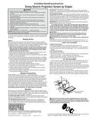
Installation/Operating Instructions<br />
<strong>Baronet</strong>/<strong>HW</strong> <strong>110V</strong> <strong>and</strong> <strong>220V</strong> <strong>Electric</strong> <strong>Projection</strong> <strong>Screen</strong> by <strong>Draper</strong><br />
These Installation/Operating Instructions are available in the official language<br />
of the country where you purchase the product. Please contact your<br />
distributor to request a copy.<br />
Vous pourriez dem<strong>and</strong>er les instructions d’installation et d’opération traduises<br />
dans la langue officielle du pays ou vous achetez le produit. Veuillez<br />
dem<strong>and</strong>er à votre distributeur.<br />
Die Gebrauchsanweisung für Installation und Konstruktion sind in der<br />
offiziellen Sprache des L<strong>and</strong>es, indem Sie das Produkt gekauft haben,<br />
vorh<strong>and</strong>en. Fragen Sie die jeweilige Verkaufs-Abteilung.<br />
Caution<br />
Read instructions through completely before proceeding.<br />
Follow instructions carefully. Installation contrary to instructions invalidates<br />
warranty.<br />
<strong>Screen</strong> should be accessible for complete removal should fabric become<br />
damaged or should other service be required.<br />
<strong>Screen</strong> should be installed level (using a carpenter’s level).<br />
Nothing should be fastened to screen dowel or viewing surface.<br />
Operating switch(es) packed separately in screen carton. Do not discard<br />
with packing material.<br />
<strong>Screen</strong> operates on 110-120V AC, 60 Hz. or <strong>220V</strong> AC, 50 Hz. or 60 Hz.<br />
current, depending on model ordered.<br />
NOTE: <strong>Screen</strong> has been thoroughly inspected <strong>and</strong> tested at factory <strong>and</strong><br />
found to be operating properly prior to shipment.<br />
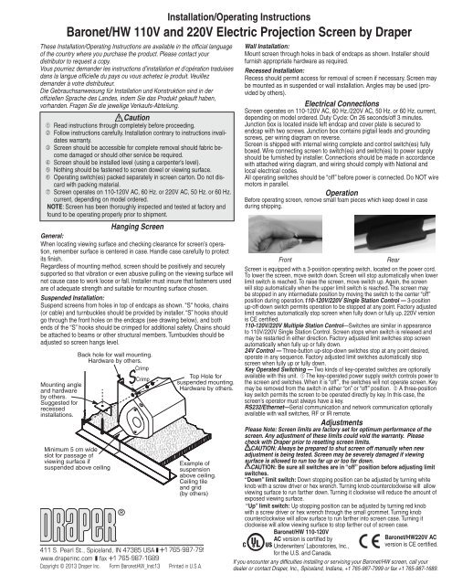
Hanging <strong>Screen</strong><br />
General:<br />
When locating viewing surface <strong>and</strong> checking clearance for screen’s operation,<br />
remember surface is centered in case. H<strong>and</strong>le case carefully to protect<br />
its finish.<br />
Regardless of mounting method, screen should be positively <strong>and</strong> securely<br />
supported so that vibration or even abusive pulling on the viewing surface will<br />
not cause case to work loose or fall. Installer must insure that fasteners used<br />
are of adequate strength <strong>and</strong> suitable for mounting surface chosen.<br />
Suspended Installation:<br />
Suspend screens from holes in top of endcaps as shown. "S" hooks, chains<br />
(or cable) <strong>and</strong> turnbuckles should be provided by installer. “S” hooks should<br />
go through the front holes on the endcaps (see drawing below), <strong>and</strong> both<br />
ends of the “S” hooks should be crimped for additional safety. Chains should<br />
be attached to beams or other structural members. Turnbuckles should be<br />
adjusted so screen hangs level.<br />
Mounting angle<br />
<strong>and</strong> hardware<br />
by others.<br />
Suggested for<br />
recessed<br />
installations.<br />
Back hole for wall mounting.<br />
Hardware by others.<br />
Crimp<br />
Minimum 5 cm wide<br />
slot for passage of<br />
viewing surface if<br />
suspended above ceiling<br />
®<br />
Crimp<br />
Example of<br />
suspension<br />
above ceiling.<br />
Ceiling tile<br />
<strong>and</strong> grid<br />
(by others)<br />
Copyright © 2013 <strong>Draper</strong> <strong>Inc</strong>. Form <strong>Baronet</strong><strong>HW</strong>_Inst13 Printed in U.S.A.<br />
Top Hole for<br />
suspended mounting.<br />
Hardware by others.<br />
Wall Installation:<br />
Mount screen through holes in back of endcaps as shown. Installer should<br />
furnish appropriate hardware as required.<br />
Recessed Installation:<br />
Recess should permit access for removal of screen if necessary. <strong>Screen</strong> may<br />
be mounted as in suspended or wall installation. Angles may be used (provided<br />
by others).<br />
<strong>Electric</strong>al Connections<br />
<strong>Screen</strong> operates on 110-120V AC, 60 Hz./<strong>220V</strong> AC, 50 Hz. or 60 Hz. current,<br />
depending on model ordered. Duty Cycle: On 26 seconds/off 3 minutes.<br />
Junction box is located inside left endcap <strong>and</strong> cover plate is secured to<br />
endcap with two screws. Junction box contains pigtail leads <strong>and</strong> grounding<br />
screws, per wiring diagram on reverse.<br />
<strong>Screen</strong> is shipped with internal wiring complete <strong>and</strong> control switch(es) fully<br />
boxed. Wire connecting screen to switch(es) <strong>and</strong> switch(es) to power supply<br />
should be furnished by installer. Connections should be made in accordance<br />
with attached wiring diagram, <strong>and</strong> wiring should comply with National <strong>and</strong><br />
local electrical codes.<br />
All operating switches should be “off” before power is connected. Do NOT wire<br />
motors in parallel.<br />
Operation<br />
Before operating screen, remove small foam pieces which keep dowel in case<br />
during shipping.<br />
Front<br />
<strong>Screen</strong> is equipped with a 3-position operating switch, located on the power cord.<br />
To lower the screen, move switch down. <strong>Screen</strong> will stop automatically when lower<br />
limit switch is reached. To raise the screen, move switch up. Again, the screen<br />
will stop automatically when the upper limit switch is reached. The screen may<br />
be stopped in any intermediate position by moving the switch to the center “off”<br />
position during operation.110-120V/<strong>220V</strong> Single Station Control — 3-position<br />
up-off-down switch permits operation to be stopped at any point. Factory adjusted<br />
limit switches automatically stop screen when fully down or fully up. <strong>220V</strong> version<br />
is CE certified.<br />
110-120V/<strong>220V</strong> Multiple Station Control—Switches are similar in appearance<br />
to <strong>110V</strong>/<strong>220V</strong> Single Station Control. <strong>Screen</strong> stops when switch is released <strong>and</strong><br />
may be restarted in either direction. Factory adjusted limit switches stop screen<br />
automatically when fully up or fully down.<br />
24V Control — Three-button up-stop-down switches stop at any point desired,<br />
operate in any sequence. Factory adjusted limit switches automatically stop<br />
screen when fully up or fully down.<br />
Key Operated Switching — Two kinds of key-operated switches are optionally<br />
available with this unit. The key-operated power supply switch controls power to<br />
the screen <strong>and</strong> switches. When it is “off”, the switches will not operate screen. Key<br />
may be removed from the switch in either “on” or “off” position. A three-position<br />
key switch permits the screen to be operated directly by key. In this case, the<br />
screen’s operator must always have a key.<br />
RS232/Ethernet—Serial communication <strong>and</strong> network communication optionally<br />
available with wall switches, RF or IR remote.<br />
Adjustments<br />
Please Note: <strong>Screen</strong> limits are factory set for optimum performance of the<br />
screen. Any adjustment of these limits could void the warranty. Please<br />
check with <strong>Draper</strong> prior to resetting screen limits.<br />
CAUTION: Always be prepared to shut screen off manually when new<br />
adjustment is being tested. <strong>Screen</strong> may be severely damaged if viewing<br />
surface is allowed to run too far up or too far down.<br />
CAUTION: Be sure all switches are in “off” position before adjusting limit<br />
switches.<br />
“Down” limit switch: Down stopping position can be adjusted by turning white<br />
knob with a screw driver or hex wrench. Turning knob counterclockwise will allow<br />
viewing surface to run farther down. Turning it clockwise will reduce the amount of<br />
exposed viewing surface.<br />
“Up” limit switch: Up stopping position can be adjusted by turning red knob<br />
with a screw driver or hex wrench through the small grommet. Turning knob<br />
counterclockwise will allow surface to run farther into screen case. Turning it<br />
clockwise will allow viewing surface to stop farther out of screen case.<br />
<strong>Baronet</strong>/<strong>HW</strong> 110-120V<br />
AC version is certified by<br />
Underwriters’ Laboratories, <strong>Inc</strong>.,<br />
for the U.S. <strong>and</strong> Canada.<br />
Rear<br />
<strong>Baronet</strong>/<strong>HW</strong><strong>220V</strong> AC<br />
version is CE certified.<br />
If you encounter any difficulties installing or servicing your <strong>Baronet</strong>/<strong>HW</strong> screen, call your<br />
dealer or contact <strong>Draper</strong>, <strong>Inc</strong>., Spicel<strong>and</strong>, Indiana, +1 765-987-7999 or fax +1 765-987-1689.
STOP<br />
STOP<br />
<strong>Baronet</strong>/<strong>HW</strong> by <strong>Draper</strong> Page 2 of 2<br />
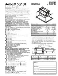
3¼"<br />
(83 mm)<br />
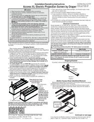
Case Dimensions<br />
Fabric width + 5¾" (146 mm)<br />
3¾"<br />
96 mm<br />
3¼"<br />
(83 mm)<br />
Viewing<br />
Surface<br />
Please Note: Do not wire motors in parallel.<br />
Single Station Control<br />
Junction box at<br />
left end of screen<br />
Internal <strong>Screen</strong> Wiring<br />
White (Common)<br />
Black (Down)<br />
Red (Up)<br />
Green (Motor Ground)<br />
Control<br />
switch Single gang box by others<br />
Blue Min. 4" x 2-1/8" x 1-7/8" deep<br />
Red<br />
Black<br />
Dashed wiring<br />
by electrician<br />
Location of key<br />
operated on-off<br />
switch if furnished<br />
To <strong>110V</strong> AC Line<br />
<strong>Baronet</strong>/<strong>HW</strong> <strong>110V</strong> AC<br />
Multiple Station Control<br />
Junction box at<br />
left end of screen<br />
Red<br />
Red<br />
Red<br />
Black<br />
Black<br />
Internal <strong>Screen</strong> Wiring<br />
White (Common)<br />
Black (Down)<br />
Red (Up)<br />
Green (Motor Ground)<br />
Blue<br />
Blue<br />
Blue<br />
Dashed wiring<br />
by electrician<br />
Wiring Diagrams<br />
Cap off with wire<br />
nut <strong>and</strong> tape<br />
Black Single gang box by others<br />
Min. 4" x 2-1/8" x 1-7/8" deep.<br />
3 shown. More or less equally<br />
feasible.<br />
Location of key<br />
operated on-off<br />
switch if furnished<br />
To <strong>110V</strong> AC Line<br />
Low Voltage, IR Remote or RF Remote (LVC-III)<br />
White or Blue-Common to screen & 110/<strong>220V</strong> AC Neutral<br />
Red-to screen (directional)<br />
Brown-to screen (directional)<br />
Yellow-to 110/<strong>220V</strong> AC-Hot<br />
Black-to 110/<strong>220V</strong> AC-Hot<br />
Green/Yellow (Ground)<br />
Dashed wiring by electrician<br />
Low voltage wiring by others<br />
Eye Port for IR Eye, RF Receiver or LED<br />
Wall Switch. For more than one of<br />
these, a splitter is required.<br />
3 Button Wall Switch<br />
DOWN - Black<br />
COM - White<br />
UP - Red<br />
Aux Port for connecting additional LVC-III<br />
modules (up to six total can be linkedconnect<br />
from Aux to Eye).<br />
110-120V 3-Position Wall Switch<br />
7 mm (2 3/4")<br />
Control<br />
Switches<br />
24v DC<br />
Internal <strong>Screen</strong> Wiring<br />
White/Blue (Common)<br />
Red 110/Black 220 (Up)<br />
Black 110/Brown 220 (Down)<br />
Green/Yellow<br />
(Motor Ground)<br />
To<br />
110/<strong>220V</strong><br />
Line<br />
Location of key<br />
operated on-off<br />
switch if furnished<br />
Control<br />
switch<br />
Dashed wiring<br />
by installer<br />
<strong>Baronet</strong>/<strong>HW</strong> <strong>220V</strong> AC (CE)<br />
Single Station Control<br />
Junction box at CE Approved<br />
left end of screen<br />
Internal <strong>Screen</strong> Wiring<br />
Blue-220v (Common)<br />
Brown-220v (Down)<br />
Black-220v (Up)<br />
Green/Yellow (Motor Ground)<br />
Neutral<br />
L1<br />
220v,<br />
50 Hz.<br />
or 60 Hz.<br />
Junction box at<br />
left end of screen<br />
Neutral<br />
Hot<br />
Multiple Station Control<br />
Not CE Approved<br />
Red<br />
Black<br />
Red<br />
Black<br />
Red<br />
220v, 50 Hz. or 60 Hz.<br />
MC1<br />
Black<br />
Internal <strong>Screen</strong> Wiring<br />
Blue-220v (Common)<br />
Brown-220v (Down)<br />
Black-220v (Up)<br />
Green/Yellow (Motor Ground)<br />
Cap off with wire<br />
nut & tape<br />
Blue<br />
Blue<br />
Blue<br />
Dashed wiring<br />
by installer<br />
See separate Serial Communication-RS232 Instruction sheet for<br />
enabling RS232 with the MC1.<br />
Fuse<br />
Program LED<br />
MC1<br />
White or Blue-Common<br />
Red-to <strong>Screen</strong> (directional)<br />
Black-to <strong>Screen</strong> (directional)<br />
Brown-Hot to AC<br />
Green/Yellow-Ground<br />
Low Voltage Wiring by others<br />
AC Wiring by electrician<br />
RS232 Data FROM Control System<br />
RS232 Data TO Control System<br />
Signal Ground & Manual Switch Common<br />
Manual Switch Down<br />
Manual Switch Up<br />
Eye Port for IR Eye. For RF Receiver or LED<br />
Wall Switch, a Splitter <strong>and</strong> a Power Supply<br />
is required. Plug RF Receiver or LED Wall<br />
Switch <strong>and</strong> Power Supply into splitter, then<br />
run cable from Splitter to MC1 Eye Port.<br />
To AC Line<br />
Internal <strong>Screen</strong> Wiring<br />
White/Blue (Common)<br />
Red 110/Black 220 (Up)<br />
Black 110/Brown 220 (Down)<br />
Green <strong>110V</strong>/<br />
Green/Yellow <strong>220V</strong><br />
(Motor Ground)<br />
Location of key<br />
operated on-off<br />
switch if furnished<br />
<strong>220V</strong> 3-Position, Surface Mount Wall Switch<br />
3.8 cm (1 1/2")<br />
3.5 cm (1 3/4")<br />
3.2 cm (1 1/4")<br />
UP<br />
3"-6" leads<br />
11.8 mm<br />
(4 1/2")<br />
8.6 cm<br />
(3 3/8")<br />
7.8 cm<br />
(3 1/16")<br />
DOWN<br />
www.draperinc.com (765) 987-7999