WR Spec 0,9/1,35 GB - Maybury Material Handling
WR Spec 0,9/1,35 GB - Maybury Material Handling
WR Spec 0,9/1,35 GB - Maybury Material Handling

You also want an ePaper? Increase the reach of your titles
YUMPU automatically turns print PDFs into web optimized ePapers that Google loves.
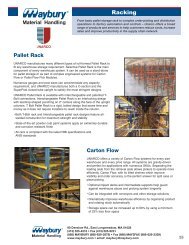
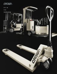
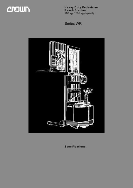
Heavy Duty Pedestrian<br />
Reach Stacker<br />
900 kg, 1<strong>35</strong>0 kg capacity<br />
Series <strong>WR</strong><br />
<strong>Spec</strong>ifications
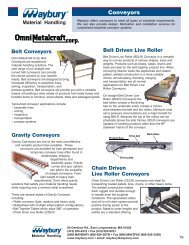
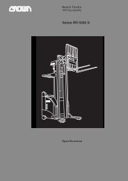
<strong>WR</strong> Heavy Duty Pedestrian<br />
Reach Stacker<br />
Series <strong>WR</strong><br />
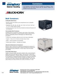
90°<br />
100<br />
4.21<br />
4.25<br />
4.26 3.7 4.21<br />
100<br />
100<br />
4.<strong>35</strong><br />
4.33/4.34<br />
100<br />
1.6<br />
1220<br />
Q<br />
7°<br />
4.20 4.28 4.22<br />
3°<br />
brake position<br />
drive<br />
position<br />
4.4 4.5<br />
4.2<br />
1.8<br />
4.9<br />
brake<br />
position<br />
940<br />
4.3<br />
4.31/4.32 125 4.15<br />
124<br />
210<br />
1.9<br />
4.37<br />
4.19
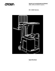
<strong>Spec</strong>ifications Series <strong>WR</strong><br />
Misc. Motors Performance Dimensions Tyres General Information<br />
1.1 Manufacturer Crown Equipment Corporation<br />
1.2 Model <strong>WR</strong>TL <strong>WR</strong>TF <strong>WR</strong>TT<br />
1.3 Prime Mover electric electric electric<br />
1.4 Operator Type walkie walkie walkie<br />
1.5 Load Capacity Q t 0.9 0.9 0.9<br />
1.6 Load Centre c mm 600 600 600<br />
1.8 Load Distance w. tilt / w. o. tilt x mm 395 / 452 395 / 452 422 / 480<br />
1.9 Wheel Base y mm 1168* 1168* 1250*<br />
2.1 Weight less battery kg 1345, 1395, 1480 1380, 1430, 1510 1640<br />
3.1 Tyre Type rubber / polyurethane rubber / polyurethane rubber / polyurethane<br />
3.2 Wheel Size front mm Ø 340 x 140 Ø 340 x 140 Ø 340 x 140<br />
3.3 Wheel Size rear mm Ø 125 x 70 Ø 125 x 70 Ø 125 x 70<br />
3.5 Wheels, number (x = driven) front/rear 1 x / 4 1 x / 4 1 x / 4<br />
3.6 Track Width front b10 mm drive unit central drive unit central drive unit central<br />
3.7 Track width rear b11 mm 965 – 1365 965 – 1365 965 – 1365<br />
4.1 Forkcarriage Tilt forwards / backwards ° angle 3 / 7 3 / 7 3 / 7<br />
4.2 Mast collapsed height h1 mm 1805, 2110, 2415 1805, 2110, 2415 1805<br />
4.3 Free Lift w.o. load backrest h2 mm 305 915** ,1220** ,1525** 915**<br />
4.4 Lift Height h3 mm 2590, 3200, 3810 2590,3200,3810 3860<br />
4.5 Mast extended height, w.o. load backrest** h4 mm 3495, 4105, 4715 3495, 4105, 4715 4765<br />
4.9 Tiller Arm Height in drive position min. / max. h14 mm 825 / 1120 825 / 1120 825 / 1120<br />
4.10 Outrigger Height h8 mm 125 125 125<br />
4.15 Lowered Fork Height h13 mm 64 64 64<br />
4.19 Overall Length*** fork length 1100 mm w. tilt/w.o. tilt* l1 mm 2085 / 2025 2085 / 2025 2140 / 2140<br />
4.20 Headlength w. tilt / w.o. tilt* l2 mm 985 / 925 985 / 925 1040 / 985<br />
4.21 Overall Width front / rear b1/b2 mm 915 / 1065 – 1465<br />
4.22 Fork Dimensions thxwxl mm 40 x 100 x 800, 1000, 1100, 1220<br />
4.23 Fork Carriage ISO class 2A 2A 2A<br />
4.24 Fork Carriage Width incl. load backrest b3 mm 910 – 1070 and 1220<br />
4.25 Width Across Forks b5 mm 200 – 800 in 75 mm increments<br />
4.26 Inside Straddle b4 mm 865 – 1265 in 50 mm increments<br />
4.28 Reach l4 mm 610 610 610<br />
4.31 Ground Clearance with load below mast m1 mm 75 75 75<br />
4.32 Ground Clearance centre wheelbase m2 mm 50 50 50<br />
4.33 Working Aisle Width 1000x1200 traverse w.tilt/w.o.tilt* Ast mm 2440 / 2400 2440 / 2400 2500 / 2460<br />
4.34 Working AIsle Width 800x1200 length w.tilt / w.o.tilt* Ast mm 2540 / 2430 2540 / 2430 2540 / 2490<br />
4.<strong>35</strong> Turning Radius Wa mm 1380* 1380* 1465*<br />
4.37 Length over Outrigger l7 mm 1520* 1520* 1605*<br />
5.1 Travel Speed w. / w.o. load km/h 4.3 / 5.1 4.3 / 5.1 4.3 / 5.1<br />
5.2 Lift Speed w. / w.o. load m/s 0.18 / 0.28 0.13 / 0.28 0.15 / 0.28<br />
5.3 Lower Speed w. / w.o. load m/s 0.17 / 0,14 0.13 / 0,14 0.16 / 0.14<br />
5.4 Reach Speed w. / w.o. load m/s 0.2 / 0.2 0.2 / 0.2 0.2 / 0.2<br />
5.7 Max. Gradeability w. load % 10 10 10<br />
5.10 Service Brake mechanic mechanic mechanic<br />
6.1 Traction Motor 60 min rating kW 1.0 1.0 1.0<br />
6.2 Lift Motor 15% on time kW 3.3 3.3 3.3<br />
6.3 Max. Battery Box Size opt. 1 / opt. 2 lxwxh mm 168 x 890 x 590 / 333 x 806 x 590<br />
6.4 Battery Voltage nominal capacity 5h opt. 1/opt. 2 V/Ah 24 / 225 • 24 / 525 24 / 225 • 24 / 525 24 / 225 • 24 / 525<br />
6.5 Battery Weight min. / max. opt. 1 / opt. 2 kg 230/320•440/6<strong>35</strong> 230/320•440/6<strong>35</strong> 230/320•440/6<strong>35</strong><br />
8.1 Type of Controller resistor resistor resistor<br />
8.2 Available Working Pressure for Attachments bar 127 127 127<br />
8.3 Available Oilflow for Attachments l/min. 11.7 11.7 11.7<br />
*** Add 165 mm if Battery option 2 is used<br />
*** Subtract 330 mm from free lift of <strong>WR</strong>TF and <strong>WR</strong>TT models, and add 330 mm to extended height of all models<br />
if load backrest is required<br />
*** without reach
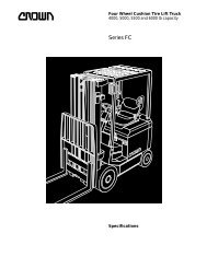
<strong>Spec</strong>ifications Series <strong>WR</strong><br />
Misc. Motors Performance Dimensions Tyres General Information<br />
1.1 Manufacturer Crown Equipment Corporation<br />
1.2 Model <strong>WR</strong>TL <strong>WR</strong>TF <strong>WR</strong>TT<br />
1.3 Prime Mover electric electric electric<br />
1.4 Operator Type walkie walkie walkie<br />
1.5 Load Capacity Q t 1.<strong>35</strong> 1.<strong>35</strong> 1.<strong>35</strong><br />
1.6 Load Centre c mm 600 600 600<br />
1.8 Load Distance w. tilt, w.o. tilt x mm 395 / 452 395 / 452 422 / 480<br />
1.9 Wheel Base y mm 1333 1333 1415<br />
2.1 Weight less battery kg 1345, 1395, 1480 1380, 1430, 1510 1640<br />
3.1 Tyre Type rubber / polyurethane rubber / polyurethane rubber / polyurethane<br />
3.2 Wheel Size front mm Ø 340 x 140 Ø 340 x 140 Ø 340 x 140<br />
3.3 Wheel Size rear mm Ø 125 x 70 Ø 125 x 70 Ø 125 x 70<br />
3.5 Wheels number (x = driven) front / rear 1 x / 4 1 x / 4 1 x / 4<br />
3.6 Track Width front b10 mm drive unit central drive unit central drive unit central<br />
3.7 Track width rear b11 mm 965 – 1365 965 – 1365 965 – 1365<br />
4.1 Forkcarriage Tilt forwards/backwards angle 3 / 7 3 / 7 3 / 7<br />
4.2 Mast collapsed height h1 mm 1805, 2110, 2415 1805, 2110, 2415 1805<br />
4.3 Free Lift w.o. load backrest h2 mm 305 915**, 1220**, 1525** 915**<br />
4.4 Lift Height h3 mm 2590, 3200, 3810 2590, 3200, 3810 3860<br />
4.5 Mast extended height, w.o. load backrest** h4 mm 3495, 4105, 4715 3495, 4105, 4715 4765<br />
4.9 Tiller Arm Height in drive position min. / max. h14 mm 825 / 1120 825 / 1120 825 / 1120<br />
4.10 Outrigger Height h8 mm 125 125 125<br />
4.15 Lowered Fork Height h13 mm 64 64 64<br />
4.19 Overall Length*** fork length 1100mm w. tilt/w.o. tilt* l1 mm 2250 / 2190 2250 / 2190 2305/2305<br />
4.20 Headlength w. tilt / w.o. tilt* l2 mm 1150 / 1090 1150 / 1090 1205 / 1150<br />
4.21 Overall Width front / rear b1/b2 mm 915 / 1065 - 1465<br />
4.22 Fork Dimensions thxwxl mm 40 x 100 x 800, 1000, 1100, 1220<br />
4.23 Fork Carriage ISO class 2A 2A 2A<br />
4.24 Fork Carriage Width incl. load backrest b3 mm 910 - 1070 and 1220<br />
4.25 Width Across Forks b5 mm 200 – 800 in 75 mm increments<br />
4.26 Inside Straddle b4 mm 865 – 1265 in 50 mm increments<br />
4.28 Reach l4 mm 610 610 610<br />
4.31 Ground Clearance with load below mast m1 mm 75 75 75<br />
4.32 Ground Clearance centre wheelbase m2 mm 50 50 50<br />
4.33 Working Aisle Width 1000x1200 traverse w.tilt/w.o.tilt* Ast mm 2600 / 2570 2600 / 2570 2670 / 2630<br />
4.34 Working AIsle Width 800 x 1200 length w.tilt / w.o.tilt* Ast mm 2700 / 2600 2700 / 2600 2700 / 2660<br />
4.<strong>35</strong> Turning Radius Wa mm 1545 1545 1630<br />
4.37 Length over Outrigger l7 mm 1685 1685 1770<br />
5.1 Travel Speed w. / w.o. load km/h 4.3 / 5.1 4.3 / 5.1 4.3 / 5.1<br />
5.2 Lift Speed w. / w.o. load m/s 0.13 / 0,21 0.14 / 0.21 0.15 / 0.21<br />
5.3 Lower Speed w. / w.o. load m/s 0.15 / 0.14 0.14 / 0.14 0.17 / 0.14<br />
5.4 Reach Speed w. / w.o. load m/s 0.2 / 0.2 0.2 / 0.2 0.2 / 0.2<br />
5.7 Max. Gradeability w. load % 10 10 10<br />
5.10 Service Brake mechanic mechanic mechanic<br />
6.1 Traction Motor 60 min rating kW 1.0 1.0 1.0<br />
6.2 Lift Motor 15% on time kW 3.3 3.3 3.3<br />
6.3 Max. Battery Box Size lxwxh mm 333 x 806 x 590 333 x 806 x 590 333 x 806 x 590<br />
6.4 Battery Voltage nominal capacity 5h V/Ah 24 / 600 24 / 600 24 / 600<br />
6.5 Battery Weight min. / max. kg 440 / 6<strong>35</strong> 440 / 6<strong>35</strong> 440 / 6<strong>35</strong><br />
8.1 Type of Controller resistor resistor resistor<br />
8.2 Available Working Pressure for Attachments bar 127 127 127<br />
8.3 Available Oilflow for Attachments l/min. 11.7 11.7 11.7<br />
*** Add 165 mm if Battery option 2 is used<br />
*** Subtract 330 mm from free lift of <strong>WR</strong>TF and <strong>WR</strong>TT models, and add 330 mm to extended height of all models<br />
if load backrest is required<br />
*** without reach
Series <strong>WR</strong><br />
Technical Information<br />
Standard Equipment<br />
1. Three speeds forward<br />
and reverse.<br />
2. Battery compartment<br />
rollers.<br />
3. Emergency power<br />
disconnect.<br />
4. Key switch.<br />
5. Horn.<br />
6. Safety shield.<br />
7. Polyurethane drive tyre.<br />
8. Polyurethane load<br />
wheels.<br />
9. Third-speed cutoff switch.<br />
10. SBE battery connector.<br />
11. Reversing button.<br />
12. Load backrest.<br />
13. Carriage tilt.<br />
Optional Equipment<br />
1. SCR speed control.<br />
2. Rubber drive tyre<br />
Ø 340 x 140 mm.<br />
3. Battery discharge<br />
indicator.<br />
4. Battery discharge<br />
indicator with lift lockout.<br />
5. Hour metre.<br />
6. Raise and lower buttons<br />
in control handle.<br />
7. Optional lift heights.<br />
8. Corrosion conditioning.<br />
9. Freezer conditioning.<br />
10. <strong>Spec</strong>ial paint.<br />
11. Power steering.<br />
Electrical System<br />
Standard equipment<br />
includes:<br />
1. 24 volt electrical system.<br />
2. Series wound high torque<br />
1.0 kW drive motor.<br />
3. Series wound high torque<br />
3.3 kW lift motor.<br />
4. Heavy duty pump<br />
contactor with replaceable<br />
tips.<br />
5. Four heavy duty travel<br />
speed contactors. A solidstate<br />
time relay provides<br />
controlled acceleration<br />
between 2nd and 3rd<br />
speed.<br />
6. Fused control and power<br />
circuits.<br />
7. Colour coded wiring for<br />
ease of service.<br />
8. Key switch.<br />
9. Power disconnect lever.<br />
Hydraulic System<br />
Standard equipment<br />
includes:<br />
1. Heavy duty motor and<br />
gear pump assembled as<br />
an integral unit. Pump and<br />
motor unit hinged for easy<br />
accessibility to electrical<br />
system.<br />
2. Spool-type hydraulic<br />
control valve with built-in<br />
check and relief valve.<br />
3. Pressure compensating<br />
flow control valve at base<br />
of lift cylinder regulates<br />
maximum lowering speed.<br />
4. Lift cylinder rams are hard<br />
chrome plated for smooth<br />
operation and increased<br />
life and are equipped<br />
with long-life polyurethane<br />
packings. Lift cylinders<br />
are designed to operate<br />
at optimum hydraulic<br />
pressure depending on<br />
capacity of truck. All<br />
<strong>WR</strong>TF and <strong>WR</strong>TT models<br />
are equipped with three<br />
cylinder cluster to provide<br />
full free lift.<br />
5. Movable oil reservoir<br />
permits easy accessibility<br />
to hydraulic system.<br />
6. Overload valve set to<br />
prevent lift when system<br />
reaches maximum<br />
pressure.<br />
7. Centrally located levers for<br />
raising, lowering, tilt, and<br />
reach are standard equipment.These<br />
throttles<br />
permit infinite control of<br />
fork positioning.<br />
Drive Unit<br />
Gear drive from motor to<br />
drive wheel axle. The gear<br />
train is mounted on ball and<br />
tapered roller bearings, and<br />
operates in an oil filled,<br />
sealed housing.<br />
Reach Mechanism<br />
Heavily constructed pantograph<br />
type reach mechanism<br />
extends 610 mm. Dual reach<br />
cylinders used on <strong>WR</strong>TL and<br />
<strong>WR</strong>TF units. Large single<br />
cylinder used on all triple<br />
telescopic units. Mechanism<br />
features: chrome plated<br />
cylinder rods, hydraulic<br />
cushions at both ends of<br />
stroke, lifetime-lubricated<br />
sealed channel roller<br />
bearings,anti-friction bearings<br />
at centre pivots, and selfaligning,<br />
grease lubricated<br />
spherical bearings.<br />
Tilt<br />
Carriage tilts 7° up and 3°<br />
down. Designed to operate in<br />
all reach positions and at all<br />
lifting heights.<br />
Brake<br />
Internal expanding mechanical<br />
brake with Ø 127 mm<br />
drum and bonded brake<br />
linings. Brake is applied<br />
when control handle is within<br />
15°of full vertical or full<br />
horizontal position.<br />
Power Unit Structure<br />
Hinged access doors permit<br />
easy entry to all electric and<br />
hydraulic components.<br />
Chassis is equipped with<br />
rollers for easy battery<br />
installation and removal.<br />
Lift Structure<br />
Outer and inner masts are<br />
constructed from hot rolled<br />
steel I - beam. Telescoping<br />
mast section nests in main<br />
upright to provide good<br />
visibility for operator.<br />
Control Handle<br />
Control handle has dual twistgrips<br />
which control three<br />
speeds forward and reverse.<br />
Twist-grips return to neutral<br />
when released. The handle<br />
contains a large safety button<br />
which reverses the direction<br />
of the truck should the button<br />
touch the operator. A large<br />
horn button is standard equipment,<br />
as is a third speed cutoff<br />
switch.<br />
Safety Switches<br />
1. Third speed switch in<br />
control handle may be<br />
used to shut off high speed<br />
when operating in<br />
congested areas.<br />
2. Limit switch automatically<br />
reduces maximum travel<br />
speed immediately upon<br />
extension of second and<br />
third stages on <strong>WR</strong>TF<br />
and <strong>WR</strong>TT models, and<br />
when forks extend above<br />
1727 mm on <strong>WR</strong>TL models.<br />
3. Reversing button on<br />
control handle reverses<br />
direction of travel when<br />
actuated by the operator.<br />
Safety Regulations<br />
Conforms to European safety<br />
standards.<br />
Dimensions and performance<br />
data given may vary due to<br />
manufacturing tolerances.<br />
Performance is based on an<br />
average size vehicle and is<br />
affected by weight, condition<br />
of truck, how it is equipped<br />
and the conditions of the<br />
operating area. Crown<br />
products and specifications<br />
are subject to change without<br />
notice.
European Manufacturing:<br />
Crown Gabelstapler GmbH<br />
Roding Germany<br />
VFS-<strong>WR</strong>-01-<strong>GB</strong> 10/94<br />
Printed in Germany<br />
Crown Equipment<br />
Galway, Ireland