1 Production of Chloramines and Chloramine ... - Save the Water
1 Production of Chloramines and Chloramine ... - Save the Water
1 Production of Chloramines and Chloramine ... - Save the Water

Create successful ePaper yourself
Turn your PDF publications into a flip-book with our unique Google optimized e-Paper software.
<strong>Production</strong> <strong>of</strong> <strong><strong>Chloramine</strong>s</strong> <strong>and</strong> <strong>Chloramine</strong> Monitoring in <strong>Water</strong> Supply Systems<br />
By Robert D. McVay PE<br />
Florida Rural <strong>Water</strong> Association<br />
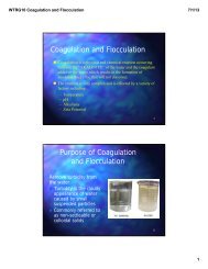
Abstract:<br />
The use <strong>of</strong> chorine <strong>and</strong> chloramine are well understood methods for disinfecting water.<br />
However, chloramine is a weaker disinfectant than chlorine <strong>and</strong> its use can be<br />
problematic if it is not properly formed <strong>and</strong> monitored. This paper examines <strong>the</strong> most<br />
critical considerations for <strong>the</strong> production <strong>and</strong> use <strong>of</strong> chloramine as a secondary<br />
disinfectant.<br />
Introduction:<br />
Source waters in many areas <strong>of</strong> <strong>the</strong> state contain elevated levels <strong>of</strong> TOC which combines<br />
with free chlorine to produce disinfection by-products (DBP). These compounds are<br />
regulated at 80 PPB <strong>and</strong> 60 PPB for total trihalomethanes <strong>and</strong> haloacetic acids. Meeting<br />
<strong>the</strong>se low regulatory limits when using free chlorine as a disinfectant can be difficult.<br />
With <strong>the</strong> increase in regulatory attention such as <strong>the</strong> new Initial Distribution System<br />
Evaluation (IDSE) that requires all public water supply systems to report critical DBP<br />
values, given problems meeting existing rules <strong>and</strong> now new rules, many water treatment<br />
systems have elected to switch to chloramines as <strong>the</strong>ir secondary disinfectant.<br />
Chloramination or producing chlorine by adding ammonia in <strong>the</strong> presence <strong>of</strong> free<br />
chlorine, has been used by many water treatment systems for a number <strong>of</strong> years. The<br />
process <strong>of</strong> forming chloramines is well understood <strong>and</strong> consists <strong>of</strong> adding ammonia in <strong>the</strong><br />
presence <strong>of</strong> free chlorine in a ratio <strong>of</strong> about 3 – 5 parts free chlorine to 1 part <strong>of</strong> ammonia.<br />
Unfortunately, when water systems switch from free chlorine to chloramine, it brings<br />
with it new <strong>and</strong> unexpected problems. Attempting to find an explanation for what is<br />
occurring is not easy, <strong>and</strong> when problems grow worse, <strong>the</strong> system operator is left with no<br />
o<strong>the</strong>r option than to switch back to free chlorine disinfection <strong>and</strong> perform a “burn.” A<br />
burn is a process where superchlorinating with free chlorine is used to destroy<br />
problematic organisms <strong>and</strong> unstable conditions in <strong>the</strong> water system. When this happens,<br />
disinfection byproducts <strong>of</strong>ten exceed regulatory limits.<br />
Fortunately, <strong>the</strong> use <strong>of</strong> chloramines <strong>and</strong> <strong>the</strong> control <strong>of</strong> problems in <strong>the</strong> distribution system<br />
follow predicable patterns that can be identified <strong>and</strong> corrected before conditions<br />
deteriorate to a point where a burn is needed. This paper examines <strong>the</strong> concepts in <strong>the</strong><br />
formation <strong>and</strong> <strong>the</strong> use <strong>of</strong> chloramines <strong>and</strong> suggests preemptive techniques to identify <strong>the</strong><br />
status <strong>of</strong> deteriorating conditions <strong>and</strong> implement corrective actions to keep <strong>the</strong><br />
chloramination process under control.<br />
1
Underst<strong>and</strong>ing Chlorine Addition for Primary Disinfection:<br />
Disinfection by-products are formed when chlorine in <strong>the</strong> form <strong>of</strong> hypochlorous acid<br />
formed in <strong>the</strong> disinfection process is allowed to contact naturally occurring organic<br />
material. To control <strong>the</strong> production <strong>of</strong> disinfection by-products effectively, three methods<br />
can be employed: 1.) remove <strong>the</strong> organic precursors that are reactive with <strong>the</strong> chlorine,<br />
2.) decrease <strong>the</strong> amount <strong>of</strong> hypochlorous acid available for <strong>the</strong> reaction <strong>and</strong> 3.) decrease<br />
<strong>the</strong> time <strong>of</strong> contact between <strong>the</strong> organic material <strong>and</strong> <strong>the</strong> hypochlorous acid. Generally,<br />
operators will accomplish all <strong>of</strong> <strong>the</strong>se objectives by moving chlorine dosing points to<br />
locations that allow some precursor removal to occur within <strong>the</strong> plant <strong>and</strong> <strong>the</strong>n lower free<br />
chlorine concentrations to only those levels needed to meet regulatory requirements.<br />
When in-plant strategies are not successful, many systems have chosen to reduce <strong>the</strong><br />
amount <strong>of</strong> hypochlorous acid available for reaction within <strong>the</strong> distribution system by<br />
switching to chloramine as a secondary disinfectant. Free chlorine is used to provide<br />
primary disinfection <strong>and</strong> meet initial chlorine dem<strong>and</strong> <strong>and</strong> chloramine is used as <strong>the</strong><br />
secondary disinfectant, i.e. in <strong>the</strong> distribution system.<br />
It is useful to review <strong>the</strong> mechanisms <strong>of</strong> how free chlorine <strong>and</strong> chloramines are made in<br />
<strong>the</strong> disinfection process. When free chlorine (Cl 2 ) is initially added to water it goes<br />
through a series <strong>of</strong> chemical actions <strong>and</strong> eventually splits into two components. These<br />
components are hypochlorous acid (<strong>the</strong> active compound that forms <strong>the</strong> disinfection byproducts)<br />
<strong>and</strong> <strong>the</strong> hypochlorite ion.<br />
Although both hyppchlorous acid <strong>and</strong> <strong>the</strong> hypochorite ion provide disinfection, <strong>the</strong><br />
hypochorous acid that is formed is much stronger than <strong>the</strong> ion. The amount <strong>of</strong><br />
hypochlorous acid or <strong>the</strong> hypochlorite ion formed, is completely dependant on pH. These<br />
relationships are shown below:<br />
Concentration <strong>of</strong> Hypochlorous<br />
Acid <strong>and</strong> Hypchlorite Ion vs pH<br />
HOCl<br />
OCl _<br />
As can be seen from <strong>the</strong> above curve, when <strong>the</strong> pH <strong>of</strong> <strong>the</strong> water is around 7.5, a value<br />
near most Florida ground waters, <strong>the</strong> relative concentrations <strong>of</strong> hypochlorous acid is<br />
around 50%. Thus if pH is lowered, more hypochlorous acid is available <strong>and</strong> more DBPs<br />
form at a faster rate. Conversely, when pH is increased <strong>the</strong> available hypochlorous acid is<br />
2
lower <strong>and</strong> DBP formation will be slower. As <strong>the</strong> pH approaches 8, <strong>the</strong> relative portion <strong>of</strong><br />
<strong>the</strong> hypochlorous acid is about 20%. Above a pH <strong>of</strong> 9, most all <strong>of</strong> <strong>the</strong> chlorine is in <strong>the</strong><br />
form <strong>of</strong> <strong>the</strong> less effective hypochlorite ion <strong>and</strong> disinfectant ability will be about 1% <strong>of</strong> <strong>the</strong><br />
disinfectant power compared to <strong>the</strong> acid form. Raising pH does have a significant<br />
drawback <strong>and</strong> that is that as <strong>the</strong> amount <strong>of</strong> hypochlorous acid is reduced disinfection<br />
ability is reduced accordingly.<br />
The practical significance <strong>of</strong> this in water treatment is that free chlorine residual does not<br />
indicate microbial inactivation unless pH is accounted for. This limitation can be avoided<br />
when <strong>the</strong> hypochlorous acid component is directly measured. This can be accomplished<br />
by <strong>the</strong> use <strong>of</strong> an ORP meter. An ORP meter will provide an estimate <strong>of</strong> <strong>the</strong> inactivation<br />
power <strong>of</strong> chlorine at any given pH. A ORP value <strong>of</strong> 650 mV has been used since<br />
mid-1980 for municipal drinking water in Europe for water quality. The arrow below<br />
shows how this value relates to current DEP st<strong>and</strong>ards. At ORP values between 500 <strong>and</strong><br />
600 mV bacterial activation will occur but only after much longer contact times.<br />
Breakpoint Chlorination Curve <strong>and</strong> <strong>Chloramine</strong> Development<br />
To underst<strong>and</strong> how chlorine forms disinfection by-products with a source water that<br />
contains chlorine dem<strong>and</strong>ing substances we need to develop a breakpoint chlorination<br />
curve as shown below. The X-axis shows <strong>the</strong> amount <strong>of</strong> free chlorine that is being<br />
3
continuously added. The Y-axis shows <strong>the</strong> total chlorine residual that is measured. Total<br />
chlorine is in a combined form (Y axis) until all <strong>the</strong> inorganic <strong>and</strong> organic dem<strong>and</strong> is<br />
satisfied, in o<strong>the</strong>r words until <strong>the</strong> initial inorganic <strong>and</strong> organic dem<strong>and</strong> has been satisfied,<br />
no hypochlorous acid is available. For each source water <strong>the</strong> breakpoint curve will be<br />
unique but it will follow <strong>the</strong> general pattern shown below.<br />
Note that between <strong>the</strong> segments labeled 1 <strong>and</strong> 2, although free chlorine has been added,<br />
no chlorine residual <strong>of</strong> any kind is shown on <strong>the</strong> left Y-axis. This is because within this<br />
range <strong>the</strong> chlorine is reacting with inorganic constituents in <strong>the</strong> water such as iron,<br />
manganese, hydrogen sulfide <strong>and</strong> any ammonia that may be naturally present. This<br />
oxidation-reduction reaction will proceed to completion until all inorganic substrate is<br />
consumed. What is important to note here is, that no reaction with organic materials<br />
present in <strong>the</strong> water will take place until all <strong>the</strong> inorganic dem<strong>and</strong> has been satisfied.<br />
Within this range, free chlorine may be added to <strong>the</strong> water without producing any<br />
significant disinfection byproducts. This concept is important because many Florida<br />
water sources contain iron, hydrogen sulfide <strong>and</strong> background ammonia all inorganic<br />
dem<strong>and</strong>ing substances.<br />
Between segments 2 <strong>and</strong> 3, <strong>the</strong>re is no longer any un-reacted inorganic compounds in <strong>the</strong><br />
water <strong>and</strong> oxidation <strong>of</strong> organic contaminants that produce disinfection by-products will<br />
now occur. To prevent this undesirable situation from occurring, many water treatment<br />
plants with disinfection byproduct problems have switched to <strong>the</strong> use <strong>of</strong> chloramines.<br />
<strong>Chloramine</strong> is produced by adding ammonia, in a ratio <strong>of</strong> between 3 to 5 parts measured<br />
as free chlorine to 1 part ammonia. If chlorine is added at a higher ratio, <strong>the</strong>n <strong>the</strong><br />
chloramine will transition from <strong>the</strong> monochloramine form to <strong>the</strong> dichloramine form as<br />
shown past point 3 on <strong>the</strong> curve. Note that <strong>the</strong>se ratios apply only after inorganic chlorine<br />
dem<strong>and</strong> has been satisfied. This is why it is important for plants to develop <strong>the</strong>ir unique<br />
breakpoint chlorination curves.<br />
4
It is important that <strong>the</strong> chlorine be added prior to <strong>the</strong> ammonia. Ammonia is a nutrient<br />
<strong>and</strong> adding it to a water prior to <strong>the</strong> chlorine will encourage biological growth <strong>and</strong><br />
bacterial resistance to disinfection.<br />
When ammonia is added to water containing hypochlorous acid, <strong>the</strong> production <strong>of</strong><br />
chloramines occurs instantaneously with <strong>the</strong> rate <strong>of</strong> reaction controlled by pH. The<br />
reaction rates are shown in <strong>the</strong> following table. The arrow indicates <strong>the</strong> range <strong>of</strong> Florida<br />
source waters that are typically between a pH <strong>of</strong> 6.8 to 7.8. As can be seen, in this range<br />
chloramine production is instantaneous.<br />
Determining Chlorine Dem<strong>and</strong> for Your <strong>Water</strong> System<br />
It is imperative that water systems identify <strong>the</strong>ir chlorine dem<strong>and</strong> so that free chlorine<br />
dosage can be minimized at <strong>the</strong> plant <strong>and</strong> to ensure chlorine residuals can be maintained<br />
in <strong>the</strong> distribution system at <strong>the</strong> 0.20 mg/l free chlorine or 0.60 mg/l chloramine levels<br />
that are regulatory requirements.<br />
Many systems that have performed DBP analysis on <strong>the</strong>ir finished water at <strong>the</strong> plant, find<br />
that after implementing <strong>the</strong> controls described above, that DBP produced at <strong>the</strong> plant are<br />
25% or less than those produced in <strong>the</strong> distribution system. By maintaining excessive free<br />
chlorine residuals in <strong>the</strong> distribution system, <strong>the</strong> reaction rates with organic material will<br />
be increased <strong>and</strong> more disinfection by-products will be produced. Conversely with<br />
chloramine, if significant excess residual is not maintained, <strong>the</strong> chloramine will have a<br />
tendency to breakdown leading to formation <strong>of</strong> disinfection by-products, slime growth<br />
<strong>and</strong> nitrification. It is important that systems check <strong>the</strong> concentration both at <strong>the</strong> entrance<br />
to <strong>the</strong> distribution system <strong>and</strong> at <strong>the</strong> regulatory monitoring point for purposes <strong>of</strong> targeting<br />
<strong>the</strong> most significant problems.<br />
The substances that cause disinfectant dem<strong>and</strong> are indicative <strong>of</strong> <strong>the</strong> source water quality<br />
<strong>and</strong> are also are <strong>the</strong> compounds that typically cause water quality customer complaints.<br />
Most source waters contain a variety <strong>of</strong> both inorganic <strong>and</strong> organic contaminants whose<br />
chlorine dem<strong>and</strong> can be identified with a simple jar test without knowledge <strong>of</strong> <strong>the</strong> types<br />
<strong>of</strong> concentrations <strong>of</strong> <strong>the</strong> contaminants. The procedures illustrated below can be quickly<br />
set up <strong>and</strong> used to give a good approximation <strong>of</strong> <strong>the</strong> chlorine dem<strong>and</strong>. Limiting free<br />
chlorine dem<strong>and</strong> to that necessary to maintain <strong>the</strong> required residual is <strong>the</strong> most effective<br />
method <strong>of</strong> controlling disinfection by-product production.<br />
5
1. Use <strong>of</strong> a Laboratory Jar Test Method for Plotting a Chlorine Dem<strong>and</strong> Curve<br />
Step 1: Determine Stock Chlorine Solution by adding about 10 ml <strong>of</strong> common bleach or<br />
a known concentration <strong>of</strong> chlorine solution used at <strong>the</strong> plant. Make up 1 liter using<br />
deionized water to a dilution that is around 500 ppm. This is accomplished by adding 10<br />
ml <strong>of</strong> household bleach to 990 ml <strong>of</strong> distilled water.<br />
Step 2: The actual concentration <strong>of</strong> <strong>the</strong> stock solution can be estimated using a DPD<br />
meter. The accuracy will be + 0.1 mg/l which is not significant in source waters where<br />
well changes are frequent. Convert <strong>the</strong> St<strong>and</strong>ard Solution into a chlorine concentration<br />
that is a whole number. This step is not necessary but makes fur<strong>the</strong>r dilutions used for<br />
plotting <strong>the</strong> dem<strong>and</strong> curve easier.<br />
Making Dilutions from a<br />
St<strong>and</strong>ard<br />
1 L<br />
Make Stock solution from 5.25% chlorine<br />
solution in a one liter (1000 ml) container<br />
Initial Contains ~ 52,500 ppm<br />
Add 10 ml bleach <strong>and</strong> fill to 1 liter point<br />
Determining Dilution<br />
10 ml<br />
500 PPM<br />
Determine Dose Std<br />
10 ml = 10/1000 = 0.01<br />
0.01 x 52,500 = 525<br />
990 ml<br />
525<br />
PPM<br />
50 ml<br />
950 ml<br />
5.0/5.25 = 0.95<br />
5% x 1000 ml = 50 ml<br />
Step 3: Begin adding chlorine to a 1 liter source water sample 5 ml at a time <strong>and</strong> record<br />
<strong>the</strong> Total Chlorine Residual <strong>and</strong> Free Chlorine Residual using a DPD meter. The chlorine<br />
contact time should be approximately <strong>the</strong> same as in <strong>the</strong> plant. Allow about 15 minutes<br />
for <strong>the</strong> reactions to occur or use <strong>the</strong> known reaction time if known.<br />
6
Determining Dose Rates from<br />
Stock Solution<br />
Jar #<br />
1<br />
2<br />
3<br />
4<br />
Adding Stock Solution to Determine Dose<br />
for 1 Liter Container <strong>of</strong> <strong>Water</strong><br />
Dose Calculations<br />
Amount<br />
Added<br />
5 ml<br />
10 ml<br />
15 ml<br />
20 ml<br />
Dose<br />
1 ppm<br />
2 ppm<br />
3 ppm<br />
4 ppm<br />
Std<br />
Sample<br />
Step 4. After each chlorine dose <strong>and</strong> detention, measure both total <strong>and</strong> free chlorine<br />
residual with a DPD meter. Subtract <strong>the</strong> Free from <strong>the</strong> Total to determine <strong>the</strong> amount <strong>of</strong><br />
combined chlorine. From <strong>the</strong> data compiled, plot <strong>the</strong> total chlorine residual vs. dose<br />
which will produce <strong>the</strong> st<strong>and</strong>ard chlorine breakpoint curve for your water treatment<br />
system. If you want to increase <strong>the</strong> accuracy, bracket your results <strong>and</strong> repeat <strong>the</strong> test. For<br />
example if <strong>the</strong> curve requires more refinement to better observe results, you can add<br />
doses in 1 ml increments instead <strong>of</strong> <strong>the</strong> 5 ml increments, etc.<br />
Performing a Chlorine Dem<strong>and</strong><br />
Jar Test<br />
10 ml<br />
20 ml<br />
30 ml<br />
40 ml<br />
Use<br />
1- liter samples<br />
added<br />
added<br />
added<br />
added<br />
Note: Combined = Total - Free<br />
Results <strong>of</strong> Chlorine Test<br />
Sample # Total Free Combined<br />
1<br />
2<br />
3<br />
Record Total<br />
<strong>and</strong> Free Chlorine<br />
4<br />
Plot Results<br />
Total Chlorine – Free Chlorine = Combined Chlorine.<br />
7
The chlorine dem<strong>and</strong> test will provide <strong>the</strong> operator with a good estimate <strong>of</strong> <strong>the</strong> chlorine<br />
dem<strong>and</strong>ing substances that are immediately available <strong>and</strong> provide <strong>the</strong> minimum chlorine<br />
dose that can be added to achieve breakpoint. This is important because if excessive<br />
chlorine is being added, this will result in increasing <strong>the</strong> production <strong>of</strong> disinfection byproducts<br />
within <strong>the</strong> treatment plant. CT tables published by DEP can be used as a guide<br />
for limiting excessive free chlorine residual concentrations.<br />
2. Estimating Chlorine Dem<strong>and</strong> Using Known Concentrations <strong>of</strong> Contaminants<br />
The chlorine dem<strong>and</strong> curve produced above should closely match <strong>the</strong> calculated chlorine<br />
dem<strong>and</strong> from <strong>the</strong> laboratory values that identify <strong>the</strong> chlorine dem<strong>and</strong>ing substances. The<br />
method for computing chlorine dem<strong>and</strong> is illustrated below.<br />
Step 1: Determine <strong>the</strong> amount <strong>of</strong> Iron, Manganese, Hydrogen Sulfide, Ammonia,<br />
Organic Nitrogen, Nitrite <strong>and</strong> TOC in your source water. Place <strong>the</strong> values in a table <strong>and</strong><br />
use <strong>the</strong> multiplication factors shown below to determine your chlorine dem<strong>and</strong> as shown<br />
in <strong>the</strong> example below.<br />
Example: A source water has <strong>the</strong> following chemical contaminants:<br />
Chemical Source <strong>Water</strong> #1 Source <strong>Water</strong> #2<br />
Fe 0.3 mg/l 0.30 mg/l<br />
Mn 0.06 mg/l 0.06 mg/l<br />
H 2 S 0.2 mg/l 1.5 mg/l<br />
NO 2 0.1 mg/l 0.1 mg/l<br />
NH 3 0.1 mg/l 1.4 mg/l<br />
Org-N 0.05 mg/l 0.05 mg/l<br />
TOC 2.0 mg/l 6.0 mg/l<br />
Step2: Determine Chlorine Dem<strong>and</strong> using multipliers shown.<br />
Determining Chemical Dem<strong>and</strong> from Source <strong>Water</strong> Analysis<br />
Chemical<br />
Constituent<br />
(mg/l)<br />
Source<br />
<strong>Water</strong><br />
#1<br />
Source<br />
<strong>Water</strong><br />
#2<br />
Multiplier<br />
Source<br />
<strong>Water</strong><br />
#1<br />
Source<br />
<strong>Water</strong><br />
#2<br />
Fe 0.30 0.30 0.64 0.19 0.19<br />
Mn 0.06 0.06 1.3 0.08 0.08<br />
H2S 0.20 1.5 2 0.40 3.00<br />
NO2 0.10 0.10 5 0.50 0.50<br />
NH3 0.10 1.4 12 1.20 16.80<br />
Org-N 0.005 0.005 1 0.01 0.01<br />
TOC 2.0 6.0 0.1 0.20 0.60<br />
Total 2.58 21.18<br />
8
This method provide a quick check on <strong>the</strong> chlorine dem<strong>and</strong>ing substances. Note that <strong>the</strong><br />
dem<strong>and</strong> exerted by very small concentrations <strong>of</strong> naturally occurring ammonia is<br />
extremely high <strong>and</strong> will dominate <strong>the</strong> dem<strong>and</strong> for free chlorine. Also note that <strong>the</strong><br />
dem<strong>and</strong> for organic substances is typically less than 10% <strong>of</strong> <strong>the</strong> dem<strong>and</strong> total.<br />
<strong>Chloramine</strong> Sag with Additional Free Chlorine Addition<br />
The examples provided above refer to <strong>the</strong> use <strong>of</strong> free chlorine. When producing<br />
chloramines, we are concerned only with <strong>the</strong> reactions that refer to <strong>the</strong> segment between<br />
points 3 <strong>and</strong> 4 on <strong>the</strong> breakpoint curve. This portion <strong>of</strong> <strong>the</strong> breakpoint curve for<br />
chloramine production is reprinted below.<br />
Note that when <strong>the</strong> chlorine to ammonia ratio exceeds about 5, <strong>the</strong> production <strong>of</strong> o<strong>the</strong>r<br />
chloramine products besides monochloramine occur simultaneously with a decrease in<br />
<strong>the</strong> measured total chlorine concentration as more free chlorine is added. This is because<br />
once <strong>the</strong> free chlorine has reacted with most all <strong>of</strong> <strong>the</strong> readily available organic<br />
contaminants in <strong>the</strong> source water, <strong>the</strong> addition <strong>of</strong> additional free chlorine oxidizes <strong>the</strong><br />
previously formed combined chlorine compounds forming various new organic<br />
compounds <strong>and</strong> dichloramine. These reactions are causing chlorine dem<strong>and</strong> <strong>and</strong> chlorine<br />
is being used up <strong>and</strong> thus is reducing <strong>the</strong> concentration <strong>of</strong> <strong>the</strong> previously measured total<br />
chlorine which was all in <strong>the</strong> monochloramine combined form. Note that when we exceed<br />
<strong>the</strong> 5:1 ratio that monochloramine (NH 2 Cl) is being converted in to dichloramine<br />
(NHCl 2 ) <strong>and</strong> finally into nitrogen trichloride.<br />
3 4<br />
The most desirable form <strong>of</strong> chloramine is monochloramine (NH 2 Cl) <strong>and</strong> it will<br />
predominate below <strong>the</strong> 5:1 free chlorine to ammonia ratio. As <strong>the</strong> amount <strong>of</strong> free chlorine<br />
exceeds <strong>the</strong> 5:1 ratio, dichloramine is produced <strong>and</strong> <strong>the</strong> total chlorine residual will fall <strong>of</strong>f<br />
approaching zero total residual at point 4 on <strong>the</strong> curve.<br />
If additional free chlorine is added beyond point 4 on <strong>the</strong> curve, “breakpoint” or <strong>the</strong> point<br />
where free ammonia will be released to <strong>the</strong> atmosphere will be reached. It can be<br />
observed from <strong>the</strong> figure that breakpoint chlorination is reached at a ratio <strong>of</strong> free chlorine<br />
to ammonia at a ratio <strong>of</strong> about 10:1 resulting in <strong>the</strong> formation <strong>of</strong> nitrogen gas, nitrate, <strong>and</strong><br />
nitrogen chloride as well as hypochlorous <strong>and</strong> <strong>the</strong> hypochlorite ion.<br />
9
Point 4 on <strong>the</strong> curve represents <strong>the</strong> point where free chlorine or hypochlorous acid <strong>and</strong> <strong>the</strong><br />
hypochlorite ion can be measured in a water treatment plant or in a water distribution system<br />
as free chlorine. When chloramine is used as a secondary disinfectant, hypochloroous acid is<br />
not present.<br />
<strong>Chloramine</strong> Disinfectant Mechanisms<br />
The mechanisms by which chloramines inactivate microorganisms have been studied to a<br />
lesser degree than with free chlorine. It is thought that monochloramine readily reacts<br />
with four genetic amino acids; cysteine, cystine, methionine <strong>and</strong> tryptophan inactivating<br />
<strong>the</strong> microbes.<br />
The ability for chloramines to inactivate pathogens begins to degrade relatively early in a<br />
distribution system when organic material is present. The degradation will continue to occur<br />
<strong>the</strong> longer <strong>the</strong> chloramines are detained. Within a few days, monochlroramine applied to a<br />
water distribution system begins a process <strong>of</strong> autodegradation. For each 3 moles <strong>of</strong><br />
monochloramine destroyed 1 mole <strong>of</strong> ammonia will be released. Additionally,<br />
chloramines will oxidize organic contaminants in <strong>the</strong> water releasing ammonium. Both <strong>of</strong><br />
<strong>the</strong>se processes favor nitrification.<br />
Natural Degradation <strong>of</strong> Monochloramine (NH 2 Cl)<br />
Three degradation equations for monochloramine that occur in any water system are shown<br />
below. Note that in each case that <strong>the</strong> end product is ei<strong>the</strong>r ammonia or <strong>the</strong> ammonium ion<br />
that both contribute to nitrification.<br />
Equation #1: Autodecomposition 3NH 2 Cl N 2 +NH 3 +Cl - + 3H +<br />
Equation #2: Oxidation <strong>of</strong> Organic Matter<br />
Equation #3: Reduction by Nitrite<br />
.1C 5 H 7 O 2 N + NH 2 Cl + .9H 2 0 <br />
.4CO 2 + .1HCO 3 - +1.1 NH 4 - + Cl -<br />
NH 2 Cl + NO 2 - +H 2 0 NH 3 + NO 3 - + HCl<br />
All <strong>of</strong> <strong>the</strong>se forms <strong>of</strong> degradation <strong>of</strong> monochloramine are exacerbated by long detention<br />
times such as in dead-end pipes or in storage tanks. Most water system operators do not know<br />
<strong>the</strong> residence times in <strong>the</strong>ir distribution systems. Studies have found that many average size<br />
water distribution systems have residence times that exceed 12 days in some places. In some<br />
smaller systems residence times as high as 24 days are not uncommon. These residence times<br />
are more than adequate to favor monochloramine degradation.<br />
Since <strong>the</strong> mechanisms <strong>of</strong> <strong>the</strong> degradation <strong>of</strong> chloramine are well known, it is<br />
recommended that water distribution systems maintain a 2.5 mg/l level in stagnant areas<br />
<strong>of</strong> <strong>the</strong> distribution system to avoid <strong>the</strong> problems discussed above. When 2.5 mg/l <strong>of</strong><br />
monochloramine is maintained it has been found to significantly impede nitrification.<br />
Monitoring <strong>Chloramine</strong> Levels in <strong>Water</strong> Distribution System<br />
Monitoring <strong>of</strong> chloramine residuals is essential if loss <strong>of</strong> disinfection, nitrification <strong>and</strong><br />
bi<strong>of</strong>ilm growth in <strong>the</strong> distribution system is to be avoided. Direct measurement <strong>of</strong> free<br />
10
chlorine <strong>and</strong> total chlorine residual is always <strong>the</strong> preferred method <strong>of</strong> determining <strong>the</strong><br />
concentrations <strong>and</strong> <strong>the</strong> type <strong>of</strong> disinfectants present but does not necessarily identify a<br />
problem condition unless o<strong>the</strong>r indicators are present..<br />
Conventional methods <strong>of</strong> identifying chloramine breakdown <strong>and</strong> nitrification episodes<br />
include noting reduced disinfection residual, DO depletion, reduction in pH <strong>and</strong><br />
alkalinity, <strong>the</strong> presence <strong>of</strong> ammonia, nitrate <strong>and</strong> nitrite <strong>and</strong> <strong>the</strong> increased growth <strong>of</strong><br />
heterotrophic bacteria. Unfortunately identification <strong>of</strong> <strong>the</strong>se constituents are all indicators<br />
that a problem is in progress <strong>and</strong> possibly out <strong>of</strong> control. Thus more predictive methods<br />
must be employed as are discussed below.<br />
Maintaining an Oxidative Environment in a <strong>Water</strong> Distribution System<br />
What is known about <strong>the</strong> nitrification is that it is unlikely to occur at high oxidative states<br />
since <strong>the</strong>se states tend to inhibit <strong>the</strong> organisms necessary for <strong>the</strong> process to occur. Thus to<br />
minimize microbial growth, high oxidative or ORP states should be maintained as<br />
discussed in a previous section on <strong>the</strong> use <strong>of</strong> free chlorine.<br />
All disinfectants used in water treatment inactivate microbes by oxidation. Each<br />
disinfectant used in water treatment has a relative oxidation potential that increase <strong>the</strong><br />
oxidative state beyond what is possible using oxygen. The oxidative states for common<br />
oxidants used in water treatment are shown below in relation to <strong>the</strong> oxidation power <strong>of</strong><br />
oxygen. Note that all oxidants used in water treatment have higher oxidation potentials<br />
than oxygen.<br />
Oxidative States <strong>of</strong> Common Oxidants<br />
Used in <strong>Water</strong> Treatment<br />
Oxidant<br />
E o Volts<br />
Hydroxyl Radical 2.85<br />
Ozone 2.08<br />
Hydrogen Peroxide 1.78<br />
Permanganate 1.68<br />
Hypochlorous Ion 1.64<br />
Hypochlorous Acid 1.48<br />
Monochloramine 1.40<br />
Dichloramine 1.34<br />
Oxygen 1.23<br />
ORP values for free chlorine were shown for clean water to determine <strong>the</strong> amount <strong>of</strong><br />
hypochlorous acid available. Since monochloramine is a weaker oxidant than<br />
hypochlorous acid, <strong>the</strong> ORP values for <strong>Chloramine</strong> are much lower than for Free chlorine<br />
<strong>and</strong> are provided in <strong>the</strong> following table.<br />
11
Monochloramine ORP in mV for Clean <strong>Water</strong><br />
Monochloramine ORP mV<br />
in Pure <strong>Water</strong> mg/l<br />
Tap <strong>Water</strong> no Cl2 350<br />
0.2 375<br />
0.4 410<br />
0.6 440<br />
0.8 445<br />
1.0 450<br />
1.5 460<br />
2.5 480<br />
3.0 490<br />
4.0 500<br />
Note: Careful use <strong>of</strong> a portable ORP device is necessary since readings can easily fluctuate<br />
by 25 mV. See manufacture’s recommendations for proper use.<br />
As can be observed, <strong>the</strong> higher values <strong>of</strong> monochloramine produces elevated ORP values<br />
near 500 mV which can effectively inactivate microbes with longer detention times than<br />
that needed with free chlorine. The stability <strong>of</strong> <strong>the</strong> oxidation state in a water system will<br />
depend on <strong>the</strong> concentration <strong>of</strong> pollutants or reducers in <strong>the</strong> finished water. When high<br />
concentrations <strong>of</strong> monchloramine is added bacterial inhibition will occur as long as a<br />
highly oxic state exists. If organic material is available <strong>the</strong> monochloramine will be<br />
destroyed as shown by <strong>the</strong> equations in <strong>the</strong> previous section. Thus high oxidation states<br />
(high mV) are indicative <strong>of</strong> an environment where nitrification <strong>and</strong> rapid degradation <strong>of</strong><br />
chloramine is highly unlikely to occur. Where oxidation potentials are low or dropping,<br />
conditions are present that favor nitrification or nitrification may already be occurring.<br />
Thus <strong>the</strong>se relationships provide a quantitative method for determining <strong>the</strong> state <strong>of</strong> <strong>the</strong><br />
oxidation reactions <strong>and</strong> <strong>the</strong> trend toward undesirable low concentrations <strong>of</strong> disinfectants<br />
that are occurring in a water distribution system at any point in time. ORP is thus an<br />
indicator <strong>of</strong> <strong>the</strong> status <strong>of</strong> chlroramine degradation at any point in time. This allows<br />
operators to predict <strong>the</strong> rate <strong>of</strong> chloramine degradation <strong>and</strong> take steps needed to prevent<br />
fur<strong>the</strong>r ORP reductions that will favor nitrification.<br />
The following table shows <strong>the</strong> various chemical constituents <strong>and</strong> how <strong>the</strong>y describe <strong>the</strong><br />
stability <strong>of</strong> <strong>the</strong> chloramine that is present in a water system.<br />
12
Using Chemical Parameters to Determine Effectiveness <strong>of</strong> <strong><strong>Chloramine</strong>s</strong> in a<br />
<strong>Water</strong> Distribution System<br />
# Chemical Constituent Change Likely Reason for Drop<br />
1. Decrease in <strong>Chloramine</strong> Residual or<br />
residual to below 1 mg/l<br />
2. The Oxidation Reduction Potential (ORP)<br />
<strong>of</strong> <strong>the</strong> <strong>Water</strong> has changed by more than 25<br />
mv to 50 mv. From a previous reading.<br />
3. <strong>Chloramine</strong> Residual is low, can not be<br />
maintained <strong>and</strong> is dropping<br />
Age <strong>of</strong> <strong>Chloramine</strong> likely<br />
exceeds 3 days <strong>and</strong> breakdown is<br />
occurring<br />
<strong><strong>Chloramine</strong>s</strong> are degrading<br />
Biological growth is occurring<br />
<strong>and</strong> is releasing organic products<br />
that increase dem<strong>and</strong><br />
4. Ammonia is Present <strong>Chloramine</strong> is breaking down<br />
<strong>and</strong> releasing ammonia<br />
5. Nitrites are present Nitrification is occurring<br />
6. pH <strong>and</strong> Alkalinity is dropping Nitrification is occurring<br />
7. Higher levels <strong>of</strong> DBP’s are occurring in<br />
<strong>the</strong> Distribution System with no o<strong>the</strong>r<br />
source water quality changes<br />
8. Onset <strong>of</strong> Very Hot wea<strong>the</strong>r with reduced<br />
chloramine residuals<br />
<strong><strong>Chloramine</strong>s</strong> are breaking down<br />
<strong>and</strong> organic products are being<br />
produced<br />
High Ambient Temperatures ><br />
90 o F heating up storage tanks<br />
Use <strong>of</strong> ORP for Aiding in Determining <strong>Chloramine</strong> Degradation<br />
Use <strong>of</strong> ORP Monitoring in a <strong>Water</strong> Distribution System, in combination with o<strong>the</strong>r water<br />
quality parameters, provides a good indication or snapshot in time <strong>of</strong> <strong>the</strong> stability <strong>of</strong> <strong>the</strong><br />
current system. When an ORP measurement provides an initial signature <strong>of</strong> <strong>the</strong> water<br />
system condition. ORP values can <strong>the</strong>n be used to determine how fast a condition is<br />
deteriorating. The range <strong>of</strong> values provided by an ORP can indicate a problem. When<br />
ORP is used in combination <strong>of</strong> <strong>the</strong> o<strong>the</strong>r parameters in <strong>the</strong> above table, it provides a<br />
quantitative method for determining if distribution problems should be expected before<br />
<strong>the</strong>y occur giving <strong>the</strong> operator time to adjust.<br />
Expected ORP ranges for Chloramination <strong>of</strong> Finished <strong>Water</strong><br />
The chart below shows <strong>the</strong> various ranges <strong>of</strong> chloramines that can be expected in finished<br />
well water. <strong>Chloramine</strong> concentrations are shown in ranges not in numeric values. This<br />
is because <strong>the</strong> temperature, chemistry, water quality <strong>and</strong> pH <strong>of</strong> each water will differ <strong>and</strong><br />
thus <strong>the</strong> ORP is best used for determining acceptable chloramination ranges that results in<br />
adequate combined chlorine residual <strong>and</strong> water system stability.<br />
13
ORP Values for <strong>Chloramine</strong> Degradation in a<br />
<strong>Water</strong> Distribution System<br />
1. Desired ORP Range to inhibit Nirtrification<br />
2. ORP Range Supporting Nitrification <strong>and</strong> Growth <strong>of</strong> AOB<br />
3. ORP Range Where Nitrification is Occurring <strong>and</strong> NOB Supported<br />
4. Drop in DO level indicating conditions for Nitrification or Nitrification may have started.<br />
5. Drop in pH/alkalinity level indicating that Nitrification is imminent or beginning<br />
6. Detection <strong>of</strong> NH3 in this range indicates that Nitrification Process has begun<br />
7. Detection <strong>of</strong> NO2 in this range indicates Mature Nitrification Process.<br />
Note: Monitoring Parameters (4, 5, 6 <strong>and</strong> 7) are useful relative to initial ORP signature.<br />
Note that <strong>the</strong> upper range <strong>of</strong> chloramine residual suggested (2.5 mg/l) inhibits bacterial<br />
activity <strong>and</strong> that levels <strong>of</strong> chloramine below <strong>the</strong>se levels are in a range where bacteria can<br />
grow with less inhibition.<br />
Nitrification Bacteria <strong>and</strong> Chloramination Considerations<br />
Nitrification takes place best in a situation where ammonia is available with elevated<br />
temperatures with a pH is between 7.0 <strong>and</strong> 8.0 but can occur within a much wider pH<br />
range under slower conditions. Decay <strong>of</strong> chloramine provides a source <strong>of</strong> ammonia <strong>and</strong><br />
thus nitrification is fairly common in water distribution systems in Florida that use this<br />
disinfectant.<br />
There are two types <strong>of</strong> bacteria that participate in <strong>the</strong> nitrification reaction. The first<br />
bacteria is classified as an aerobic oxidizing bacteria (AOB). In this reaction ammonia is<br />
oxidized to <strong>the</strong> nitrite form (NO2 - ). Nitrite as we saw in <strong>the</strong> chlorine dem<strong>and</strong> example,<br />
14
exerts a chlorine dem<strong>and</strong> <strong>of</strong> 5 times its concentration. This situation will result in rapid<br />
loss <strong>of</strong> disninfection residual.<br />
As more ammonia is oxidized, <strong>the</strong> alkalinity in <strong>the</strong> water is consumed <strong>and</strong> <strong>the</strong> pH will<br />
drop. A drop in pH is thus an indicator that nitrification is occurring. The conditions for<br />
nitrite conversion require a lower oxidation concentration as shown in <strong>the</strong> figure above.<br />
These bacteria are known as nitrogen oxidizing bacteria (NOB).<br />
Thus <strong>the</strong> ORP can be used to determine <strong>the</strong> actual status <strong>of</strong> <strong>the</strong> nitrification reaction. The<br />
relationship among <strong>the</strong>se parameters is shown in <strong>the</strong> figure above in <strong>the</strong> numbered arrows<br />
found to <strong>the</strong> right <strong>of</strong> <strong>the</strong> figure <strong>and</strong> that are described below <strong>the</strong> figure.<br />
Lowered oxidation conditions in a water system also promote <strong>the</strong> growth <strong>of</strong> bi<strong>of</strong>ilm.<br />
Bi<strong>of</strong>ilm is active bacteria that include both AOB <strong>and</strong> NOB. These <strong>and</strong> o<strong>the</strong>r bacteria that<br />
proliferate under lowered oxidation conditions fur<strong>the</strong>r complicate <strong>the</strong> problem in<br />
maintaining a chloramine residual in <strong>the</strong> water distribution system.<br />
Methods for Controlling Choramine Breakdown <strong>and</strong> Nitrification<br />
Raising chloramine levels are to above 2.5 mg/l is <strong>the</strong> best way to impeded nitrification<br />
but sometimes this is not possible. State drinking water rules prohibit chloramine<br />
concentrations in a distribution system to exceed 4.0 mg/l. In some cases where<br />
distribution systems are several miles long with low dem<strong>and</strong> a 2.5 mg/l residual can only<br />
be maintained by using an additional chloramine dosing facility located closer to <strong>the</strong><br />
problem area. Attempting to control <strong>the</strong> concentration at a remote location to above 2.5<br />
mg/l will require a concentration greater than 4.0 mg/l leaving <strong>the</strong> water plant.<br />
Use <strong>of</strong> higher chloramine residuals in warmer months is recommended <strong>and</strong> “burn outs”<br />
(switching to free chlorine for 30 days) may be warranted if Nitrification is allowed to<br />
occur. Some systems have went to dichloramine to avoid nitrification, a more effective<br />
disinfectant that can also result in customer complaints <strong>of</strong> taste <strong>and</strong> odor.<br />
<strong>Chloramine</strong> Control Methods<br />
The most common method <strong>of</strong> maintaining chloramine residual within a water system at<br />
remote locations is to ensure adequate turnover <strong>of</strong> <strong>the</strong> water. Unfortunately this process is<br />
very labor intensive. Manufactures have developed automated flushing valves for this<br />
purpose.<br />
15
Courtesy Kupferle Foundry Co.<br />
To keep residuals high at dead-ends<br />
automatically, many utilities use an<br />
Automatic Hydrant Flushers. These attach<br />
to any 2-1/2" NST nozzle. The flushing<br />
cycle can be selected, usually at night.<br />
Man-hour savings can be realized by<br />
flushing troublesome dead-ends without<br />
sending personnel. These devices are<br />
lockable, <strong>and</strong> can be utilized immediately<br />
by water department personnel with<br />
virtually no installation expense.<br />
Although flushing is effective, it should not be attempted without development <strong>of</strong> a<br />
flushing plan. A flushing plan identifies <strong>the</strong> amount <strong>of</strong> water <strong>and</strong> <strong>the</strong> time that <strong>the</strong> pipe<br />
segment needs to be flushed to achieve any degree <strong>of</strong> success in increasing chloramine<br />
residual. Generally a flow velocity <strong>of</strong> 3 fps is needed to move sediment <strong>and</strong> a full pipe<br />
volume must be displaced to achieve any benefits. These estimates should be confirmed<br />
by field testing with a DPD meter to measure chloramine benefits.<br />
The following tables were developed by <strong>the</strong> Texas Commission on Environmental<br />
Quality <strong>and</strong> are very useful in determining <strong>the</strong> amount <strong>of</strong> water to flush from each<br />
location to move water <strong>and</strong> sediment out <strong>of</strong> <strong>the</strong> pipeline. In order to determine flow from<br />
a fire hydrant it is necessary to use a pitot tube or a nozzle fitted with a pressure gauge to<br />
determine <strong>the</strong> flow rate while using a second fire hydrant to ensure a 10 psi min. pressure<br />
drop. The formula for computing fire hydrant flow is shown below. Many h<strong>and</strong>books<br />
provide easy reference charts that solve this equation.<br />
Q = 29.83 cd 2 (p) 1/2<br />
Q = flow rate in GPM<br />
c = coefficient for 21/2” nozzle (rounded inside = 0.9,<br />
sharp inside =0.8, or projecting inside = 0.7)<br />
d = outlet diameter <strong>of</strong> hydrant in inches<br />
p = observed pressure at flow hydrant<br />
Methods for Flushing Fire Hydrants for<br />
Maintaining Chlorine or <strong>Chloramine</strong> Residuals<br />
1. Flush three pipe volumes or until <strong>the</strong> disinfectant residual is restored (usually<br />
between 1 <strong>and</strong> 3 volumes <strong>of</strong> <strong>the</strong> stagnant main section)<br />
2. Flush until color <strong>and</strong> turbidity are restored to normal levels (usually 0.5 NTU or<br />
less)<br />
3. Flush at a rate that keeps <strong>the</strong> main pressure above 35 psi.<br />
4. To minimize water loss, flush for <strong>the</strong> least amount <strong>of</strong> time needed.<br />
16
Approximate Volume Needed to Flush Out One Pipe Volume<br />
Main Size<br />
(Diameter)<br />
Length <strong>of</strong> Stagnant or Dead End Main<br />
100 feet 200 feet 300 feet 400 feet 500 feet<br />
All Flush Volumes Are in Gallons<br />
2-inches 16 33 49 65 82<br />
2½-inches 25 51 76 102 127<br />
3-inches 37 73 110 147 184<br />
4-inches 65 131 196 261 326<br />
6-inches 147 294 441 587 734<br />
8-inches 260 522 783 1044 1306<br />
Flow Rate in GPM Needed to Achieve Desired Flushing Velocity<br />
Main Size<br />
Target Flushing Velocity<br />
Diameter 3 fps 4 fps 5 fps<br />
2-inches 29 39 50<br />
2½-inches 46 61 80<br />
3-inches 66 88 110<br />
4-inches 118 157 200<br />
6-inches 264 353 450<br />
8-inches 470 627 780<br />
Example: How long would a 2 inch diameter pipe 500 feet long need to be flushed to<br />
remove sediment <strong>and</strong> stagnant water?<br />
Determine Flow Rate ~ 30 gpm (> 29 GPM; flow rate is adequate to move sediment)<br />
Volume <strong>of</strong> water = 82 gallons<br />
82 gallons / 30 gpm ~ 3 minutes<br />
Need to Flush ~ 3 minutes preferably 9 minutes to obtain optimal results <strong>and</strong> <strong>the</strong>n check<br />
<strong>the</strong> residual with a DPD meter.<br />
The advantage in using a fire hydrant is that <strong>the</strong> amount <strong>of</strong> water that can be discharged<br />
trough a 2 1/4 inch hydrant port can approach 500 gpm, Precautions must be taken when<br />
using flushing since operating fire hydrants during peak water dem<strong>and</strong> periods can result<br />
in violations <strong>of</strong> DEP’s 20 psi minimum system pressure. Additionally <strong>the</strong> amount <strong>and</strong><br />
velocity <strong>of</strong> water that is flushed can cause flooding <strong>and</strong> erosion problems, thus <strong>the</strong><br />
placement <strong>of</strong> flushing valves <strong>and</strong> erosion protective devices is critical.<br />
17
Adjusting pH for Maintaining <strong>Chloramine</strong> Residuals<br />
Ano<strong>the</strong>r method used successfully to maintain chloramine residuals is to maintain an<br />
alkaline pH. The effects <strong>of</strong> raising pH is shown in <strong>the</strong> following figure.<br />
The reason that pH increases are effective for maintaining chloramine residuals is<br />
because pH increase slows ammonia release from chloramine degradation.<br />
Managing <strong><strong>Chloramine</strong>s</strong><br />
It is highly recommended that systems using chloramine establish monitoring for <strong>the</strong><br />
parameters <strong>of</strong> total chlorine, ammonia, nitrite, temperature, alkalinity <strong>and</strong> pH all<br />
parameters that can be measured using simple low cost field kits. ORP monitoring is also<br />
recommended <strong>and</strong> has wide use in <strong>the</strong> wastewater treatment industry. ORP h<strong>and</strong>-held<br />
equipment can be purchased for around $100.<br />
Use <strong>of</strong> <strong>the</strong> concepts identified in this paper can provide <strong>the</strong> water supply operator with a<br />
information that identifies <strong>the</strong> breakdown <strong>of</strong> disinfection <strong>and</strong> resultant problems before<br />
<strong>the</strong>y occur.<br />
It is highly recommended that <strong>the</strong> operator establish signatures in critical areas <strong>of</strong> <strong>the</strong><br />
water system <strong>and</strong> monitor <strong>the</strong> parameters suggested to observe trends in chloramine<br />
breakdown before nitrification is allowed to occur. Historical information is most<br />
valuable in predicting <strong>the</strong> likely occurrence <strong>of</strong> future chloramine breakdown occurrences.<br />
18
References:<br />
1. Robert Spon, RR Spon <strong>and</strong> Associates, <strong><strong>Chloramine</strong>s</strong>, Breakpoint Chlorination <strong>and</strong><br />
DBP Control, , Presentation at <strong>the</strong> 2006 FDEP Drinking <strong>Water</strong> Annual Meeting,<br />
St. Augustine, Florida, July 2006<br />
2. Control <strong>of</strong> Bi<strong>of</strong>ilm Growth in Drinking <strong>Water</strong> Distribution Systems, Seminar<br />
Publication, USEPA, June 1992<br />
3. <strong>Water</strong> Quality <strong>and</strong> Treatment, A H<strong>and</strong>book <strong>of</strong> Community <strong>Water</strong> Supplies,<br />
McGraw Hill, American <strong>Water</strong> Works Association, 1999<br />
4. Alternative Disinfection Guidance Manual, Alternative Disinfectants <strong>and</strong><br />
Oxidants, USEPA, April 1999<br />
5. Charlotte D. Smith, Monitoring for Nitrification Prevention <strong>and</strong> Control, Manual<br />
56, AWWA, 2003<br />
6. Small <strong>Water</strong> System Operation <strong>and</strong> Maintenance, A Field Study Guide, California<br />
State University, Sacramento, 1999<br />
7. Trevor Suslow, Oxidation Reduction Potential (ORP) for <strong>Water</strong> Disinfection<br />
Monitoring, Control <strong>and</strong> Documentation, University <strong>of</strong> California, Publication<br />
8149<br />
8. Introduction to ORP as <strong>the</strong> St<strong>and</strong>ard for Postharvest <strong>Water</strong> Disinfection<br />
Monitoring, UC Davis Vegetable Research Center<br />
9. Troy Hamberger, Methods <strong>of</strong> Controlling Nitrogen Using ORP, Florida Rural<br />
<strong>Water</strong> Association, White Paper<br />
10. Sensorex, Technical Education Series, What is ORP?, http://www.sensorex.com,<br />
2007<br />
11. Flushing Programs <strong>and</strong> Hydrant Maintenance, Texas Commission on<br />
Environmental Quality, 2007<br />
12. D.L. Harp, Specific <strong>and</strong> Effective Methods for Controlling Chloramination <strong>of</strong><br />
<strong>Water</strong>s, Hach Chemical Company, 2007<br />
13. Jacques M. Steinninger, PPM or ORP: Which Should Be Used?, Swimming Pool<br />
Age <strong>and</strong> Spa Merch<strong>and</strong>iser, Nov. 1985<br />
14. Fundamentals <strong>and</strong> Control <strong>of</strong> Nitrification in Chloraminated Drinking <strong>Water</strong><br />
Systems, M56, AWWA, 2006<br />
19