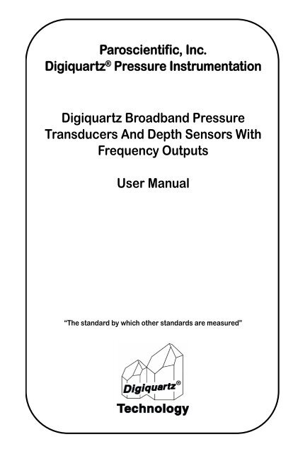
Digiquartz Broadband Pressure Transducers ... - Paroscientific, Inc.
Digiquartz Broadband Pressure Transducers ... - Paroscientific, Inc.
Digiquartz Broadband Pressure Transducers ... - Paroscientific, Inc.

You also want an ePaper? Increase the reach of your titles
YUMPU automatically turns print PDFs into web optimized ePapers that Google loves.
<strong>Paroscientific</strong>, <strong>Inc</strong>.<br />
<strong>Digiquartz</strong> ® <strong>Pressure</strong> Instrumentation<br />
<strong>Digiquartz</strong> <strong>Broadband</strong> <strong>Pressure</strong><br />
<strong>Transducers</strong> And Depth Sensors With<br />
Frequency Outputs<br />
User Manual<br />
“The standard by which other standards are measured”
<strong>Digiquartz</strong> ® <strong>Broadband</strong> <strong>Pressure</strong><br />
<strong>Transducers</strong> And Depth Sensors With<br />
Frequency Outputs<br />
User Manual<br />
DOCUMENT NO. G8203<br />
REVISION N<br />
JULY 2011<br />
WWW.PAROSCIENTIFIC.COM<br />
COPYRIGHT 2011 PAROSCIENTIFIC, INC.
Contents<br />
1. Introduction 7<br />
1.1 Conventions . . . . . . . . . . . . . . . . . . . . . . . . . . . . . . . . . . . . . 7<br />
2. Getting Familiar 9<br />
2.1 Features . . . . . . . . . . . . . . . . . . . . . . . . . . . . . . . . . . . . . . . . 9<br />
2.2 Physical Inspection . . . . . . . . . . . . . . . . . . . . . . . . . . . . . . . 9<br />
2.3 Handling Precautions . . . . . . . . . . . . . . . . . . . . . . . . . . . . . . 9<br />
2.4 Documents . . . . . . . . . . . . . . . . . . . . . . . . . . . . . . . . . . . . . 10<br />
3. Installation 11<br />
3.1 <strong>Pressure</strong> Ports and Buffer Tubes . . . . . . . . . . . . . . . . . . . . 11<br />
3.2 Oil Filled vs. Non-Oil Filled Units . . . . . . . . . . . . . . . . . . 12<br />
4. Electrical 13<br />
4.1 Characteristics . . . . . . . . . . . . . . . . . . . . . . . . . . . . . . . . . . 13<br />
5. Calculating <strong>Pressure</strong> and Temperature 15<br />
5.1 Temperature Calculation . . . . . . . . . . . . . . . . . . . . . . . . . . 15<br />
5.2 <strong>Pressure</strong> Calculation. . . . . . . . . . . . . . . . . . . . . . . . . . . . . . 15<br />
6. <strong>Digiquartz</strong> Data Storage (DDS) 17<br />
6.1 DDS Wires . . . . . . . . . . . . . . . . . . . . . . . . . . . . . . . . . . . . 17<br />
6.2 EEPROM Type . . . . . . . . . . . . . . . . . . . . . . . . . . . . . . . . . 17<br />
6.3 Chip Address . . . . . . . . . . . . . . . . . . . . . . . . . . . . . . . . . . . 17<br />
6.4 Memory Map . . . . . . . . . . . . . . . . . . . . . . . . . . . . . . . . . . . 18<br />
7. Accessories and Software 21<br />
7.1 Model 735 Intelligent Display . . . . . . . . . . . . . . . . . . . . . . 21<br />
7.2 <strong>Digiquartz</strong> Intelligent Interface Board . . . . . . . . . . . . . . . . 21<br />
7.3 Model 715 Display. . . . . . . . . . . . . . . . . . . . . . . . . . . . . . . 21<br />
7.4 <strong>Digiquartz</strong> Software Programs. . . . . . . . . . . . . . . . . . . . . . 22<br />
v<br />
•
8. Calibration 23<br />
9. Warranty and Technical Support 25<br />
9.1 Warranty Information . . . . . . . . . . . . . . . . . . . . . . . . . . . . 25<br />
9.2 Technical Support and Service . . . . . . . . . . . . . . . . . . . . . 26<br />
10. <strong>Pressure</strong> Unit Conversion Table 27<br />
vi<br />
•
•<br />
1 Introduction<br />
• •••••••••••••••••••••••••<br />
This manual is intended to offer installation and start up information for <strong>Paroscientific</strong><br />
<strong>Digiquartz</strong> ® <strong>Broadband</strong> <strong>Pressure</strong> <strong>Transducers</strong> and Depth Sensors with frequency outputs.<br />
<strong>Digiquartz</strong> <strong>Broadband</strong> <strong>Pressure</strong> <strong>Transducers</strong> are precision instruments and, as such, must<br />
be used with a certain degree of care. To ensure optimum performance, please follow the<br />
installation and handling recommendations presented in this manual.<br />
Additional product, installation, and operating information is available on the<br />
<strong>Paroscientific</strong> website at www.paroscientific.com.<br />
1.1 Conventions<br />
The following conventions are used throughout this manual:<br />
<strong>Digiquartz</strong> <strong>Broadband</strong> <strong>Pressure</strong> Transducer – Any <strong>Digiquartz</strong> <strong>Broadband</strong> <strong>Pressure</strong><br />
Transducer with frequency outputs.<br />
<strong>Digiquartz</strong> <strong>Broadband</strong> Depth Sensor – Any <strong>Digiquartz</strong> <strong>Broadband</strong> <strong>Pressure</strong> Transducer<br />
with frequency outputs that is specially packaged for depth sensing applications.<br />
CAUTION<br />
is used to draw your attention to a situation that may result in an undesirable outcome,<br />
but will not damage the unit.<br />
WARNING<br />
is used to draw your attention to a situation that may result in permanent damage to the<br />
unit or will void the warranty.<br />
DANGER<br />
is used to draw your attention to a situation that may result in injury.<br />
INTRODUCTION<br />
7<br />
•
- This page intentionally left blank -<br />
8<br />
INTRODUCTION<br />
•
•<br />
2 Getting Familiar<br />
2.1 Features<br />
• •••••••••••••••••••••••••<br />
General descriptions and feature summaries for <strong>Digiquartz</strong> <strong>Broadband</strong> <strong>Pressure</strong><br />
<strong>Transducers</strong> can be found on the <strong>Paroscientific</strong> website at www.paroscientific.com.<br />
Additional details are shown on the Specification Control Drawing that is shipped with the<br />
transducer.<br />
2.2 Physical Inspection<br />
You should have received the following items with your <strong>Digiquartz</strong> <strong>Broadband</strong> <strong>Pressure</strong><br />
Transducer purchase:<br />
• <strong>Digiquartz</strong> <strong>Broadband</strong> <strong>Pressure</strong> Transducer or Depth Sensor<br />
• User’s manual<br />
• Specification Control Drawing (SCD) for the <strong>Digiquartz</strong> <strong>Broadband</strong> <strong>Pressure</strong><br />
Transducer or Depth Sensor<br />
• Calibration Coefficient Sheet<br />
• Certificate of Calibration<br />
• Certificate of Conformance<br />
2.3 Handling Precautions<br />
<strong>Digiquartz</strong> <strong>Broadband</strong> <strong>Pressure</strong> <strong>Transducers</strong> are precision devices and, as such, they should<br />
be operated with a certain degree of care to ensure optimum performance.<br />
WARNING<br />
It is recommended that the input pressure not exceed the specified limit. Calibration can<br />
be affected if this limit is exceeded, and permanent damage can result if the unit is<br />
sufficiently overpressured.<br />
WARNING<br />
Excessive mechanical shock may cause irreparable damage. Do not drop a <strong>Digiquartz</strong><br />
<strong>Broadband</strong> <strong>Pressure</strong> Transducer, or allow tools or other hard objects to fall on the unit<br />
or its pressure port. If so equipped, the nylon or stainless steel buffer tube is an integral<br />
part of the transducer’s shock isolation system, and should not be removed.<br />
GETTING FAMILIAR<br />
9<br />
•
2.4 Documents<br />
The following documents are supplied with each <strong>Digiquartz</strong> <strong>Broadband</strong> <strong>Pressure</strong><br />
Transducer.<br />
SPECIFICATION CONTROL DRAWING (SCD)<br />
The SCD is a drawing that contains information about the performance, characteristics,<br />
environmental specifications, and physical dimensions of the unit.<br />
CALIBRATION COEFFICIENT SHEET<br />
The Calibration Coefficient Sheet contains the calibration coefficient values and the<br />
associated modeling equations (see Section 5). The calibration coefficients are derived<br />
from a calibration test run, and are unique to each <strong>Digiquartz</strong> <strong>Broadband</strong> <strong>Pressure</strong><br />
Transducer.<br />
CERTIFICATE OF CALIBRATION<br />
The Certificate of Calibration identifies the primary pressure standard(s) used to calibrate<br />
the <strong>Digiquartz</strong> <strong>Broadband</strong> <strong>Pressure</strong> Transducer.<br />
CERTIFICATE OF CONFORMANCE<br />
The Certificate of Conformance certifies that the <strong>Digiquartz</strong> <strong>Broadband</strong> <strong>Pressure</strong><br />
Transducer was manufactured in accordance with the applicable engineering drawings,<br />
process specifications, procedures, and specification control drawing. It also certifies that<br />
the <strong>Digiquartz</strong> <strong>Broadband</strong> <strong>Pressure</strong> Transducer was tested against NIST-traceable primary<br />
pressure standards, temperature standards, and pressure transfer standards that are regularly<br />
checked and calibrated per documented <strong>Paroscientific</strong> procedures in accordance with ISO<br />
9001 requirements.<br />
10<br />
GETTING FAMILIAR<br />
•
•<br />
3 Installation<br />
• •••••••••••••••••••••••••<br />
<strong>Digiquartz</strong> <strong>Broadband</strong> <strong>Pressure</strong> <strong>Transducers</strong> can generally be mounted in any orientation.<br />
Mounting hole patterns for units so equipped can be found on the Specification Control<br />
Drawing (SCD) supplied with the unit.<br />
CAUTION<br />
<strong>Pressure</strong> head effects vary with transducer orientation, and result in zero offsets. These<br />
effects are more pronounced when liquid-filled pressure lines are being used. These<br />
effects can be minimized by keeping the transducer pressure port and the pressure<br />
source at the same elevation, or by making an offset correction to compensate for the<br />
pressure head.<br />
3.1 <strong>Pressure</strong> Ports and Buffer Tubes<br />
<strong>Digiquartz</strong> <strong>Broadband</strong> <strong>Pressure</strong> <strong>Transducers</strong> typically include a nylon or stainless steel<br />
buffer tube. The buffer tube is an integral part of the mechanical shock protection system<br />
of the transducer.<br />
Parker A-Lok or equivalent nut and ferrule compression tube fittings are used on most<br />
<strong>Digiquartz</strong> <strong>Broadband</strong> <strong>Pressure</strong> <strong>Transducers</strong>. Series 2000 devices require 1/8” diameter<br />
tubing fittings for installation, while series 3000 and 4000 use 1/16” diameter tube fittings.<br />
Two 7/16" wrenches are required when making or breaking any 1/8-inch pressure fitting.<br />
The first wrench is used to stabilize the stationary fitting, and the second wrench is used to<br />
turn the other fitting.<br />
High-pressure transducers (Series 3000 and Series 4000) use the 1/16" Parker A-Lok or<br />
equivalent fittings. Two 5/16" wrenches are required to make and break these connections.<br />
CAUTION<br />
It is recommended that pressure fittings be installed finger tight, then tightened an<br />
additional ¾ turn to complete the pressure seal.<br />
WARNING<br />
Avoid making connections directly to the transducer pressure fitting. Make connections<br />
to the buffer tube fitting wherever possible. If the transducer pressure fitting becomes<br />
flared, stripped or damaged, it will be necessary to return the unit to <strong>Paroscientific</strong> for<br />
repairs.<br />
WARNING<br />
Do not remove the buffer tube. It is an integral part of the mechanical shock protection<br />
system of the transducer.<br />
INSTALLATION<br />
11<br />
•
3.2 Oil Filled vs. Non-Oil Filled Units<br />
OIL FILLED TRANSDUCERS<br />
<strong>Transducers</strong> that are to be used to measure liquid media pressures are oil filled at<br />
<strong>Paroscientific</strong>. <strong>Transducers</strong> that are oil filled should never be used in gas media<br />
applications.<br />
Oil fill and bleed all pressure lines that are to be connected to an oil filled transducer. The<br />
same oil used to fill the transducer should be used to fill the pressure lines; consult the<br />
transducer Specification Control Drawing for details.<br />
CAUTION<br />
If your transducer and buffer tube are oil filled, do not pull a vacuum or apply<br />
pressurized gas to the unit. Doing so could allow bubbles to form in the pressure lines<br />
and transducer, which will adversely affect the accuracy of the unit.<br />
CAUTION<br />
<strong>Pressure</strong> head effects result in zero offsets. These effects are more pronounced when<br />
liquid filled pressure lines are being used. These effects can be minimized by keeping<br />
the transducer pressure port and the pressure source at the same elevation, or by<br />
making an offset correction to compensate for the pressure head.<br />
NON-OIL FILLED TRANSDUCERS<br />
Non-oil filled transducers are intended for use in gas media applications, and should never<br />
be used in liquid media applications.<br />
WARNING<br />
If your transducer and buffer tube are not oil-filled, do not apply pressurized liquid media<br />
to the unit. Liquid may contaminate the unit, and may adversely affect the accuracy of<br />
the unit. It is not possible to completely remove most liquids from the transducer once<br />
they have been introduced.<br />
12<br />
INSTALLATION<br />
•
•<br />
4 Electrical<br />
4.1 Characteristics<br />
• •••••••••••••••••••••••••<br />
PRESSURE SIGNAL<br />
Signal Type:<br />
Amplitude:<br />
Source Impedance:<br />
Range:<br />
TEMPERATURE SIGNAL<br />
Signal Type:<br />
Amplitude:<br />
Source Impedance:<br />
Range:<br />
AC coupled nominal square wave<br />
Nominal 4V peak to peak<br />
Less than 750 Ohms<br />
Nominal 10% frequency change within the band of<br />
30 kHz to 42 kHz.<br />
AC coupled nominal square wave<br />
Nominal 4V peak to peak<br />
Less than 750 Ohms<br />
Nominal 45 ppm/C sensitivity within the band of<br />
168 kHz to 174 kHz.<br />
SUPPLY VOLTAGE<br />
Refer to Specification Control Drawing supplied with transducer.<br />
CURRENT CONSUMPTION<br />
Refer to Specification Control Drawing supplied with transducer.<br />
WARNING<br />
Power/signal ground are connected to the transducer pressure fitting (and in some<br />
cases, the transducer housing) through a 0.1µF 50V capacitor. To prevent damage to<br />
the transducer electronics, ensure that the potential between power/signal ground and<br />
the pressure fitting does not exceed 50V.<br />
CAUTION<br />
Current consumption increases when driving long lines or low impedances. Refer to the<br />
Specification Control Drawing supplied with the transducer for output loading<br />
recommendations.<br />
ELECTRICAL<br />
13<br />
•
TRANSDUCER WIRES<br />
Most <strong>Digiquartz</strong> <strong>Broadband</strong> <strong>Pressure</strong> <strong>Transducers</strong> bring out their output and power<br />
connections on flying wire leads. The pressure and temperature signals are typically<br />
brought out separately as twisted pairs with power/signal ground. The wires are colorcoded<br />
per following table:<br />
TABLE 4-1: Transducer Wire Color-Coding<br />
Wire Color<br />
Signal<br />
Red<br />
Power<br />
Blue / Black twisted <strong>Pressure</strong> Signal / Ground<br />
White / Black twisted Temperature Signal / Ground<br />
CAUTION<br />
Do not bundle pressure and temperature wires together. Doing so can cause the<br />
temperature signal to couple into the pressure signal, which may result in an<br />
unnecessarily noisy pressure signal.<br />
CAUTION<br />
If pressure and temperature wires are to be extended, also extend the associated black<br />
ground wires, and ensure that the extension wires are also twisted at a rate of at least<br />
4 to 5 twists per inch. Failure to do so can cause the temperature signal to couple into<br />
the pressure signal, which may degrade sensor performance.<br />
14<br />
ELECTRICAL<br />
•
•<br />
5 Calculating <strong>Pressure</strong> and Temperature<br />
• •••••••••••••••••••••••••<br />
Internal sensor temperature and applied pressure are calculated from period measurements<br />
of the two transducer output signals. The equations and coefficients used to perform these<br />
calculations are described below. Refer to the Calibration Coefficient Sheet for the actual<br />
coefficient values for your transducer.<br />
5.1 Temperature Calculation<br />
The following equation is used to calculate internal sensor temperature:<br />
T = Y 1 U + Y 2 U 2 + Y 3 U 3<br />
Where:<br />
T = Temperature (°C)<br />
U 0 = temperature signal period (microseconds) at 25° C<br />
U = temperature signal period (microseconds) – U 0 (microseconds)<br />
Temperature coefficients: U 0 Y 1 Y 2 Y 3<br />
5.2 <strong>Pressure</strong> Calculation<br />
The following equation is used to calculate pressure:<br />
P = C(1 – T 0 2 /Tau 2 )[1 – D(1– T 0 2 /Tau 2 )]<br />
Where:<br />
P = pressure<br />
Tau = pressure signal period (microseconds)<br />
U = temperature signal period (microseconds) – U 0 (microseconds)<br />
C = C 1 + C 2 U + C 3 U 2<br />
D = D 1 + D 2 U<br />
T 0 = T 1 + T 2 U + T 3 U 2 + T 4 U 3 + T 5 U 4<br />
<strong>Pressure</strong> coefficients: C 1 C 2 C 3 D 1 D 2 T 1 T 2 T 3 T 4 T 5<br />
CALCULATING PRESSURE AND TEMPERATURE<br />
15<br />
•
- This page intentionally left blank -<br />
16<br />
CALCULATING PRESSURE AND TEMPERATURE<br />
•
•<br />
6 <strong>Digiquartz</strong> Data Storage (DDS)<br />
• •••••••••••••••••••••••••<br />
Most <strong>Digiquartz</strong> <strong>Broadband</strong> <strong>Pressure</strong> <strong>Transducers</strong> include the <strong>Digiquartz</strong> Data Storage<br />
(DDS) feature. <strong>Transducers</strong> with DDS can be identified by the presence of the wires<br />
described in Section 6.1.<br />
<strong>Digiquartz</strong> Data Storage (DDS) is an onboard serial EEPROM that contains calibration and<br />
transducer information. This information can be accessed electronically to provide plug and<br />
play pressure transducer interchangeability. An additional 4k bytes of DDS EEPROM<br />
memory has been allocated for customer use.<br />
NOTE: The sole purpose of DDS is to store transducer configuration information.<br />
Use of DDS is optional, and does not affect pressure measurement. A minimum wire<br />
length of 6 inches is required to program DDS. If one chooses to remove the DDS wires,<br />
the recommended method is to cut the DDS wires to the desired length and protect the<br />
exposed leads with heat shrink.<br />
WARNING<br />
Voltages outside the range of -0.3 to 4.3 volts must not be applied to the SDA (Serial<br />
Data) and SCL (Serial Clock) signal lines. Doing so will damage the DDS serial<br />
EEPROM.<br />
CAUTION<br />
The maximum recommended length of the SDA and SCL wires is 18 inches. Serial<br />
communication with the serial EEPROM may become unreliable at longer wire lengths.<br />
6.1 DDS Wires<br />
TABLE 6-1: DDS Wire Color-Coding<br />
Wire Color<br />
Signal<br />
White / Brown<br />
SCL<br />
White / Violet<br />
SDA<br />
Black<br />
Ground<br />
6.2 EEPROM Type<br />
The DDS serial EEPROM is a Microchip Technology 24LC64 or equivalent. For interface<br />
information, please consult the manufacturer’s data sheet for this device, which can be<br />
obtained at the Microchip Technology website at www.microchip.com.<br />
6.3 Chip Address<br />
The chip address of the DDS serial EEPROM is fixed at binary 101. Any device used to<br />
communicate with DDS must be able to select the proper chip address.<br />
DIGIQUARTZ DATA STORAGE (DDS)<br />
17<br />
•
6.4 Memory Map<br />
The information stored in DDS memory is organized as shown in the table below. All data<br />
are stored in fixed length fields in ASCII format. All used fields are padded from the end<br />
of the data to the end of the field with space characters (ASCII 32 decimal).<br />
256 bytes of data storage starting at address 1000 hex has been reserved for your use.<br />
CAUTION<br />
Do not store data at addresses below 1000 hex. This memory space is reserved for<br />
<strong>Paroscientific</strong> use.<br />
Table 6-2: DDS Memory Map<br />
Field No Address Description Field Length<br />
(Hex)<br />
(Bytes)<br />
General Information<br />
1 0000-000F EEPROM Revision 16<br />
2 - 6 0010-005F Customer Information 80<br />
7 - 11 0060-00AF Reserved 80<br />
Sensor Information<br />
12 00B0-00BF Serial Number 16<br />
13 00C0-00CF Part Number 16<br />
14-15 00D0-00EF Model Description 32<br />
16-17 00F0-010F <strong>Pressure</strong> Range 32<br />
18-19 0110-012F Temperature Range 32<br />
20 0130-013F Report Date 16<br />
21 0140-014F <strong>Pressure</strong> Medium 16<br />
22 0150-015F Sensor Type 16<br />
23 - 27 0160-01AF Reserved 80<br />
Calibration Data<br />
28 01B0-01BF Calibration Date 16<br />
29 01C0-01CF <strong>Pressure</strong> Units 16<br />
30 01D0-01DF Temperature Units 16<br />
31 01E0-01EF U0 Coefficient 16<br />
32 01F0-01FF Y1 Coefficient 16<br />
33 0200-020F Y2 Coefficient 16<br />
34 0210-021F Y3 Coefficient 16<br />
35 0220-022F C1 Coefficient 16<br />
36 0230-023F C2 Coefficient 16<br />
37 0240-024F C3 Coefficient 16<br />
38 0250-025F D1 Coefficient 16<br />
39 0260-026F D2 Coefficient 16<br />
40 0270-027F T1 Coefficient 16<br />
41 0280-028F T2 Coefficient 16<br />
18<br />
DIGIQUARTZ DATA STORAGE (DDS)<br />
•
Table 6-2: DDS Memory Map<br />
Field No Address Description Field Length<br />
(Hex)<br />
(Bytes)<br />
Calibration Data<br />
42 0290-029F T3 Coefficient 16<br />
43 02A0-02AF T4 Coefficient 16<br />
44 02B0-02BF T5 Coefficient 16<br />
45 02C0-02CF <strong>Pressure</strong> Adder 16<br />
46 02D0-02DF <strong>Pressure</strong> Multiplier 16<br />
47 - 51 02E0-032F Reserved 80<br />
Common-Mode Calibration<br />
52 0330-033F Common-Mode<br />
10<br />
Coefficient Units<br />
53 0340-034F A1 Coefficient 16<br />
54 0350-035F A2 Coefficient 16<br />
55 0360-036F B1 Coefficient 16<br />
56 0370-037F P0 Coefficient 16<br />
Reserved<br />
57 - 256 0380-05CF <strong>Paroscientific</strong> Reserved 592<br />
257 - 512 1000-1FFF User Reserved 4096<br />
DIGIQUARTZ DATA STORAGE (DDS)<br />
19<br />
•
- This page intentionally left blank -<br />
20<br />
DIGIQUARTZ DATA STORAGE (DDS)<br />
•
•<br />
7 Accessories and Software<br />
• •••••••••••••••••••••••••<br />
7.1 Model 735 Intelligent Display<br />
If your application requires RS-232 interface, a display, or transducer control and<br />
monitoring without a computer, the Model 735 can be the best choice for you. The Model<br />
735 Intelligent Display performs all of the functions of the Model 745 High Accuracy<br />
Portable Standard when connected to a single external <strong>Digiquartz</strong> Transducer. It features an<br />
intuitive front panel menu system, two-line display, RS-232 communication port, tare<br />
capability, and transducer connection terminals.<br />
The Model 735 can be powered from its AC adapter, or for up to 20 hours from AA alkaline<br />
batteries. Configuration and data logging software provided with the unit allows the user to<br />
configure and log data from Model 735 via RS-232.<br />
7.2 <strong>Digiquartz</strong> Intelligent Interface Board<br />
The <strong>Digiquartz</strong> Intelligent Interface Board is a microprocessor-based interface that<br />
processes the frequency outputs from a single <strong>Digiquartz</strong> transducer. It provides fully<br />
temperature-compensated pressure measurement values in the user’s choice of engineering<br />
units. Dual RS-232 and RS-485 serial interfaces are provided. The user may program the<br />
sample rate, integration time, engineering units, and communication parameters via the<br />
serial interfaces. Multiple transducer/board combinations can be connected together to<br />
form an RS-232 serial loop or RS-485 multi-drop network.<br />
Set-up and data acquisition software are included with the <strong>Digiquartz</strong> Intelligent Interface<br />
Board.<br />
The <strong>Digiquartz</strong> Intelligent Interface Board is compatible with the Model 715 display.<br />
7.3 Model 715 Display<br />
The Model 715 displays pressure and temperature data from all <strong>Paroscientific</strong> Intelligent<br />
Transmitters that have dual RS-232 and RS-485 interfaces. The two-line, 16-character<br />
backlit alphanumeric liquid crystal display is set up with transmitter commands and<br />
included software. Display functions include pressure and temperature values with<br />
engineering units, overpressure warning, tare indicator, user defined text messages, and a<br />
horizontal analog bar graph showing pressure as a percentage of full-scale pressure.<br />
The Model 715 will respond to display commands from a <strong>Digiquartz</strong> transmitter, a<br />
computer, or other serial host on either the RS-232 or RS-485 port. For stand-alone<br />
operation, it can display data whenever power is applied to the transmitter.<br />
ACCESSORIES AND SOFTWARE<br />
21<br />
•
7.4 <strong>Digiquartz</strong> Software Programs<br />
<strong>Paroscientific</strong> provides software programs that simplify common measurement and<br />
configuration tasks. The latest versions of these and other software programs are available<br />
at the <strong>Paroscientific</strong> web site www.paroscientific.com.<br />
<strong>Digiquartz</strong> <strong>Broadband</strong> <strong>Pressure</strong> <strong>Transducers</strong> require an intelligent board or Model 735<br />
Intelligent Display to interface with PC-based <strong>Digiquartz</strong> Software.<br />
A transducer can also interface directly with third-party data acquisition systems that<br />
measure frequency signals. In this case, the user would need to develop their own software<br />
to acquire and process the signal output from the transducer.<br />
7.4.1 <strong>Digiquartz</strong> Interactive 2.0 (DQI 2.0)<br />
<strong>Digiquartz</strong> Interactive 2.0 is a Windows program that makes it easy to communicate with<br />
and configure DIGIQUARTZ Intelligent devices. We encourage you to install DQI 2.0 and<br />
use it to verify proper device operation, configure your device, take measurements, and<br />
experiment with its functions.<br />
DQI 2.0 is separated into two main sections: Configuration and Monitoring, and <strong>Digiquartz</strong><br />
Terminal.<br />
The Configuration and Monitoring section provides a means of viewing, changing, storing,<br />
and retrieving the configuration parameters of your instrument. It also allows you to take<br />
measurements and display them numerically and in a real-time graph. Measurement data<br />
may also be logged to a text file in a format that can be easily imported into popular PC<br />
programs such as Microsoft Excel® or Word®.<br />
The <strong>Digiquartz</strong> Terminal section allows you to interactively communicate with your<br />
instrument using text-based commands. Measurement data may be logged to a text file in<br />
a format that can be easily imported into popular PC programs such as Microsoft Excel or<br />
Word.<br />
7.4.2 <strong>Digiquartz</strong> Assistant (DQA)<br />
DIGIQUARTZ Assistant is a Windows data logging program. With DQA, you can log<br />
time-stamped measurement data from up to 8 DIGIQUARTZ Intelligent devices.<br />
Measurement data can also be displayed in real time in an automatically scaled graph. Data<br />
is stored to a text file in a format that can easily be imported into popular PC programs such<br />
as Microsoft Word or Excel. Refer to the help function in DQA for more information.<br />
22<br />
ACCESSORIES AND SOFTWARE<br />
•
•<br />
8 Calibration<br />
• •••••••••••••••••••••••••<br />
<strong>Paroscientific</strong> is the leader in the high precision pressure measurement field where high<br />
resolution, accuracy, reliability, ruggedness, long-term stability, and low cost of ownership<br />
are important requirements. The high performance of <strong>Digiquartz</strong> Instruments is a result of<br />
careful design, meticulous manufacturing, and extensive calibration and testing. The<br />
construction, operation, and performance of <strong>Paroscientific</strong> transducers are described on our<br />
web site.<br />
Calibration is performed by applying known pressures from primary standards to manifolds<br />
of transducers mounted in temperature chambers. Two frequency (or period) output signals<br />
are sent from each transducer. <strong>Pressure</strong> is measured with a force-sensitive quartz crystal<br />
whose output period changes with applied load. A second period output comes from a<br />
quartz crystal temperature sensor used for thermal compensation. The manifold of<br />
transducer signals are multiplexed, measured, and the data fit to derive coefficients for the<br />
standard equation that characterizes the transducers. The calibration coefficients provided<br />
with each transducer and the indicated pressure (calculated) will agree with the "true"<br />
applied pressure with a typical accuracy of 0.01 percent or better of transducer full scale<br />
over the full operational range of pressures and temperatures. <strong>Digiquartz</strong> Intelligent<br />
Transmitters store the calibration coefficients in non-volatile EEPROM to provide fully<br />
temperature-compensated and linearized outputs on the bi-directional RS-232 and RS-485<br />
interfaces.<br />
Because the recalibration period of <strong>Digiquartz</strong> Instruments depends on specific<br />
applications and user requirements, we do not recommend a typical interval between<br />
calibrations. Some customers never recalibrate their instruments, while others recalibrate<br />
periodically every 1 to 3 years. A test report on long-term stability of <strong>Digiquartz</strong><br />
Barometers can be found on our web site.<br />
Equally amazing stability has been shown with high-pressure depth sensors in<br />
oceanographic deployments. After 30 years and 100,000 transducers, we have not detected<br />
a change in span (scale factor) with time. Therefore, the only correction made to<br />
instruments during recalibration is usually a small offset adjustment. With no pressure<br />
applied to gauge or differential transducers, the adjustment equals the indicated value. For<br />
absolute instruments, an effective adjustment (especially on higher pressure ranges) can<br />
simply be the difference between the indicated value and a single "true" pressure. The<br />
calibration adjustments may be done via the PA (<strong>Pressure</strong> Adder) and PM (<strong>Pressure</strong><br />
Multiplier) parameters on the Intelligent Instruments or via the C1 and T1 calibration<br />
coefficients for frequency output transducers.<br />
<strong>Paroscientific</strong>’s Quality Assurance System is certified to the requirements of the ISO 9001<br />
International Quality Standard and provides consistency in our products and processes<br />
from design and development through production, calibration, test, and servicing. Our<br />
calibration system meets MIL-STD 45662A and is traceable to NIST.<br />
CALIBRATION<br />
23<br />
•
<strong>Digiquartz</strong> absolute transducers, transmitters, and portable standards, with full scale<br />
pressure ranges of 500 psia or less, come with a certificate for one FREE inspection,<br />
calibration check, zero adjustment, and new Certificate of NIST Traceability within the<br />
first two years of shipment.<br />
24<br />
CALIBRATION<br />
•
•<br />
9 Warranty and Technical Support<br />
• •••••••••••••••••••••••••<br />
9.1 Warranty Information<br />
DIGIQUARTZ TRANSDUCERS<br />
5-YEAR EXTENDED LIMITED WARRANTY<br />
<strong>Paroscientific</strong> highly values our customers. A Quality Management System that is certified<br />
to the requirements of the ISO 9001 International Quality Standard provides consistency in<br />
our products and processes from design and development through production, calibration,<br />
test, and servicing. Our quality system and commitment to excellence ensure customers<br />
of outstanding products and services. As a result, we offer a one-year warranty on all<br />
instrumentation systems, and a full five-year limited warranty on all <strong>Digiquartz</strong> transducers<br />
that is unmatched in the industry.<br />
This policy applies to all <strong>Digiquartz</strong> transducers manufactured by <strong>Paroscientific</strong>, and<br />
includes the repair and/or replacement of parts that are required to maintain the unit to the<br />
“as purchased” configuration. Excluded from this policy are the following: conversions,<br />
product modification, zero adjustments, recalibration, and service analysis charges. This<br />
“Extended Limited Warranty” is a supplement to <strong>Paroscientific</strong>, <strong>Inc</strong>.’s “Terms and<br />
Conditions of Sale”. Shipping charges are the responsibility of the customer.<br />
Months From Shipment Discount From List Price<br />
0 - 24 100%<br />
25 - 36 75%<br />
37 - 48 50%<br />
49 - 60 25%<br />
CONDITIONS:<br />
• The warranty period is from the date of shipment from <strong>Paroscientific</strong> to date of<br />
receipt at <strong>Paroscientific</strong>.<br />
• The customer must authorize the repair or replacement of the warranty claim<br />
within 45 days of notification by our Service Department.<br />
• No exceptions to the discount schedule or terms of this policy are allowed.<br />
• This warranty does not apply to units broken due to overpressure or excessive<br />
shock.<br />
• Warranty returned units become the property of <strong>Paroscientific</strong> upon<br />
replacement.<br />
All barometers also have a three year limited warranty on long-term stability. Years 4<br />
and 5 are covered by the above schedule.<br />
WARRANTY AND TECHNICAL SUPPORT<br />
25<br />
•
9.2 Technical Support and Service<br />
Support is available via the <strong>Paroscientific</strong> website at www.paroscientific.com. Technical<br />
information, application notes, software and product manuals are also available on our<br />
website. Please check the Troubleshooting section of this manual if you are having<br />
problems with your instrument. If you need assistance, contact our sales and application<br />
engineers at support@paroscientific.com or (425) 883-8700.<br />
For information on returning an instrument to us for disposal (Waste Electrical and<br />
Electronic Equipment - WEEE), please see the Disposal section of our web site for<br />
documentation requirements and packaging instructions.<br />
If you are sending an instrument to us for service, please check our web site under the<br />
service section for detailed instructions for shipping a unit to us for service.<br />
26<br />
WARRANTY AND TECHNICAL SUPPORT<br />
•
•<br />
10 <strong>Pressure</strong> Unit Conversion Table<br />
• •••••••••••••••••••••••••<br />
To use this table:<br />
• Determine original pressure unit and desired pressure unit.<br />
• Using the table, identify the appropriate pressure conversion factor.<br />
• Multiply the original pressure value by the conversion factor to convert it to the desired pressure unit.<br />
Original<br />
<strong>Pressure</strong><br />
Unit<br />
TABLE 10-1: <strong>Pressure</strong> Unit Conversion Table<br />
Desired <strong>Pressure</strong> Unit<br />
Meters H2O Pounds/in 2 <strong>Inc</strong>hes of mercury Millimeters of<br />
mercury or Torr<br />
Gram/cm 2<br />
Millibar or<br />
Hectopascal<br />
Pascal or<br />
Newton/m 2<br />
g/cm 3 psi in Hg mm Hg or Torr g/cm 2 mbar or hPa Pa or N/m 2<br />
g/cm 3 1 1.422334 2.895903 73.5592 100.0000 98.06650 9806.650<br />
psi .7030696 1 2.036021 51.71493 70.30696 68.94757 6894.757<br />
in Hg .3453155 .4911541 1 25.40000 34.53155 33.86388 3386.388<br />
mm Hg or Torr .01359510 .01933678 .03937008 1 1.359510 1.333224 133.3224<br />
g/cm 2 .01000000 .01422334 .02895903 .7355592 1 .9806650 98.06650<br />
mbar or hPa .01019716 .01450377 .02952999 .75000617 1.019716 1 100.0000<br />
Pa or N/m 2 1.019716x10⁻⁴ 1.450377x10⁻⁴ 2.952999x10⁻⁴ 7.500617x10⁻³ .01019716 .01000000 1<br />
PRESSURE UNIT CONVERSION TABLE<br />
27<br />
•
- This page intentionally left blank -<br />
28<br />
PRESSURE UNIT CONVERSION TABLE<br />
•
<strong>Paroscientific</strong>, <strong>Inc</strong>.<br />
4500 148th Avenue N.E.<br />
Redmond, WA 98052 USA<br />
Tel: (425) 883-8700<br />
Fax: (425) 867-5407<br />
Web: www.paroscientific.com<br />
E-mail: support@paroscientific.com<br />
Document No.: G8203<br />
Rev: N<br />
Date: July 2011<br />
© <strong>Paroscientific</strong>, <strong>Inc</strong>.