Transient Voltage Surge Suppression
Transient Voltage Surge Suppression
Transient Voltage Surge Suppression

You also want an ePaper? Increase the reach of your titles
YUMPU automatically turns print PDFs into web optimized ePapers that Google loves.
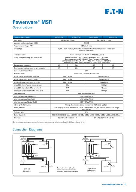
Powerware ® MSFi<br />
Specifications<br />
Technical Specifications MSF401CCMi <br />
Input voltage 220 – 254VAC 1 Phase <br />
Maximum continuous voltage - MCOV<br />
<br />
Temporary overvoltage - TOV<br />
<br />
Service type<br />
TT, TN, TN C-S or any system with a grounded neutral. This unit must not be connected to<br />
an ungrounded system<br />
Test Classification<br />
Energy Absorption rating - per mode (joules)<br />
<br />
<br />
Secondary protection L-N = 600J/ph, Three Phase unit = 1,800J total<br />
Common mode protection L-N & N-E = 1,420J, Three Phase unit = 4,280J total<br />
<br />
Current rating - continuous 40A 40A <br />
Recommended maximum over current protection 40A 40A <br />
Short circuit withstand (1 sec)<br />
<br />
Protection modes<br />
Line-Neutral, Line-Earth, Neutral-Earth<br />
In 8/20us (Line-Neutral) Nom. surge life 60kA x 20 hits 60kA x 20 hits/ph<br />
In 8/20us (Line-Earth) Nom. surge life 15kA x 20 hits 15kA x 20 hits/ph<br />
In 8/20us (Neutral-Earth) Nom. surge life 15kA x 20 hits 45kA x 20 hits<br />
Ismax 8/20us (Line-Neutral) Max surge level 160kA 160kA/ph<br />
Ismax 8/20us (Line-Earth) Max surge level 40kA 40kA/ph<br />
Ismax 8/20us (Neutral-Earth) Max surge level 40kA 120kA/ph<br />
Filter attenuation<br />
40dB nominal above 1MHz<br />
Initial clamp voltage (Line-Neutral)<br />
<br />
Initial clamp voltage (Line-Earth)<br />
680V (420Vac RMS)<br />
Initial clamp voltage (Neutral-Earth)<br />
680V (420Vac RMS)<br />
Internal protection (fusing)<br />
<br />
Alarms/indicators<br />
<br />
cutoff 180Vac.<br />
Enclosure rating<br />
IP24<br />
Design Standards:<br />
<br />
Dimensions 210 x 160 x 560 mm (W x D x H) <br />
Due to continual product improvement specifications are subject to change without notice. Copyright 2008 Eaton Industries Pty Ltd<br />
Connection Diagrams<br />
Min distance<br />
to ceiling 300mm<br />
Min distance<br />
to ceiling 300mm<br />
N L1 L2 L3<br />
OUTPUT<br />
LOAD<br />
N<br />
L<br />
OUTPUT<br />
LOAD<br />
Earth<br />
Earth<br />
N L1 L2 L3<br />
INPUT<br />
N<br />
L<br />
INPUT<br />
E<br />
Earth Stud<br />
On Case<br />
8mm<br />
E<br />
Earth Stud<br />
On Case<br />
8mm<br />
Min distance<br />
to floor 600mm<br />
Min distance<br />
to floor 600mm<br />
<br />
Connection<br />
MAIN S WB<br />
MAIN<br />
EARTHING<br />
POINT (SWB)<br />
Important: Before installing the<br />
device, please read and follow the<br />
installation and operating instructions.<br />
Single Phase<br />
Connection<br />
MAIN S WB<br />
MAIN<br />
EARTHING<br />
POINT (SWB)<br />
www.eatonelectric.com.au<br />
23