Investigations on Three Phase Five Level Flying Capacitor Multilevel ...
Investigations on Three Phase Five Level Flying Capacitor Multilevel ...
Investigations on Three Phase Five Level Flying Capacitor Multilevel ...

You also want an ePaper? Increase the reach of your titles
YUMPU automatically turns print PDFs into web optimized ePapers that Google loves.
Internati<strong>on</strong>al Journal of Engineering and Technology (IJET) – Volume 2 No. 7, July, 2012<br />
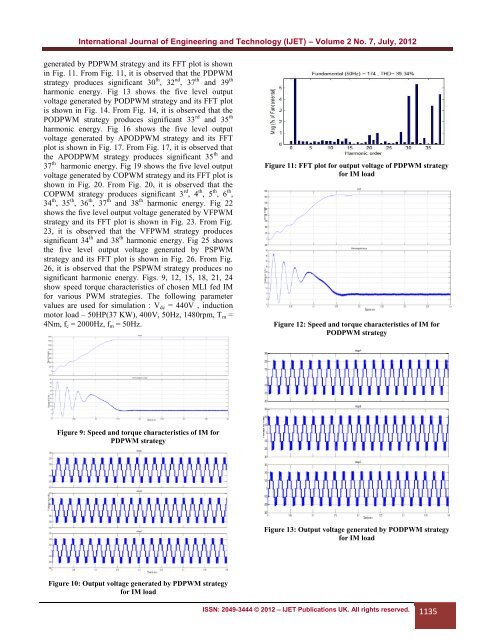
generated by PDPWM strategy and its FFT plot is shown<br />
in Fig. 11. From Fig. 11, it is observed that the PDPWM<br />
strategy produces significant 30 th , 32 nd , 37 th and 39 th<br />
harm<strong>on</strong>ic energy. Fig 13 shows the five level output<br />
voltage generated by PODPWM strategy and its FFT plot<br />
is shown in Fig. 14. From Fig. 14, it is observed that the<br />
PODPWM strategy produces significant 33 rd and 35 th<br />
harm<strong>on</strong>ic energy. Fig 16 shows the five level output<br />
voltage generated by APODPWM strategy and its FFT<br />
plot is shown in Fig. 17. From Fig. 17, it is observed that<br />
the APODPWM strategy produces significant 35 th and<br />
37 th harm<strong>on</strong>ic energy. Fig 19 shows the five level output<br />
voltage generated by COPWM strategy and its FFT plot is<br />
shown in Fig. 20. From Fig. 20, it is observed that the<br />
COPWM strategy produces significant 3 rd , 4 th , 5 th , 6 th ,<br />
34 th , 35 th , 36 th , 37 th and 38 th harm<strong>on</strong>ic energy. Fig 22<br />
shows the five level output voltage generated by VFPWM<br />
strategy and its FFT plot is shown in Fig. 23. From Fig.<br />
23, it is observed that the VFPWM strategy produces<br />
significant 34 th and 38 th harm<strong>on</strong>ic energy. Fig 25 shows<br />
the five level output voltage generated by PSPWM<br />
strategy and its FFT plot is shown in Fig. 26. From Fig.<br />
26, it is observed that the PSPWM strategy produces no<br />
significant harm<strong>on</strong>ic energy. Figs. 9, 12, 15, 18, 21, 24<br />
show speed torque characteristics of chosen MLI fed IM<br />
for various PWM strategies. The following parameter<br />
values are used for simulati<strong>on</strong> : V dc = 440V , inducti<strong>on</strong><br />
motor load – 50HP(37 KW), 400V, 50Hz, 1480rpm, T m =<br />
4Nm, f c = 2000Hz, f m = 50Hz.<br />
Figure 11: FFT plot for output voltage of PDPWM strategy<br />
for IM load<br />
Figure 12: Speed and torque characteristics of IM for<br />
PODPWM strategy<br />
Figure 9: Speed and torque characteristics of IM for<br />
PDPWM strategy<br />
Figure 13: Output voltage generated by PODPWM strategy<br />
for IM load<br />
Figure 10: Output voltage generated by PDPWM strategy<br />
for IM load<br />
ISSN: 2049-3444 © 2012 – IJET Publicati<strong>on</strong>s UK. All rights reserved. 1135