198934 Roof Stairs INSTALLATION INSTRUCTIONS.pdf - Westeel
198934 Roof Stairs INSTALLATION INSTRUCTIONS.pdf - Westeel
198934 Roof Stairs INSTALLATION INSTRUCTIONS.pdf - Westeel

You also want an ePaper? Increase the reach of your titles
YUMPU automatically turns print PDFs into web optimized ePapers that Google loves.
Part Number: <strong>198934</strong><br />
Revision: 8<br />
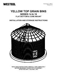
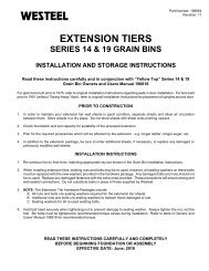
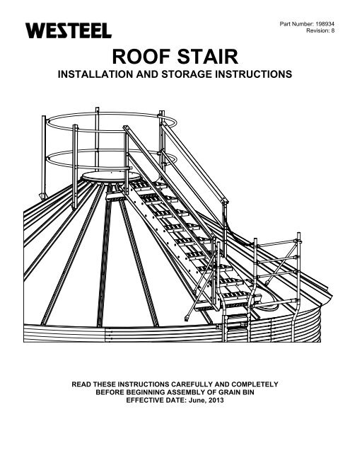
ROOF STAIR<br />
<strong>INSTALLATION</strong> AND STORAGE <strong>INSTRUCTIONS</strong><br />
READ THESE <strong>INSTRUCTIONS</strong> CAREFULLY AND COMPLETELY<br />
BEFORE BEGINNING ASSEMBLY OF GRAIN BIN<br />
EFFECTIVE DATE: June, 2013
TABLE OF CONTENTS<br />
Description<br />
Page<br />
Table of Contents ........................................................................ 2<br />
New in This Manual ..................................................................... 3<br />
Limited Warrenty ......................................................................... 4 & 5<br />
Disclaimers .................................................................................. 6<br />
Critical Assy ................................................................................. 7<br />
Product Storage ........................................................................... 8 & 9<br />
Important Notes ........................................................................... 10<br />
Planning the Location of Ladder Components ............................ 11<br />
<strong>Roof</strong> Stair Assembly .................................................................... 12<br />
External Ladder Assembly Considerations ........................... 13<br />
Typical <strong>Roof</strong> Stair Modules Layout ....................................... 14<br />
<strong>Roof</strong> Stair Module Layout ..................................................... 15<br />
Stair Assembly ...................................................................... 16 - 20<br />
Inspection Hatch Cage Assembly ......................................... 21 - 23<br />
<strong>Roof</strong> Stair Hardware Usage .................................................. 23<br />
<strong>Roof</strong> Stair Package Bills of Material ..................................... 24<br />
Optional Peak Rail Assembly ...................................................... 24 - 27<br />
Peak Rail Hardware Usage .................................................. 28<br />
Peak Rail Bills of Material .................................................... 28<br />
Optional Peak Platform Assembly .............................................. 29 - 31<br />
Peak Platform Hardware Usage .......................................... 31<br />
Peak Platform Bills of Material ............................................. 31<br />
Optional Stair Block-off Assembly .............................................. 32 - 34<br />
Stair Block-off Hardware Usage .......................................... 34<br />
Stair Block-off Bills of Material ............................................. 34<br />
Optional Catwalk Access Information ......................................... 35<br />
Appendix I - <strong>Roof</strong> Stair Part Identification ................................... 36 - 37<br />
Appendix II - <strong>Roof</strong> Stair Part Identification .................................. 38 - 39<br />
Page 2
NEW IN THIS MANUAL<br />
• Changed 234116 description from 30' to 54' Bins - to - 30' to 108' Bins, Page 31<br />
Page 3
LIMITED WARRANTY<br />
<strong>Westeel</strong> Division of Vicwest Operating Limited Partnership ("<strong>Westeel</strong>") warrants products that it<br />
has manufactured and/or that are branded with its name (the "goods") subject to the following<br />
terms and limitations, (the "warranty"):<br />
1. Duration of Warranty. The duration of the warranty is limited as follows:<br />
Galvanized Bins<br />
EasyCheck<br />
EasyFlow<br />
EasyAer<br />
Floors<br />
SeedStor-K Cones<br />
Paint<br />
Structural<br />
SeedStor Cones<br />
Paint<br />
Structural<br />
Elite Cones<br />
Paint<br />
Structural<br />
WESTEEL cones<br />
Paint<br />
Structural<br />
Smooth Wall Bins<br />
Paint<br />
Structural<br />
12 months<br />
12 months<br />
24 months<br />
12 months<br />
12 months<br />
12 months<br />
30 months<br />
30 months<br />
10 years<br />
30 months<br />
10 years<br />
no warranty<br />
12 months<br />
30 months<br />
10 years<br />
The duration of the warranty will run from the date of purchase from a dealer or distributor<br />
authorized by <strong>Westeel</strong> (the "warranty period").<br />
2. Limitation of Remedies Replacement. Within the warranty period, <strong>Westeel</strong> will replace<br />
the goods and/or original manufactured components thereof which are found, to <strong>Westeel</strong>'s<br />
satisfaction, to be defective. <strong>Westeel</strong> is not responsible for direct, indirect, special,<br />
consequential, or any other damages of any kind, including personal injury to any<br />
individual, howsoever caused, including caused by transportation of the goods for repair<br />
or replacement<br />
3. Procedure for Obtaining Service. In the event of a warranty claim, the purchaser must<br />
complete any and all information required by <strong>Westeel</strong> in order to properly assess or<br />
investigate the claim. <strong>Westeel</strong> will not be responsible for the removal of any of the goods<br />
found to be defective, or transportation charges to and from <strong>Westeel</strong>'s authorized dealer<br />
or distributor, or for installation of any replacement goods and/or parts furnished under the<br />
warranty.
Limitations as to Scope of Warranty. The warranty does not extend to defects or damage<br />
Page 4<br />
caused, in whole or in part, by:<br />
i. use of a kind and/or to a degree not reasonably expected to be made of the goods;<br />
ii.<br />
iii.<br />
iv.<br />
improper storage of the goods both prior to and after purchase;<br />
damage caused by, or in the course of, installation or assembly;<br />
any use of the goods which is not an intended use as specified in <strong>Westeel</strong>'s<br />
published product literature, or otherwise specified by <strong>Westeel</strong> in writing;<br />
v. any equipment attached to or used in conjunction with the goods;<br />
vi.<br />
vii.<br />
viii.<br />
ix.<br />
any field modifications or substitutions to original bin components;<br />
inadequate ventilation or any other circumstance not in keeping with proper<br />
maintenance and/or use of the goods;<br />
Acts of God, accident, neglect or abuse of the goods by the purchaser and/or any<br />
other individual or entity; or<br />
Any use or installation inconsistent with <strong>Westeel</strong>’s Standard Disclaimers.<br />
4. Limitations as to Manufacturer. The warranty does not cover products sold by <strong>Westeel</strong><br />
that are not manufactured by <strong>Westeel</strong>. In those circumstances, the purchaser is referred<br />
to the manufacturer of those products.<br />
6. Limitation of Implied Warranties and Other Remedies. To the extent allowed by law,<br />
neither <strong>Westeel</strong> nor its dealers, nor any company affiliated with <strong>Westeel</strong> makes any<br />
warranties, representations, or promises as to the quality, performance, or freedom from<br />
defect of any Product covered by this Warranty.<br />
WESTEEL HEREBY DISCLAIMS, TO THE EXTENT APPLICABLE, ANY AND ALL<br />
IMPLIED WARRANTIES OF MERCHANTABILITY AND FITNESS FOR A PARTICULAR<br />
PURPOSE. A PURCHASER’S ONLY REMEDIES IN CONNECTION WITH THIS<br />
WARRANTY ARE THOSE SET FORTH IN THIS WARRANTY. IN NO EVENT WILL<br />
WESTEEL, ITS DEALERS, OR ANY COMPANY AFFILIATED WITH WESTEEL BE<br />
LIABLE FOR INCIDENTIAL, CONSEQUENTIAL OR PUNITIVE DAMAGES.<br />
Some jurisdictions do not allow waivers of certain warranties, so the above waivers may<br />
not apply to you. In that event, any implied warranties are limited in duration to ninety<br />
(90) days from delivery of the products. You may also have other rights which vary from<br />
jurisdiction to jurisdiction.<br />
7. Exclusive Warranty. This warranty is the only warranty provided by <strong>Westeel</strong> and all<br />
other warranties and/or commitments, whether express or implied and no matter by whom<br />
made, statutory or otherwise, are subsumed and replaced by it and are of no legal effect.<br />
If any provision of the warranty is held by a court of competent jurisdiction to be void or<br />
unenforceable, in whole or in part, such provision shall be deemed severable and will not<br />
affect or impair the legal validity of any other provision of the warranty.<br />
Page 5
DISCLAIMERS<br />
Foundation Design<br />
The foundations for the stiffened bin models are based on 4000 lbs. per sq. ft. (192 kPa) soil<br />
bearing capacity. All foundation designs use 3000 lbs. per sq. in. (21 MPa) ultimate compressive<br />
strength (after 28 days) for concrete and 43,500 lbs. per sq. in. (300 MPa) re-bar. The foundation<br />
designs included in this manual are suggestions only, and will vary according to local soil<br />
conditions. <strong>Westeel</strong> will not assume any liability for results arising from their use.<br />
IMPORTANT:Foundation should be uniform and level. Level should not<br />
vary by more than ¼" over a span of four feet under the<br />
bottom ring angle. Any variance from level must be shimmed<br />
under upright base assembly. If being utilized to support a full floor<br />
aeration system, this levelness requirement should extend across<br />
the complete floor area.<br />
Method of Erection<br />
The recommendations for erecting <strong>Westeel</strong> Grain Bins should be closely followed to achieve the<br />
full strength of the bin and to achieve adequate weather sealing. Warranty is void if the<br />
recommendations are not followed including but not limited to:<br />
1. Wall sheets and/or uprights, which are not specified for a given tier, are used.<br />
2. Foundations are found to be inadequate or out-of-level.<br />
3. Anchor bolts (cast-in-place, drill-in, chemical type or other) are found to be inadequate.<br />
4. Off-center loading or unloading is used. This does not apply to the use of approved side<br />
unloading systems.<br />
5. Materials stored are not free-flowing or have a compacted bulk density greater than 55<br />
lbs/ft 3 (880 kg/m 3 ).<br />
If using Bin Jacks: Always lift on an upright. Choose a hoist with a suitable capacity for the<br />
expected empty bin deadload. Make sure the rated capacity of the hoist is not<br />
exceeded.<br />
LADDER \ STAIR USAGE<br />
The WESTEEL Ladder \ Stair in grain bin is designed to provide access to the roof for<br />
inspection and maintenance purposes only. Excessive weight can cause component failure.<br />
The Ladder \ Stair is not designed to support the transport of heavy apparatus from the<br />
ground to the roof. The user should not carry more than 30 lbs of tools and equipment on his<br />
person. No more than one person should stand on the same ladder rung, stair tread or<br />
platform at the same time. No more than two persons should occupy the ladder \ staircase at<br />
the same time.<br />
Design<br />
These <strong>Westeel</strong> Grain Bins are designed for:<br />
1. Non-corrosive, free-flowing materials up to 55 lbs/ft 3 (880 kg/m 3 ) average compacted bulk<br />
density.<br />
2. Maximum horizontal gusted wind speed of 94 mph (151 km/h).<br />
3. Seismic zone 2a (U.B.C. 1997).<br />
4. 15.0 lbs/ft 2 (.72 kPa) roof snow load.<br />
24.0 lbs/ft 2 (1.15 kPa) roof snow load when the optional roof stiffening rings are installed.<br />
5. 4000 lbs. (17.8 kN) evenly distributed on peak ring for 15’ – 24’ bins.<br />
5000 lbs. (22.2 kN) evenly distributed on peak ring for 27’ – 48’ bins.<br />
Page 6
Site and Assembly<br />
Unless otherwise specifically provided in writing, <strong>Westeel</strong> does not take responsibility for any<br />
defects or damages to any property, or injury to any persons, arising from or related to any site or<br />
assembly considerations, including but not limited to:<br />
• Bin location and bin siting;<br />
• Soil conditions and corresponding foundation requirements (note that the examples<br />
provided in manuals are for specifically stated soil conditions);<br />
• Bin assembly (<strong>Westeel</strong> recommends the use of qualified bin installers; contact<br />
<strong>Westeel</strong> for information on installers in your area);<br />
• Field modifications or equipment additions that affect the bin structure;<br />
• Interconnections with neighbouring structures.<br />
• Compliance with all applicable safety standards, including but not limited to fall<br />
restraint systems (ladders or other systems). Local safety authorities should be<br />
contacted as standards vary between jurisdictions.<br />
Critical Assembly Requirements<br />
1. Local code and jurisdictional requirements that are applicable to the grain bin installation<br />
must be adhered to.<br />
2. Foundations must be designed for the loads being imparted to them, and for local soil<br />
conditions. <strong>Westeel</strong> foundation guidelines are for a set of stated conditions and may not<br />
be applicable to local conditions.<br />
3. A foundation must provide uniform and level support to the grain bin structure being<br />
supported. Surface imperfections causing gapping must be remedied. This may involve,<br />
but not be limited to - grouting under the bottom ring of a non-stiffened bin, and shimming<br />
under the uprights of a stiffened bin or under the legs of a hopper.<br />
4. If extending an existing bin, ensure that the foundation is adequate for the increased loads<br />
that will be subjected to it.<br />
5. If installing an existing bin on a hopper, ensure that the bin is designed for a hopper<br />
application, and that the foundation is capable of withstanding the substantial point loads<br />
that the hopper legs apply. If uprights are present, ensure that they are supported.<br />
6. Ensure that the proper hardware is utilized for all bolted connections. Refer to the<br />
‘Hardware “Where Used” Chart’ in the Installation Manual. If a shortage occurs do not<br />
substitute. Take the necessary steps to obtain the proper hardware. Ensure nuts are<br />
tightened to the required torque values as provided in the Installation Manual.<br />
7. Refer to the appropriate Installation Manual to ensure a safe, proper structure, in<br />
particular but not exclusively for the wall sheet and upright layouts. Do not deviate from<br />
the layouts provided.<br />
8. Ensure that an integral end-to-end connection exists between mating uprights.<br />
Successive uprights must not overlap.<br />
Page 7
9. Vertical tolerances between uprights and wall sheets are tight. This can be affected by<br />
“jacking” techniques, which can allow the tolerance to grow or shrink depending on the<br />
technique used. The gapping between successive uprights must be monitored to ensure<br />
that upright holes align with bin sheet holes.<br />
10. When installing roof stiffening rings, and if it is necessary to shorten the stiffening ring<br />
tubes, shorten them as little as possible. Initially the nuts on the expanders should be<br />
centered and as close together as possible. When tightening, share the amount of takeup<br />
between expanders such that the nuts remain centered, and the amount of<br />
engagement between all expanders on the same ring is equalized.<br />
11. Before anchoring the bin to the foundation, ensure that the bin is round. The maximum<br />
variation from perfect roundness is 3/4" on the radius (see details in "wall sheet and<br />
bottom angle " section of manual). Locate anchor bolts towards the outside of the anchor<br />
bolt holes (away from bin) to permit the incremental expansion that can occur with the<br />
initial filling.<br />
Grain Bin Use<br />
1. Do not off-center unload a grain bin. It is imperative to unload from the center of the bin<br />
first, until as much grain as possible has been removed, and only then proceed to unload<br />
from the next closest unload gate to the center. Continue utilizing the unload gates in<br />
succession from the center towards the outside. Gate control mechanisms should be<br />
clearly marked and interconnected to prevent an external gate from being opened first.<br />
2. The only exception to center unloading is when a properly designed and installed side<br />
draw system is utilized. However, as bins tend to go out of round when employing side<br />
draws, the bin must be completely emptied before refilling.<br />
3. When unloading a bin with a mobile auger through a properly designed auger chute, the<br />
entry end of the auger should be pushed into the center of the bin before the auger is<br />
engaged. Slower rates of flow are preferable and should not exceed the capacity of an 8”<br />
auger.<br />
4. Ensure that the inner door panels of grain bin doors are completely closed and latched<br />
before filling the grain bin.<br />
5. Never enter a loaded grain bin for any reason. Grain can be a killer.<br />
Rust on Galvanized Parts<br />
Product Storage<br />
1. White rust forms when moisture is allowed to collect on galvanized surfaces that have yet to<br />
develop the durable zinc oxide layer. This zinc oxide layer naturally occurs as the surface<br />
interacts with carbon dioxide, and is characterized over time by the dull grey appearance that<br />
weathered galvanized surfaces get.<br />
2. Parts that are not well ventilated or well drained can collect water between surfaces and<br />
develop white rust.<br />
3. White rust is not a structural concern if its development is stopped in the early stages. A<br />
light film or powdery residue can occur after a period of heavy rainfall or a short time of<br />
improper storage. If white rust has started to develop, separate parts and wipe off any<br />
moisture. Next, using a clean cloth, apply a thin layer of petroleum jelly or food-grade oil<br />
to the entire part.<br />
Page 8
4. If moisture is left on parts, this white rust can become more aggressive and turn into red<br />
rust. Red rust can cause degradation in the material and become a structural concern.<br />
Any parts that have red rust should be replaced immediately.<br />
Storage Guidelines<br />
1. Keep all bundles dry before assembly of the<br />
bin. Start assembly as soon as possible. Do not<br />
lay bundles on the bare ground, raise all bundles<br />
6” – 8” off the ground on wood blocks or timbers.<br />
Store curved wall sheets ‘hump-up’. All other<br />
bundles material should be placed so that they are<br />
well sloped to promote good drainage.<br />
2. <strong>Roof</strong> sheets must be elevated at least 12” at the<br />
small end of the sheets.<br />
3. Temporary storage can be provided by erecting<br />
a simple framework supporting a waterproof tarp.<br />
4. All bin boxes, ladder boxes and hardware boxes should be stored inside. These are not<br />
waterproof, and will deteriorate in normal weather conditions, allowing moisture to contact<br />
the parts inside.<br />
If Parts Become Wet<br />
1. If goods become submerged or wet, the<br />
bundles should be opened as soon as possible,<br />
sheets or material separated and dried. Keep<br />
separated until assembly. Brace goods<br />
properly so as to avoid damage or injury from<br />
material falling when in storage.<br />
2. Any boxed goods that become wet should be dried and stored in a new box that is free of<br />
moisture.<br />
3. In addition to wiping down wallsheets, a food-grade oil can also be applied with a clean,<br />
lint-free cloth. This will assist in preventing any further moisture from contacting the<br />
galvanizing on the steel. Due to safety concerns with installation and use, <strong>Westeel</strong> does<br />
not recommend the use of oil on other parts such as roof sheets and safety ladders.<br />
Page 9
IMPORTANT NOTES<br />
1. In order to maintain your wall sheets in good condition separate sheets and allow air<br />
circulation between them. Store sheets in a dry place. Do not store sheets with sheet<br />
ends pointing upwards.<br />
2. To keep an even pressure on walls, the bin must always be unloaded from the centre.<br />
3. Contact local power officials for minimum power line clearance.<br />
4. See "Disclaimers - Design" for materials which can be stored.<br />
5. Tighten all bolts to the recommended torque setting (see Recommended Bolt Torques<br />
table in Appendix).<br />
6. Do not locate grain bin close to high buildings, which might cause snow to fall onto or<br />
build up on the roof of the grain bin. Consider future expansion and allow space for<br />
loading and unloading of the bin. Your dealer and local government agricultural<br />
consultants can help you plan your storage system for maximum efficiency.<br />
Shortages and Damaged Parts;<br />
Report damaged parts or shortages immediately to the delivering carrier, followed by a<br />
confirming letter requesting inspection by the carrier, if required. Order any replacement parts<br />
immediately to ensure that assembly will not be held up by missing parts. All parts will be<br />
charged for and credit will be issued by party at fault - no credit will be issued if freight bill are<br />
signed as received in good condition.<br />
Order Optional Equipment;<br />
Optional equipment such as unloading augers, aeration equipment, anchor bolts, foundation<br />
sealant, external ladders, safety cage and platforms, etc., should all be on site and checked<br />
before assembly starts. Plan your installation in advance. For details, see assembly<br />
instructions supplied with optional equipment.<br />
List of Warning Decals;<br />
236564<br />
236088<br />
Consistent with <strong>Westeel</strong> Limited’s policy of continued research and development of our<br />
products, we reserve the right to modify or change information contained in this publication<br />
without notice.<br />
Page 10
PLANNING THE LOCATION OF LADDER COMPONENTS<br />
Timing of the positions of ladder, eaves rails, roof stairs or roof ladders, platforms and inside<br />
ladders, with respect to each other, and other bin components is very important. Consideration of<br />
this must be given to this during the planning stages before erection of the bin is initiated. The<br />
following are some points to consider.<br />
Inside Ladders – The inside ladder sections bolt to existing holes in the horizontal seams of the<br />
wall sheets which are spaced at a consistent 9 3/8”. The inside ladders should also be centered<br />
on the roof panel that contains the inspection hatch opening. Therefore this roof panel should be<br />
centered on the horizontal wall sheet hole that is also the intended center of the inside ladder<br />
sections. Spinning the top ring angles, and roof sheets, relative to this location on the wall<br />
sheets, may be required to achieve optimum fit-up.<br />
<strong>Roof</strong> <strong>Stairs</strong> or <strong>Roof</strong> Ladders – The external ladder sections bolt to existing holes in the<br />
horizontal seams of the wall sheets. The roof stairs, or roof ladders, bolt to the ribs of roof<br />
panels. The roof stairs, or roof panels, are also positioned to the right, or left, of the inspection<br />
hatch. The latter should be centered on the inside ladders, if present. It may also be desirable to<br />
position the roof stairs, or roof ladders, relative to some external elements such as overhead<br />
conveyors, or catwalks.<br />
Therefore the roof panel to which the roof stairs, or roof ladders, are bolted to, must be centered<br />
as much as possible, to the center of the external ladder and eaves rails. Spinning the top ring<br />
angles, and roof sheets, relative to the wall sheets, to align this roof panel relative to the intended<br />
location of the external ladder may be required to achieve optimum fit-up.<br />
Uprights – Stiffened bins must be given additional consideration since the external<br />
ladder/platform combinations must be mounted on either side of a stiffener location. On a<br />
stiffened wall sheet the upright locations can be identified by the line of vertical holes set in from<br />
either end (see page 11).<br />
Therefore, for fully featured bins containing external ladders, eaves rails, platforms, roof stairs or<br />
roof ladders, and inside ladders, the following is an example of the timing considerations that<br />
should be undertaken prior to the construction of the bin.<br />
• Select the location of the various ladder components relative to external elements such<br />
as conveyors or catwalks.<br />
• Select the location of the various ladder components relative to other bin elements such<br />
as stencil sheets, door openings, remote vent opener, etc.<br />
• Determine the upright location that the external ladder sections and platforms will be<br />
centered on. During the initial assembly phases mark these locations on the top ring of<br />
wall sheets. For non-stiffened bins this is not a consideration.<br />
• Determine if the inspection hatch is located on the right, or left side of the external ladder<br />
sections.<br />
• Locate the top ring angles and roof panels relative to this position such that the roof panel<br />
containing the inspection hatch is centered, as much as possible, on the hole in the wall<br />
sheet that depicts the center of the inside ladder sections. In general, the center of the<br />
inside ladder sections should be 37 ½” (or 4 horizontal wall sheet spaces @ 9 3/8”) to the<br />
right or left of the center of the external ladder sections.<br />
• In the absence of an internal ladder, center the roof panel to which the roof stairs or roof<br />
ladders are being bolted to, to the center of the external ladder sections.<br />
Page 11
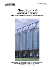
PLANNING THE LOCATION OF LADDER COMPONENTS (cont.)<br />
IF PRESENT, INSIDE LADDERS<br />
SHOULD BE CENTERED ON THE<br />
INSPECTION HATCH<br />
CENTER THE SIDEWALL LADDER ON THE ROOF<br />
LADDER, OR ROOF STAIRS, AS MUCH AS POSSIBLE.<br />
ON STIFFENED BINS, THE POSITION OF THE<br />
SIDEWALL LADDER RELATIVE TO THE UPRIGHTS<br />
CAN BE IMPORTANT (SEE BELOW). IT MAY BE<br />
NECESSARY TO POSITION THE ROOF RELATIVE TO<br />
THE UPRIGHTS WHEN INITIALLY ASSEMBLING TO<br />
AVOID INTERFERENCE WITH THE UPRIGHT.<br />
If there is a ladder/platform combination, it is necessary to position the consecutive sidewall ladder runs<br />
on either side of an upright. The proper side wall bolt holes are illustrated below for a ladder positioned to<br />
the left of the upright. The mirror image of these holes can be used if the ladder is on the right side of the<br />
upright.<br />
LADDER ATTACHMENT<br />
POINTS<br />
UPRIGHT LOCATION<br />
Page 12<br />
PLATFORM ATTACHMENT<br />
POINTS
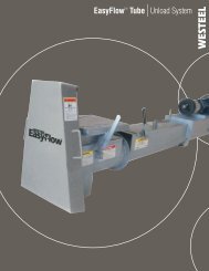
Wall Ladder Assembly Considerations – When mated with a roof stairs, the external ladders, cages and eaves rails<br />
should be assembled as per the assembly instructions contained with those products. However, there are a few additional<br />
requirements as noted below.<br />
1. For 15’ – 54’ Diameter: Bolt on the single ladder extension rung (234098) when assembling the pass through rails to<br />
the top ladder section as shown. The same hardware that is supplied with the ladder package is used. For these bin<br />
diameters, the cage assembly remains as per the instructions provided in the ladder installation manual.<br />
SINGLE LADDER<br />
EXTENSION (234098)<br />
Figure 1<br />
For 60’ – 108’ Diameter: Bolt on the double rung ladder extension (234103) as illustrated below. This double rung<br />
part is an extension of the ladder. The pass through rails (234505), are raised accordingly. For stability both pass<br />
through rails must be secured to the bottom lip of the first roof stair (Figure 4). The support arms (234504) must also<br />
be used as described below. For these bin diameters the top safety cage section only must be extended. See the<br />
illustration for the difference in the top cage section.<br />
54'<br />
60' 108'<br />
60' 108'<br />
Figure 2<br />
Page 13
2. On the side of the roof stair opposite to the inspection hatch location, the support arms (234504) are installed as per<br />
the instructions in the ladder manual, using the support arm clips (234517) and support arm brackets (234518), if the<br />
roof stair is properly centered to the external ladder. Alternatively one support arm can be attached to the stair<br />
stringer, (Figure 3). If there is interference of the support arm that extends inward, with the stair stringer, another<br />
means of properly supporting the pass through rail, inwards and outwards, will need to be developed. The method<br />
proposed in the next step would be adequate.<br />
LADDER<br />
SUPPORT ARMS<br />
(234504)<br />
PASS THROUGH RAILS<br />
(234505)<br />
SUPPORT ARM<br />
BRACKETS (234518)<br />
Figure 3<br />
SUPPORT ARM CLIP<br />
(234517)<br />
3. On the side of the roof stair adjacent to the inspection hatch, the support arms (234504) are used to form part of the<br />
protective cage around the inspection hatch (Figure 27). It is very important that the pass through rail is secured<br />
to the roof structure in an inwards and outwards direction. Pick the location where the pass through rail crosses<br />
the flange of the bottom stair tread. Drill a 3/8” hole completely through the pass rail tube, and through the<br />
flange of the stair tread. Secure using a 3/8” x 4 1/2” fully threaded bolt (150475) that is triple nutted as<br />
shown (Figure 4). Secure the bolt to the pass through rail with one nut, and sandwich the flange on the stair tread<br />
with the remaining 2 nuts. Adjust the relative position of the nuts and tighten to lock into position. If possible, also<br />
secure the second pass through in the manner as well.<br />
PASS THROUGH RAILS<br />
(234505)<br />
STAIR TREAD<br />
Figure 4<br />
Page 14
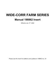
TYPICAL ROOF STAIR <strong>INSTALLATION</strong><br />
(BOTTOM STAIR MODULE SHOWN AS IF INSPECTION HATCH ON RIGHT SIDE OF<br />
STAIRS)<br />
HAND RAIL<br />
STAIR TREAD<br />
SHORT<br />
HANDRAIL<br />
LEFT STRINGER<br />
(BOTTOM FLANGE<br />
POINTS OUTWARD)<br />
HANDRAIL<br />
POST<br />
MIDDLE RAIL (BOTTOM<br />
FLANGES POINT<br />
OUTWARDS)<br />
STRINGER RIGHT<br />
(BOTTOM FLANGES<br />
POINTS OUTWARD)<br />
3/8” x 1” BOLT AND<br />
NUTS (TYPICAL)<br />
3/8” x 1” BOLTS AND<br />
NUTS (TYPICAL)<br />
SHORT MIDDLE RAIL<br />
Z-SHAPE<br />
SUPPORTS<br />
Figure 5<br />
*SHORT HANDRAIL AND MID-RAIL ARE<br />
PROVIDED FOR THE BOTTOM STAIR MODULE<br />
(THIS MODULE IS AT THE LOWERSM POSITION<br />
ON THE ROOF). THE OTHER MODULES CONTAIN<br />
THE REGULAR LENGTH HANDRAILS AND MID-<br />
RAILS (SEE LAYOUT SECTION).<br />
• For larger bin diameters, additional roof stair modules bolt together as shown in the<br />
layout drawings.<br />
• The bottom end of the stair, the short rail and short midrail bolt on the side of the stair<br />
adjacent to the inspection hatch. The mating handrail post is moved forward to<br />
accommodate.<br />
Page 15
ROOF STAIR MODULE LAYOUTS<br />
ROOF STAIRS (in assembly order)<br />
BIN MODEL<br />
STAIR TREAD MODULES<br />
15' 5<br />
18' 7<br />
21' 8<br />
24' 6 5<br />
27' 5 7<br />
30' 7 6<br />
33' 8 7<br />
36' 8 8<br />
39' 5 7 7<br />
42' 7 6 7<br />
45' 6 8 8<br />
48' 8 8 7<br />
51' 5 7 7 7<br />
54' 7 7 7 6<br />
60' 8 8 7 7<br />
66' 6 6 6 8 8<br />
72' 8 8 8 7 7<br />
78' 7 7 7 7 7 7<br />
84' 5 5 7 7 7 7 7<br />
90' 8 8 8 8 8 8<br />
96' 6 6 8 8 8 8 8<br />
102' 7 7 7 7 7 7 7 7<br />
108' 5 5 8 8 8 8 8 8<br />
SHADED MODULE IS THE BOTTOM MODULE (supplied with short hand and mid rails)<br />
NON COMMON PART NUMBERS<br />
DESCRIPTION<br />
5 TREAD 6 TREAD 7 TREAD 8 TREAD<br />
MODULE MODULE MODULE MODULE<br />
STRINGER RIGHT 234059 234057 234055 234053<br />
STRINGER LEFT 234058 234056 234054 234052<br />
HAND RAIL 234065 234066 234067 234068<br />
MIDDLE RAIL 234060 234061 234062 234063<br />
SHORT HAND<br />
RAIL*<br />
234087 234088 234089 234090<br />
SHORT MIDDLE<br />
RAIL*<br />
234071 234072 234073 234074<br />
* SUPPLIED FOR BOTTOM MODULE ONLY<br />
Page 16
<strong>Roof</strong> Stair Assembly – The following assembly instructions should be used in combination with the layouts provided in the<br />
Layout Section for the bin diameter under construction. The layouts provide part numbers, and relative positioning of the<br />
principle components.<br />
1. In general 3/8” x 1” bolts and nuts are used unless<br />
noted otherwise. The best method of construction<br />
would be to conduct as much of the assembly on<br />
the ground, as possible, and then lift the<br />
completed assembly into place and secure to the<br />
bin roof structure.<br />
Z-SECTION BOLTS ON SUCH<br />
THAT THE FLANGE WITH<br />
MULTIPLE SLOTS POINTS DOWN<br />
THE ROOF AND MATES WITH THE<br />
ROOF RIBS.<br />
Figure 6<br />
MATING STRINGER SECTIONS OVERLAP.<br />
BOTTOM FLANGES POINT OUTWARD.<br />
2. If multiple stringer sections are being utilized,<br />
assemble these sections together. Consult the<br />
Layout Section for the bin diameter in question,<br />
for the part numbers being utilized, and the<br />
location of each. Note that there are left and<br />
right stringer section sections and the stringer<br />
flanges point outwards. It is also necessary to<br />
bolt on the stair treads at this time. For the larger<br />
bin diameters with many stair modules it would be<br />
desirable to assemble the stair in manageable<br />
parts and bolt the mating assemblies together as<br />
they are fitted to the roof.<br />
CENTER STAIR<br />
ASSEMBLY ON<br />
UNDERLYING<br />
ROOF PANEL.<br />
Figure 7<br />
3. Z-supports bolt to the stringers at the hole<br />
locations in the bottom flanges. There should be a<br />
Z-support at every hole location. Note that the<br />
flange with the multiple slots is positioned<br />
downwards and mates to the roof ribs. On the<br />
top flange of the Z-support there are three<br />
possible bolting locations. These allow the roof<br />
stairs to be shifted to the right or left in relation to<br />
the underlying roof panels if this is desirable. In<br />
general the center bolting location should be<br />
used. However at the bottom end of the roof<br />
stairs, it may be desirable to shift the Z-<br />
support to the right or left if there is the<br />
possibility of it interfering with the operation<br />
of the inspection hatch, or if it interferes with<br />
the use of the internal ladder sections.<br />
LOWER Z-<br />
SUPPORT<br />
SHIFTED TO<br />
AVOID<br />
INSPECTION<br />
HATCH<br />
Figure 8<br />
Page 17
For 60’ – 108’ Diameter Bins: For bins where there is a step in the roof ribs, there are two sizes of Z-supports to<br />
accommodate the additional height at the bottom of the roof. The standard Z-section (234070) is 4” high. These are<br />
used at the top of the roof. The extended Z-sections (234104) are 7 ⅞” high and are used at the bottom of the roof.<br />
7 ⅞<br />
Figure 9<br />
4. At this time the roof stairs can be mounted to the roof panel. Position the bottom Z-section relative to the bottom<br />
holes in the roof panels. There is flexibility with the fit-up but the bottom stair tread should be positioned close<br />
enough to the pass through rails to permit the bolting of the two pieces together as provided in Step 3 in the External<br />
Ladder Assembly Considerations above. In general, the center of the bottom flange on the Z section is located<br />
6” above the bottom hole in the roof ribs on 15’ to 24’ diameter roofs, and 5” above the bottom hole in the<br />
roof rib for 27’ to 54' diameter roofs. For bin diameters 60’ and larger the Z section is located 12 ¾” above<br />
the bottom edge of the roof rib. In all cases the bottom stair tread should be within 1 to 2" of the ladder pass<br />
through rail. There is some allowance in the slotted holes for side to side movement. For best results center the roof<br />
stair on the roof panel, and on the ladder pass through rails, as much as possible (see section on Timing<br />
Considerations). Drill hole locations into the roof ribs as required and secure with hardware. Putting the sealing<br />
washer on the inside insures a water tight seal. Note: If the layouts are followed correctly, and if the roof stairs are<br />
located properly, there should be no interference between the Z-supports and existing bolt locations along the roof<br />
rib. If this does occur, the complete stair assembly can be moved up or down slightly to avoid these bolt locations.<br />
Alternately the Z sections can be rotated at these locations such that the bottom flange is pointing upwards.<br />
Figure 10<br />
POSITION<br />
BOTTOM STAIR<br />
TREAD WITHIN 1"<br />
TO 2" OF THE<br />
LADDER PASS<br />
THROUGH RAIL<br />
SECURE PASS THROUGH<br />
RAILS TO BOTTOM OF STAIR<br />
TREAD AS PER ITEM 3 IN<br />
PREVIOUS SECTION.<br />
Page 18
5. For extra stability at the top of the stairs, locate the point<br />
where the Z-section protrudes across neighboring roof ribs.<br />
Using the closest slot in the bottom flange of the Z-support as<br />
a guide, drill a 3/8” hole through the underlying rib. Insert a<br />
3/8” x 4 1/2” fully threaded bolt (150475), washers and triple<br />
nut as shown. Secure the bolt to the roof rib with one nut, and<br />
sandwich the flange on the Z-section with the remaining two<br />
nuts. Adjust to take up the slack and tighten to lock in<br />
position. Repeat on the other side, and at other locations<br />
where convenient. Putting a sealing washer (taken from a<br />
3/8” bin bolt) on the inside insures a water tight seal.<br />
FOR EXTRA STABILITY<br />
BOLT THE Z-SECTION<br />
TO OTHER ROOF RIBS<br />
Figure 11<br />
6. Attach the vertical hand rail support C-sections as shown. Consult the Layouts for part numbers and positioning.<br />
There is a long handrail, that goes on the side of the roof stair opposite to the inspection hatch, and a short section,<br />
that goes on the side adjacent to the inspection hatch. The lower vertical hand rail support, on the side of the stair<br />
next to the inspection hatch, is positioned higher up on the stringer to accommodate access to the inspection hatch.<br />
ON THE BOTTOM STAIR MODULE,<br />
THE LONGER HANDRAIL<br />
POSITIONED ON THE NON-<br />
INSPECTION HATCH SIDE<br />
ON THE BOTTOM STAIR<br />
MODULE, THE SHORT<br />
HANDRAIL POSITIONED<br />
ON INSPECTION HATCH<br />
SIDE<br />
Figure 12<br />
ON THE BOTTOM STAIR<br />
MODULE, THE VERTICAL<br />
HANDRAIL SUPPORT ON<br />
INSPECTION HATCH SIDE OF<br />
THE STAIR IS POSITIONED<br />
HIGHER UP, TO ACCOMMODATE<br />
SHORTER HANDRAIL<br />
Page 19
7. Bolt on hand rails and mid rails as shown in the<br />
Typical <strong>Roof</strong> Stair Module Assembly. If multiple<br />
stair modules are being used, mating handrails fit<br />
into each other at the support post locations. One<br />
end of one handrail fits into the other end of the<br />
second handrail as shown. The mid rails are<br />
positioned on the inside of the vertical hand rail<br />
supports, with the “V” positioned as shown.<br />
Mating mid rails also overlap.<br />
MATING HANDRAILS<br />
OVERLAP AT SUPPORT<br />
POST LOCATIONS.<br />
MATING HANDRAILS<br />
OVERLAP AT SUPPORT<br />
POST LOCATIONS.<br />
MATING HANDRAILS<br />
OVERLAP AT SUPPORT<br />
POST LOCATIONS.<br />
Figure 13<br />
Figure 13<br />
8. Attach a warning chain (234101) to a spare hole on the upper end of a hand rail, by securing a bolt through the end<br />
link on the chain. Drape the chain across the stairwell opening and hook into a hole (must be drilled) on the opposite<br />
handrail<br />
HOOK SECURES TO<br />
SPARE HOLE IN<br />
HANDRAIL.<br />
Figure 15<br />
Page 20
Inspection Hatch Cage Assembly (This is supplied as a standard feature of the roof stairs.)<br />
1. Attach three 1” diameter support arms (234504) to the pass through rail adjacent to the inspection hatch as<br />
illustrated, using support arm clips (234517). Position the lowest 1” diameter support arm just above the bend<br />
in the pass through rail, position the top support arm as high as possible and position the center support<br />
arm midway between the other two.<br />
UPPER SUPPORT ARM<br />
POSITIONED AS HIGH AS<br />
POSSIBLE.<br />
PASS THROUGH<br />
RAIL<br />
SUPPORT ARMS<br />
(234504)<br />
PLASTIC CAP<br />
(234559)<br />
SUPPORT ARM CLIPS<br />
MIDDLE SUPPORT<br />
ARM POSITIONED<br />
MID-WAY BETWEEN<br />
UPPER AND LOWER<br />
VERTICAL<br />
SUPPORT TUBE<br />
(234069)<br />
LOWER 1”<br />
DIAMETER<br />
SUPPORT ARM<br />
POSITIONED JUST<br />
ABOVE BEND IN<br />
PASS THROUGH<br />
RAIL.<br />
BOTTOM SUPPORT<br />
ARM (234100)<br />
BOTTOM, LOWER 1 ¼” DIAMTER<br />
SUPPORT ARM POSITIONED<br />
BELOW BEND IN PASS THROUGH<br />
RAIL.<br />
Figure 16<br />
POSITION VERTICAL<br />
SUPPORT TUBE,<br />
DRILL WALL SHEET<br />
TO MATCH AND<br />
SECURE WITH<br />
HARDWARE.<br />
2. Using the support arms as guides, position the vertical support tube (234069) such that it attaches to the other ends<br />
of the support arms using the support arm clips, bridges the eave of the roof panel, and aligns alongside the wall<br />
sheet. Using the holes in the vertical support tube as a guide, drill 3/8” holes through the crest of the mating wall<br />
sheet corrugations and attach using 3/8” x 2 ½” bolts. Putting the sealing washer on the inside insures a water tight<br />
seal. Attach the plastic cap (234559) to the vertical support tube.<br />
Page 21
3. Also bolt on the 1 ¼” diameter, longer, lower support rail (234100) between the pass through rail and the vertical<br />
support tube, again using support arm clips. Position the lower rail lower down on the pass through rail, below<br />
the bend in the pass through rail (Figure 16).<br />
4. When attaching the top support rail to the pass through rail, use the bolt and nut to secure the end link on the<br />
second warning chain (234101). Hook the other end of the chain to a mating hole in the vertical hand rail support<br />
across the opening.<br />
SECOND WARNING<br />
CHAIN (234101)<br />
HARDWARE ON<br />
UPPER SUPPORT<br />
ARM CLIP USED TO<br />
SECURE WARNING<br />
CHAIN<br />
Figure 18<br />
Figure 17<br />
5. Prevent the support arm clips from sliding down the pass<br />
through rail tube and the vertical support tube by securing with<br />
the self drilling screws provided (900461).<br />
SELF DRILLING SCREW<br />
(900461) SECURES SUPPORT<br />
ARM CLIP.<br />
Figure 19<br />
Page 22
6. Attach the final support arm (234504) to the vertical support tube, and to the nearest roof rib, as shown, utilizing the<br />
support arm clip and support arm bracket, as shown. Drill into, and secure to the roof rib as required.<br />
Figure 20<br />
USE SUPPORT ARM AS<br />
BRACE TO SECURE<br />
VERTICAL SUPPORT<br />
TUBE.<br />
ROOF STAIR HARDWARE USAGE<br />
All roof stair and related connections are made using 3/8" x 1" bolts and 3/8" nuts, except for the following:<br />
- Clamps built into Top Cage Hoops secure using 3/8" x 1 ½" bolts<br />
- Pass Through Rails secure to sidewall ladder using 3/8" x 2 ½" bolts (these are supplied with the ladder)<br />
- Vertical Support Tube secures to the wall sheet using 3/8" x 2 ½" bolts<br />
- Pass Through Rails secure to front lip of stair tread using 3/8" x 4 ½" fully threaded bolts and 3 - 3/8" nuts at each<br />
location<br />
- For stability, "Z" supports secure to roof ribs using 3/8" x 4 ½" fully threaded bolts and 3 - 3/8" nuts at each location<br />
- To keep the horizontally placed support arms from slipping down the vertical supports, secure using the #10 x ¾" self<br />
drilling screw<br />
234085 - <strong>Roof</strong> <strong>Stairs</strong> Hardware Package<br />
Part Number Description Quantity<br />
234943 Bolts - 3/8" x 1" (bag of 50) 4<br />
193797 Bolts - 3/8" x 1 1/2" 5<br />
150517 Bolts - 3/8" x 2 1/2" 7<br />
150475 Bolts - 3/8" x 4 1/2" 18<br />
235951 Nuts - 3/8" (bag of 100) 2<br />
900461 Self Drill Screws - #10 x 3/4" 14<br />
234517 Support Arm Clip 7<br />
234559 Pipe Cap 3<br />
234101 Chain 2<br />
<strong>198934</strong> Manual - WC <strong>Roof</strong> <strong>Stairs</strong>1<br />
Page 23
ROOF STAIR PACKAGES<br />
15' 18' 21' 24' 27' 30' 33' 36' 39' 42' 45' 48' 51' 54' 60' 66' 72' 78' 84' 90' 96' 102' 108'<br />
Part No. Description Size Weight 234075 234076 234077 234078 234079 234080 212615 234082 212616 234083 212617 234084 212618 234105 234106 212619 234107 234109 212620 234110 212621 212622 212623<br />
234050 HANDRAIL POST 39.2" 6.7 4 4 4 6 6 6 6 6 8 8 8 8 10 10 10 12 12 14 16 14 16 18 18<br />
234052 STRINGER ‐ 8 TREAD LEFT 104.4" 35 1 1 2 2 2 2 2 3 6 5 6<br />
234053 STRINGER ‐ 8 TREAD RIGHT 104.4" 35 1 1 2 2 2 2 2 3 6 5 6<br />
234054 STRINGER ‐ 7 TREAD LEFT 91.1" 31.9 1 1 1 1 2 2 1 3 3 2 2 6 5 8<br />
234055 STRINGER ‐ 7 TREAD RIGHT 91.1" 31.9 1 1 1 1 2 2 1 3 3 2 2 6 5 8<br />
234056 STRINGER ‐ 6 TREAD LEFT 77.8" 27.2 1 1 1 1 1 3 2<br />
234057 STRINGER ‐ 6 TREAD RIGHT 77.8" 27.2 1 1 1 1 1 3 2<br />
234058 STRINGER ‐ 5 TREAD LEFT 64.5" 22.6 1 1 1 1 1 2 2<br />
234059 STRINGER ‐ 5 TREAD RIGHT 64.5" 22.6 1 1 1 1 1 2 2<br />
234060 MIDDLE RAIL ‐ 5 TREAD 55.1" 6.1 1 2 1 1 1 3 3<br />
234061 MIDDLE RAIL ‐ 6 TREAD 68.4" 7.6 1 2 2 1 2 5 3<br />
234062 MIDDLE RAIL ‐ 7 TREAD 81.7" 9 1 2 1 2 4 3 2 6 5 4 4 11 10 15<br />
234063 MIDDLE RAIL ‐ 8 TREAD 95.0" 10.6 1 1 3 4 3 3 4 5 11 10 12<br />
234064 STAIR TREAD 12" x 24" 7.7 5 7 8 10 11 12 14 15 17 18 20 21 23 24 27 30 34 37 39 43 46 49 51<br />
234065 HANDRAIL ‐ 5 TREAD 55.1" 8.8 1 2 1 1 1 3 3<br />
234066 HANDRAIL ‐ 6 TREAD 68.4" 10.9 1 2 2 1 2 5 3<br />
234067 HANDRAIL ‐ 7 TREAD 81.7" 13 1 2 1 2 4 3 2 6 5 4 4 11 10 15<br />
234068 HANDRAIL ‐ 8 TREAD 95.0" 15.1 1 1 3 4 3 3 4 5 11 10 12<br />
234069 SUPPORT POST 1.66 OD x 79.0" 12.1 1 1 1 1 1 1 1 1 1 1 1 1 1 1 1 1 1 1 1 1 1 1 1<br />
234070 Z‐SUPPORT 4" 48.0" 14.2 2 2 2 3 3 3 3 3 4 4 4 4 5 5 2 2 3 3 3 3 3 4 4<br />
234071 MIDDLE RAIL ‐ 5 TREAD SHORT 37.1" 4.1 1 1 1 1 1 1<br />
234072 MIDDLE RAIL ‐ 6 TREAD SHORT 50.4" 5.6 1 1 1 1<br />
234073 MIDDLE RAIL ‐ 7 TREAD SHORT 63.7" 7.1 1 1 1 1 1 1<br />
234074 MIDDLE RAIL ‐ 8 TREAD SHORT 77.0" 8.5 1 1 1 1 1 1 1<br />
234085 ROOF STAIR HARDWARE PACKAGE 18.82 1 1 1 1 1 1 1 1 1 1 1 1 1 1 1 1 1 1 1 1 1 1 1<br />
234087 HANDRAIL ‐ 5 TREAD SHORT 37.1" 5.9 1 1 1 1 1 1<br />
234088 HANDRAIL ‐ 6 TREAD SHORT 50.4" 8 1 1 1 1<br />
234089 HANDRAIL ‐ 7 TREAD SHORT 63.7" 10.1 1 1 1 1 1 1<br />
234090 HANDRAIL ‐ 8 TREAD SHORT 77.0" 12.2 1 1 1 1 1 1 1<br />
234098 LADDER ‐ SINGLE RUNG 4.8" 1.7 1 1 1 1 1 1 1 1 1 1 1 1 1 1 1 1<br />
234100 SUPPORT ARM ‐ BOTTOM 1.25" OD x 41.9" 3.6 1 1 1 1 1 1 1 1 1 1 1 1 1 1 1 1 1 1 1 1 1 1 1<br />
234103 LADDER ‐ DOUBLE RUNG 15.8" 4.3 1 1 1 1 1 1 1<br />
234104 Z‐SUPPORT 7.87" 48.0" 20.86 3 4 3 4 5 4 5 5 5<br />
234504 SUPPORT ARM 1.0" OD x 36.0" 1.9 2 2 2 2 2 2 2 2 2 2 2 2 2 2 2 2 2 2 2 2 2 2 2<br />
234511 LADDER CAGE ‐ TOP HOOP 5.4 2 2 2 2 2 2 2 2 2<br />
234542BDL LADDER CAGE ‐ VERTICAL BAR BUNDLE 30" 8.4 1 1 1 1 1 1 1 1 1<br />
234543BDL LADDER CAGE ‐ VERTICAL BAR BUNDLE 25" 7.7 1 1 1 1 1 1 1 1 1<br />
235943 BOLT .375 x 1.0 GR8.2 ZJS500 (Bag of 50) 2.55 1 1 2 3 3 4 4 6 6<br />
235951 NUT HEX .375‐16 GR5 ZJS500 (Bag of 100) 1.6 1 1 1 2 2 2 2 3 3
Optional Peak Rail Assembly<br />
The peak rail is an option to the roof stairs and is intended to be assembled to the roof stairs.<br />
1. Bolt the two extensions (234068) to the upper vertical handrail support C-sections on the roof stair (fIGURE<br />
21). Note that these supports should be installed such that the center web of the C-section is on the inside<br />
of the bin (towards the peak ring). The tops of the peak rail extensions protrude about 8 ½” above the<br />
vertical handrail supports. They are bolted on, such that the protruding legs of the angles are on<br />
the inside and pointing towards the peak ring.<br />
EXTENSION<br />
FLANGES<br />
ON INSIDE<br />
EXTENSION (234068)<br />
Figure 21<br />
PEAK<br />
RING<br />
TOP VIEW<br />
CENTER WEB OF HANDRAIL<br />
SUPPORT FACING TOWARDS PEAK RING<br />
VERTICAL HANDRAIL<br />
SUPPORT C-SECTION<br />
2. Preassemble the peak rail support posts (234092) to the support clips (234093) such that when the clips<br />
match the slope of the roof, the support posts are vertical. The flange on the support posts should be<br />
oriented such that the peak rails are attached on the inside of the support posts.<br />
SUPPORT POST FLANGES<br />
ON INSIDE (TOWARDS PEAK RING)<br />
SUPPORT POSTS ARE VERTICAL<br />
Figure 22<br />
3. Using U bolts, loosely secure one peak rail tube to the extensions (234068) that are attached to the roof<br />
stair handrail support posts and the second tube to the mid-point of the handrail support posts. At the<br />
upper location the tubes should butt up against the flange of the extensions. At the mid-point<br />
location, the tubes should not protrude inside of the plane of the handrail support. Once the tubes<br />
have been leveled (as per the following instructions) it is necessary to secure the ends of the tubes using<br />
self-drilling screws at the two locations referred to here. Drill in from the outside of the tubes, through the<br />
pilot holes provided.<br />
Figure 23<br />
BUTT TUBE ENDS<br />
AGAINST EXTENSIONS<br />
BEFORE SECURING<br />
LOWER TUBES SHOULD<br />
NOT PROTRUDE INSIDE<br />
OF SUPPORT POSTS<br />
Page 25
4. The support posts should be roughly distributed among the available roof ribs for the roof in question. Start<br />
with the support post that is across from the roof stairs. Using the peak rail tubes as guides, position this<br />
support post such that it mates with both tubes at the two desired locations. Drill the roof rib to mate with<br />
the holes in the support clip. Secure the support post assembly to the ribs and to the safety tubes. The<br />
support posts should be vertical.<br />
USE THE PEAK RAIL TUBES<br />
LOOSELY SECURED<br />
TO THE ROOF STAIR, TO LOCATE<br />
THE SUPPORT<br />
POST ACROSS FROM THE ROOF<br />
STAIRS.<br />
Figure 24<br />
5. Locate the remaining support posts such that the spaces between them are roughly equal, secure to the<br />
peak rail tubes using the U-bolts. Drill into the roof ribs and secure with the hardware provided.<br />
DISTRIBUTE REMAINING PEAK RING SUPPORT<br />
POSTS EQUALLY AROUND THE ROOF<br />
SECURE ON ROOF RIBS<br />
Figure 25<br />
6. Drill in self drilling screws from the back of the handrail supports and extensions (as per #3) to secure the<br />
end of the peak rail tubes at all four locations<br />
USE SELF DRILLING SCREWS<br />
TO SECURE PEAK RING TUBES<br />
AT ROOF STAIR HAND RAIL<br />
SUPPORT LOCATIONS<br />
Figure 26<br />
Page 26
7. Install pipe plugs (234102) into the end of the peak rail tubes.<br />
8. Tighten all connections<br />
9. Install two support arms (234504) on two support posts at roughly 90º to the roof stairs (one of either side)<br />
to brace the structure laterally. Bolt the support arms to the flange of the support posts and attach the other<br />
end to the roof rib using the support arm brackets (234518)<br />
FASTEN SUPPORT ARMS<br />
TO STIFFEN THE STRUCTURE<br />
Figure 27<br />
Variation: It is possible to install the peak rails independent of the roof stairs. However additional parts will be<br />
required. Two additional peak rail support posts (234092) and two additional support clips (234093) will be required<br />
to secure the ends of the tubes. Also, some means of stiffening these two posts against lateral failure will<br />
also be required. This could be accomplished with two braces (234504) attached to each post flange at<br />
roughly 90º to each other and secured to the roof ribs with support arm brackets (234518).<br />
EXTRA PARTS REQUIRED<br />
234092: SUPPORT POSTS - 2<br />
234093: SUPPORT CLIPS - 2<br />
234504: SUPPORT ARMS - 4<br />
234518: SUPPORT ARM BRACKETS - 4<br />
PROVIDE LATERAL SUPPORT<br />
TO POSTS AT ENTRY POINT<br />
Figure 28<br />
Page 27
PEAK RAIL HARDWARE USAGE<br />
All peak rail connections are made using 3/8” x 1” bolts and 3/8” nuts except for the following:<br />
– Safety tubes are secured to support posts and to the vertical handrail supports on the roof stairs by 5/16” U-<br />
bolts and 5/16” lock nuts<br />
234095 - <strong>Roof</strong> Peak Rail Package (15' to 27' <strong>Roof</strong>s)<br />
Part Number Description Quantity<br />
234091 Ring for 15' - 27' Bins 2<br />
234092 Support Post 5<br />
234097 Hardware Package 1<br />
234504 Support Arm 2<br />
234086 Post Extension 2<br />
234096 - <strong>Roof</strong> Peak Rail Packages (30' to 108' <strong>Roof</strong>s)<br />
Part Number Description Quantity<br />
234094 Ring for 30' - 108' Bins 2<br />
234092 Support Post 7<br />
234097 Hardware Package 1<br />
234504 Support Arm 2<br />
234086 Post Extension 2<br />
234097 - <strong>Roof</strong> Peak Rail Hardware Package<br />
Part Number Description Quantity<br />
235943 Bolt 3/8" x 1" (Bag of 50) 1<br />
234099 Bolt "U"-Round 5/16" 18<br />
235955 Nut - 3/8" 1<br />
900225 Nut - 5/16" Hex Nylon Lock 40<br />
234093 <strong>Roof</strong> Clip 7<br />
234102 Pipe Plug 4<br />
157042 1" Self Drillling Screw 10<br />
234518 Support Arm Bracket 2<br />
<strong>198934</strong> <strong>Roof</strong> Stair Manual 1<br />
Page 28
Optional Peak Platform Assembly<br />
The peak platform is an option to the roof stairs and peak rails, and is to be assembled in conjunction with them.<br />
1. The peak platform support ring is located similar to the peak rail tubes that are provided with the peak rail<br />
assembly, only it is positioned towards the bottom of the peak rail support posts and roof stair handrail<br />
posts. The support ring is secured to the posts using the half-round clips (234114) and ¼” diameter<br />
self drilling screws. First bolt the half-round clips onto all of the posts with the supporting ends facing<br />
inward towards the peak ring. Securely seat the supporting 1.66” dia. tube into the half-round cradles and<br />
secure with a self drilling screw that is drilled in from the backside.<br />
DRILL IN SELF DRILLING<br />
SCREW THROUGH<br />
PILOT HOLE IN THE<br />
POSTS (ALL LOCATIONS)<br />
HALF ROUND<br />
CLIP (234114)<br />
SUPPORT RING<br />
Figure 29<br />
2. The peak platform deck pieces (234118) are evenly distributed around the peak ring as shown such that<br />
the amount of overlap between adjacent pieces is roughly even. The wider end is supported on the<br />
support ring, and the narrow end rests on the ribs of the roof sheets. To initiate the alignment, one deck<br />
piece should be centered on the top roof stair tread. There will be interference between the deck piece and<br />
the skid resistance indentations on the stair tread. The best way to overcome this interference is to shorten<br />
the peak platform deck piece enough to avoid the skid resistance indentations that are on the top surface of<br />
the stair tread. Secure the deck piece to the stair tread with at least two self drilling screws.<br />
SOME INTERFERENCE<br />
WITH THE SKID RESISTANCE<br />
INDENTATIONS ON THE STAIR<br />
TREAD WILL OCCUR IN THIS AREA<br />
Figure 30<br />
Page 29
3. Distribute the remaining deck pieces around the roof such that the amount of overlap between adjacent<br />
pieces is roughly equal. Align the deck pieces such that at least two of the ¼” pilot holes on the wide<br />
end are squarely aligned over the center of the support ring and secure with the self drilling screws.<br />
Figure 31<br />
DISTRIBURE AMOUNT<br />
OF OVERLAP AMOUNG<br />
DECK PIECES<br />
POSITION PILOT HOLES IN DECK<br />
PIECES DIRECTLY OVER SUPPORT<br />
TUBE AND SECURE WITH SELF-<br />
DRILLING SCREWS<br />
4. Position the toe board pieces (234119) such that they loop around the outside circumference of the deck<br />
pieces and bridge between the support posts. Overlap mating toe board pieces at the support post<br />
locations and secure to the support posts using self drilling screws. It may be required to shorten<br />
some of the toe board pieces to prevent unsightly overhang.<br />
SECURE WITH SELF-DRILLING<br />
SCREWS AT ALL POST LOCATIONS<br />
Figure 32<br />
POSITION TOE BOARD<br />
STRIPS SUCH THAT THEY<br />
ARE INSIDE THE OUTER<br />
EDGE OF THE PLATFORM<br />
PIECES<br />
Page 30
Variation: It is possible to install the peak rail and platform independent from the roof stairs. The two additional<br />
support posts and related parts as identified in the previous section will be required. There will be no need to<br />
shorten the one deck piece to avoid interference with the top roof stair tread. However, it will be necessary to<br />
provide a means of supporting the wide end of the one deck piece that would normally be supported by the stair<br />
tread. This can be done by bridging between the two support posts on either side of the entry point. Secure the<br />
deck piece to this support using the self drilling screws.<br />
ADDITIONAL<br />
SUPPORT POSTS<br />
Figure 33<br />
IT WILL BE NECESSARY<br />
TO BRIDGE THIS GAP TO<br />
SUPPORT THE PLATFORM<br />
DECK PIECE<br />
Peak Platform Hardware Usage<br />
All peak Platform connections are made using 3/8” x 1” bolts and nuts except for the following:<br />
− Insure support ring tubes are sitting fully in the half round clips (234114) and secure to the support posts<br />
using ¼” self drilling screws through the pilot hole in each support post<br />
− Secure platform deck pieces using ¼” self drilling screws<br />
− Secure toe boards using ¼” self drilling screws<br />
234115 - Peak Platform 15' - 27' Bins<br />
Part Number Description Quantity<br />
234112 Support Ring - Small 1<br />
234118 Platform Piece 12<br />
234119 Toe Board 3<br />
234117 Hardware 1<br />
234116 - Peak Platform 30' - 108' Bins<br />
Part Number Description Quantity<br />
234113 Support Ring - Large 1<br />
234118 Platform Piece 16<br />
234119 Toe Board 4<br />
234117 Hardware 1<br />
234117 Peak Platform Hardware Package<br />
Part Number Description Quantity<br />
234114 Support Ring Clip 9<br />
235943 Bolt - 3/8" x 1" (Bag of 50) 1<br />
235955 Hex Nut - 3/8" (Bag of 50) 1<br />
157042 1" Self Drilling Screw 100<br />
Page 31
Optional <strong>Roof</strong> Stair Block-Off Assembly<br />
The “<strong>Roof</strong> Stair Block-off Package” is an option that mates with a roof stair package when the<br />
roof stairs is not used in combination with a <strong>Westeel</strong> ladder package. Such would be the case if<br />
the roof stair was being accessed from an overhead conveyor, and there was no wall ladder.<br />
The “Stair Block-off Package” is intended to provide a barrier at the lower end of the roof stair to<br />
prevent somebody from stepping off into space.<br />
Some of the necessary parts are supplied with the roof stair package that forms the “Inspection<br />
Hatch Cage Assembly” (see applicable section). The balance of the parts are supplied as part<br />
of the “<strong>Roof</strong> Stair Block-off Package”.<br />
1. As shown in the diagram position one of the vertical support tubes (234069) such that it<br />
aligns with the inspection hatch roof sheet rib that is furthest away from the roof stair.<br />
The bend in the support tube bridges the eave of the roof sheets and aligns alongside the<br />
top wall sheet. Keep the support pushed up as high as possible. Using the holes in<br />
the support tube as guides, and keeping the support tube in a vertical orientation,<br />
drill 3/8” holes through the crest of the mating wall sheet corrugations and attach<br />
using 3/8” x 2 ½” bolts. Putting the sealing washers on the inside insures a water tight<br />
seal.<br />
USE SUPPORT ARM TO<br />
BRACE VERTICAL SUPPORT<br />
TUBE TO ROOF RIB (BOTH SIDES)<br />
ATTACH THIS VERTICAL<br />
SUPPORT TUBE FIRST IN-LINE<br />
WITH ROOF RIB BESIDE<br />
INSPECTION HATCH.<br />
POSITION SUPPORT<br />
ARMS EQUAL DISTANCE<br />
ALONG VERTICAL SUPPORT<br />
TUBES<br />
SECURE TO TOP<br />
WALL SHEET<br />
Figure 34<br />
SECURE SECOND VERTICAL<br />
TUBE TO STAIR TREAD FLANGE<br />
AT THIS LOCATION<br />
2. Attach four 1” diameter support arms (234504) to the vertical support tube, as illustrated<br />
using support arm clips (234517). Position the lowest just above the bend in the<br />
vertical support tube, position the highest towards the top, and the other two<br />
roughly equal distances apart. Attach a fifth support arm onto the upper portion of the<br />
vertical support tube in the same manner and brace down to the nearest roof rib, as<br />
shown. Secure the lower portion of the support arm with a support arm bracket (234518)<br />
that is secured to the roof rib.<br />
Page 32
3. Using the four support arms as guides, place them horizontally and position a second<br />
vertical support tube such that it attaches to the other end of the support arms using the<br />
support arm clips, bridges the eave of the roof panel and aligns alongside the top wall<br />
sheet. Secure in a similar manner to the first.<br />
4. When attaching the top support arm to the second vertical support tube, use the bolt and<br />
nut to secure the warning chain (234101). Hook the other end of the chain to a mating<br />
hole in the vertical hand rail support across the opening.<br />
HARDWARE ON UPPER<br />
SUPPORT ARM CLIP USED TO<br />
SECURE WARNING CHAIN<br />
Figure 36<br />
Figure 35<br />
5. The second vertical support tube should be positioned in close proximity to the bottom<br />
stair tread on the roof stair. Pick the location where the vertical support tube<br />
crosses the flange of the stair tread and drill a 3/8” hole through both. Secure<br />
using a 3/8” x 4 ½” fully threaded bolt (150475) that is triple nutted as shown.<br />
Secure the bolt to the vertical support tube with one nut, and sandwich the flange on the<br />
stair tread with the remaining two nuts. Adjust the relative position of the nuts and tighten<br />
to lock into position.<br />
VERTICAL SUPPORT<br />
TUBE (234069)<br />
Figure 37<br />
STAIR TREAD<br />
Page 33
6. Attach four more 1” diameter support arms to the second vertical support tube in a similar<br />
manner to # 2 above. Using these as guides, position and secure the third and last<br />
vertical support tube as per # 3 above. Use the last support arm to brace the third<br />
vertical support tube to the roof rib as per # 2 above.<br />
7. Prevent the support arm clips from sliding<br />
down the vertical support tubes by<br />
securing with the self drilling screws<br />
provided (900461).<br />
SELF DRILLING SCREW<br />
(900461) SECURES SUPPORT<br />
ARM CLIP<br />
Figure 38<br />
8. Secure the plastic caps (234559) to the vertical support arm tubes.<br />
<strong>Roof</strong> Stair Block-Off Package Hardware Usage (Note: Required hardware also supplied with<br />
<strong>Roof</strong> Stair Packages):<br />
All <strong>Roof</strong> Stair Block-Off Package connections are made using 3/8” x 1” bolts and 3/8” nuts<br />
except for the following connections.<br />
− Vertical Support Tubes are secured to the grain bin wall sheets using 3/8” x 2 ½” bolts<br />
and nuts<br />
− Secure middle Vertical Support Tube to the bottom Stair Tread using a 3/8” x 4 ½” fully<br />
threaded bolt and triple nutting as shown in the instructions.<br />
− Prevent the support arms from sliding down by securing the support arm clips with self<br />
drilling screws.<br />
<strong>Roof</strong> Stair Block-Off Package (234049)<br />
Part Number Description Quantity<br />
234069 Vertical Support Tube 2<br />
234504 Support Arms 8<br />
234517 Support Arm Clips 13<br />
234518 Support Arm Bracket 2<br />
Page 34
CATWALK ACCESS<br />
Catwalks can be accessed from a roof stair with the aid of a plate fabricated as shown. The plate<br />
can be bolted to the back off any stair tread on the roof stair and then used to support the bottom<br />
of a standard ladder section (234500) which could then tie in with an access point on the catwalk.<br />
Ladder sections must be supported structurally every 44”.<br />
Page 35
APPENDIX I – ROOF STAIR PARTS IDENTIFICATION<br />
“L”<br />
234050 – Handrail Post<br />
Shown Right Stringer, Left is mirrored.<br />
P/N Description "L"<br />
234052 Stringer - 8 Tread Left 104.4<br />
234053 Stringer - 8 Tread Right 104.4<br />
234054 Stringer - 7 Tread Left 91.1<br />
234055 Stringer - 7 Tread Right 91.1<br />
234056 Stringer - 6 Tread Left 77.8<br />
234057 Stringer - 6 Tread Right 77.8<br />
234058 Stringer - 5 Tread Left 66.7<br />
234059 Stringer - 5 Tread Right 66.7<br />
“L”<br />
P/N Description "L"<br />
234060 Middle Rail - 5 Treads 55.1<br />
234061 Middle Rail - 6 Treads 68.4<br />
234062 Middle Rail - 7 Treads 81.7<br />
234063 Middle Rail – 8 Treads 95<br />
234071 Middle Rail – 5 Treads Short 37.1<br />
234072 Middle Rail – 6 Treads Short 50.4<br />
234073 Middle Rail – 7 Treads Short 63.7<br />
234074 Middle Rail – 8 Treads Short 79<br />
234064 – Stair Tread<br />
“L”<br />
P/N Description "L"<br />
234065 Handrail - 5 Treads 55.1<br />
234066 Handrail - 6 Treads 68.4<br />
234067 Handrail - 7 Treads 81.7<br />
234068 Handrail – 8 Treads 95<br />
234087 Handrail – 5 Treads Short 37.1<br />
234088 Handrail – 6 Treads Short 50.4<br />
234089 Handrail – 7 Treads Short 63.7<br />
234090 Handrail - 8 Treads Short 79<br />
234069 – Vertical Support Tube<br />
Page 36
APPENDIX – ROOF STAIR PARTS IDENTIFICATION<br />
234070 – “Z” Support 4”<br />
234098 – Single Rung Ladder<br />
Extension<br />
234100 – Support Arm 1 ¼” Dia<br />
234103 – Double Rung Ladder<br />
Extension<br />
234504 – Support Arm 1” Dia<br />
234104 – “Z” Support 7 ⅞”<br />
234517 – Support Arm Clip<br />
Page 37
APPENDIX II – PEAK RAIL AND PLATFORM PARTS IDENTIFICATION<br />
234086 – Post Extension<br />
234092 – Support Post<br />
234093 – <strong>Roof</strong> Clip<br />
234102 – Pipe Plug<br />
234118 – Platform Piece<br />
234114 – Support Ring Clip<br />
Page 38
APPENDIX II – PEAK RAIL AND PLATFORM PARTS IDENTIFICATION<br />
96<br />
234119 – Platform Toe Board<br />
234518 – Support Arm Bracket<br />
234091 – Peak Rail Tube<br />
85” diameter (1.25” OD Tube) 234094 – Peak Rail Tube<br />
109” diameter (1.25“ OD Tube)<br />
234112 – Peak Platform Support Ring<br />
Small - 85” diameter (1.66” OD Tube)<br />
234113 – Peak Platform Support Ring<br />
Large - 109” diameter (1.66” OD Tube)<br />
Page 39
450 Desautels, P.O. Box 792<br />
Winnipeg, Manitoba CANADA R3C 2N5<br />
Phone: 204-233-7133 Fax: 204-235-0796<br />
www.westeel.com<br />
<strong>Westeel</strong> Division of Vicwest Corporation Printed in Canada