EN.33.C.29_LK Wireless Room Control Cq 1, 4 & 6 ... - LK Systems AB
EN.33.C.29_LK Wireless Room Control Cq 1, 4 & 6 ... - LK Systems AB
EN.33.C.29_LK Wireless Room Control Cq 1, 4 & 6 ... - LK Systems AB

You also want an ePaper? Increase the reach of your titles
YUMPU automatically turns print PDFs into web optimized ePapers that Google loves.
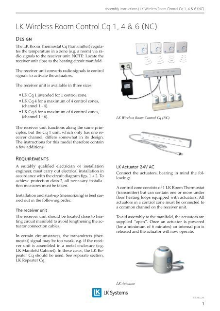
Assembly instructions | <strong>LK</strong> <strong>Wireless</strong> <strong>Room</strong> <strong>Control</strong> <strong>Cq</strong> 1, 4 & 6 (NC)<br />
<strong>LK</strong> <strong>Wireless</strong> <strong>Room</strong> <strong>Control</strong> <strong>Cq</strong> 1, 4 & 6 (NC)<br />
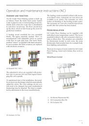
Design<br />
The <strong>LK</strong> <strong>Room</strong> Thermostat <strong>Cq</strong> (transmitter) regulates<br />
the temperature in a zone (e.g. a room) via radio<br />
signals to the receiver unit. NOTE: Locate the<br />
receiver unit close to the heating circuit manifold.<br />
The receiver unit converts radio signals to control<br />
signals to activate the actuators.<br />
The receiver unit is available in three sizes:<br />
• <strong>LK</strong> <strong>Cq</strong> 1 intended for 1 control zone.<br />
• <strong>LK</strong> <strong>Cq</strong> 4 for a maximum of 4 control zones,<br />
(channel 1 - 4).<br />
• <strong>LK</strong> <strong>Cq</strong> 6 for a maximum of 6 control zones,<br />
(channel 1 - 6).<br />
<strong>LK</strong> <strong>Wireless</strong> <strong>Room</strong> <strong>Control</strong> <strong>Cq</strong> (NC).<br />
The receiver unit functions along the same principles,<br />
but the <strong>Cq</strong> 1 unit, which only has one receiver<br />
channel, differs somewhat in its design.<br />
The instructions for this model therefore contain<br />
a few additions.<br />
Requirements<br />
A suitably qualified electrician or installation<br />
engineer, must carry out electrical installation in<br />
accordance with the circuit diagram figs. 1 + 2. To<br />
achieve protection class 2, all necessary installation<br />
measures must be taken.<br />
Installation and start-up (memorizing) is best carried<br />
out in the following order:<br />
The receiver unit<br />
The receiver unit should be located close to heating<br />
circuit manifold to avoid lengthening the actuator<br />
connection cables.<br />
In certain circumstances, the transmitters (thermostat)<br />
signal may be too weak, e.g. if the receiver<br />
unit is assembled in a metal enclosure (e.g.<br />
<strong>LK</strong> Manifold Cabinet). In these cases, the <strong>LK</strong> Repeater<br />
<strong>Cq</strong> should be used. See separate section,<br />
<strong>LK</strong> Repeater <strong>Cq</strong>.<br />
<strong>LK</strong> Actuator 24V AC<br />
Connect the actuators, bearing in mind the following:<br />
A control zone consists of 1 <strong>LK</strong> <strong>Room</strong> Thermostat<br />
(transmitter) but can contain one or more under<br />
floor heating loops equipped with actuators. All<br />
actuators in a control zone must be connected to<br />
a common channel on the receiver unit.<br />
To aid assembly to the manifold, the actuators are<br />
supplied “open”. Once an actuator is powered<br />
(for a minimum of 6 minutes) an internal pin is<br />
released and the actuator will now operate.<br />
<strong>LK</strong> Actuator.<br />
<strong>EN.33.C.29</strong>.<br />
1
Assembly instructions | <strong>LK</strong> <strong>Wireless</strong> <strong>Room</strong> <strong>Control</strong> <strong>Cq</strong> 1, 4 & 6 (NC)<br />
<strong>Cq</strong> 4 and <strong>Cq</strong> 6 <strong>Control</strong> Unit<br />
For the <strong>Cq</strong> 4 and <strong>Cq</strong> 6 Receiver Unit, a maximum<br />
of 4 actuators can be connected to each channel.<br />
The circuit diagram shows that all channels in <strong>Cq</strong><br />
4, and 2 channels in <strong>Cq</strong> 6, have double terminal<br />
boards, b or c respectively, for connecting the actuators.<br />
<strong>Cq</strong> 4 and <strong>Cq</strong> 6 receiver units can operate<br />
a maximum of 16 actuators.<br />
When connecting two or more actuators to the<br />
same channel, the connections must be only to<br />
the double circuit boards.<br />
Supply AC 24V<br />
<strong>LK</strong> Transformer<br />
M<br />
M<br />
Mains AC 230V<br />
Circuit diagram <strong>Cq</strong> 1, (M = Actuator).<br />
2<br />
9<br />
N<br />
Mains<br />
AC 230 V<br />
channel 1 channel 2<br />
a a b b c c<br />
M<br />
a a b b c c 7 8 9<br />
BR3<br />
channel 3 channel 4<br />
a a b b c c a a b b c c<br />
M<br />
<strong>LK</strong> Transformer 230/24 V AC<br />
A transformer 60 VA for 24 V AC supply is connected<br />
in accordance with the circuit diagram for<br />
each receiver unit.<br />
Supply AC 24 V<br />
<strong>LK</strong> Transformer<br />
Circuit diagram <strong>Cq</strong> 4, (M = actuator).<br />
channel 1<br />
channel 2<br />
channel 3<br />
channel 4 channel 5 channel 6<br />
Mains<br />
AC 230 V<br />
a a b b c c a a b b c c 7 8 a b c<br />
M M M<br />
a b c<br />
a b c<br />
a b c<br />
Supply AC 24 V<br />
<strong>LK</strong> Transformer<br />
Circuit diagram <strong>Cq</strong> 6, (M = actuator).<br />
<strong>Cq</strong> 1 Receiver Unit<br />
<strong>Cq</strong> 1 Receiver Unit differs from the other units as<br />
up to eight actuators can be connected.<br />
Up to two actuators can be connected direct to<br />
<strong>Cq</strong>1. However, if necessary, it is possible to connect<br />
up to eight actuators to <strong>Cq</strong>1 by using an external<br />
wiring / junction box. In both cases the<br />
actuators are connected parrallel to each other<br />
and in line between terminal 9 and the <strong>LK</strong> Transformer.<br />
230 V mains voltage connection.<br />
• Connect the receiver unit and the transformer<br />
to the mains.<br />
• Check the primary and secondary voltage.<br />
• Reassemble the protection box on the receiver<br />
unit before Memorizing/Start-up.<br />
<strong>EN.33.C.29</strong>.<br />
2
Assembly instructions | <strong>LK</strong> <strong>Wireless</strong> <strong>Room</strong> <strong>Control</strong> <strong>Cq</strong> 1, 4 & 6 (NC)<br />
Memorizing/activation - Start-up<br />
Reset<br />
Always begin memorizing by first erasing all previous<br />
programming.<br />
For <strong>Cq</strong> 4 and <strong>Cq</strong> 6 as follows:<br />
• Press the ”Reset” button and the button for<br />
”Channel 1” at the same time.<br />
• First release the ”Reset” button, followed by<br />
the ”Channel 1” button.<br />
For <strong>Cq</strong> 1 as follows:<br />
• Press the ”Reset” button and the button !<br />
at the same time.<br />
• First release the ”Reset” button, followed by<br />
the button ! .<br />
• Press ”Reset” again.<br />
<strong>LK</strong> <strong>Room</strong> Thermostat <strong>Cq</strong><br />
Open the door on the room thermostat and remove<br />
the transport protection covering the batteries.<br />
D<br />
C<br />
A<br />
Check the mains switch (A) is in the lower position<br />
towards the heat symbol as shown in the<br />
picture. During memorizing, the thermostat will<br />
attempt to communicate with the activated channel<br />
on the receiver unit. Memorizing can take<br />
place before the thermostat is assembled in the<br />
intended place. The distance between the thermostat<br />
and the receiver should be at least 2 metres<br />
during memorizing.<br />
NOTE:<br />
Mark the thermostat with the channel number that it will<br />
be sent to. (e.g. with tape on the inside of the door.)<br />
Activating the receiver<br />
For <strong>Cq</strong> 4 and <strong>Cq</strong> 6 as follows:<br />
• To activate the memorizing phase on the<br />
receiver unit, press the button for the channel<br />
that is to be activated first. A weak sound<br />
signal is heard and the indicator light will<br />
come on.<br />
For <strong>Cq</strong> 1 as follows:<br />
• To activate the memorizing phase on the<br />
receiver unit, press the button ! . A weak<br />
sound signal is heard and the indicator light<br />
will come on.<br />
Activating the room thermostat<br />
• Press and hold the lower black button (B).<br />
• Briefly press the upper black button (C).<br />
• When the indicator light (D) is lit, release the<br />
lower button. Memorizing (the connection)<br />
between the thermostat and the channel<br />
selected now occur. Pay attention to the receiver.<br />
Once contact is established, the sound<br />
signal will cease and the indicator light will<br />
go out.<br />
• Press the upper button on the room thermostat<br />
one more time to switch off the indicator<br />
light. (The indicator light on the thermostat<br />
in future use is only used to warn of low battery<br />
power.)<br />
B<br />
<strong>EN.33.C.29</strong>.<br />
3
Assembly instructions | <strong>LK</strong> <strong>Wireless</strong> <strong>Room</strong> <strong>Control</strong> <strong>Cq</strong> 1, 4 & 6 (NC)<br />
Function control<br />
Place the room thermostat in the room where it<br />
is intended to be assembled according to the design.<br />
By turning the thermostat’s adjustment dial,<br />
the indicator light on the receiver’s channel will<br />
be lit or switched off respectively within approximately<br />
30 seconds.<br />
• Dial towards maximum temperature, the<br />
light on the receiver unit comes on.<br />
• Dial towards minimum temperature, the<br />
light on the receiver unit goes off.<br />
If the light switches off when it should come on,<br />
check that the mains switch’s setting is in the lower<br />
position towards the heat symbol. See the<br />
section <strong>LK</strong> <strong>Room</strong> Thermostat <strong>Cq</strong>. If the setting<br />
was right and the problem continues, see the section<br />
”Heat/Cool”.<br />
• Do not mount it near a radio, TV or other<br />
transmitter.<br />
• Do not mount it near metal objects, such as<br />
metal doors, metal cupboards or similar.<br />
NOTE:<br />
After fixing to the wall, care must be taken to ensure<br />
buttons A, B & C are correctly located in the front cover;<br />
misalignment will cause malfunctions.<br />
Completing activation / memorizing<br />
Continue activation / memorizing in the same<br />
way as forthe other channels, following the instructions<br />
for the <strong>LK</strong> <strong>Room</strong> Thermostat <strong>Cq</strong>.<br />
<strong>LK</strong> Repeater <strong>Cq</strong><br />
NOTE:<br />
During set up (only) the indicator light on channel 4 or<br />
channel 6 comes on when one or more other channels<br />
trigger the heating. This function continues until all the<br />
channels are activated. For more information, see the<br />
section “Pump <strong>Control</strong>”.<br />
Additional measures<br />
Assembling the room thermostat<br />
Open the room thermostat by pulling the temperature<br />
scale dial right out and loosening the screw<br />
that becomes visible. Bend out the upper part to<br />
the left until it becomes loose. Position the room<br />
thermostat as per the design plan.<br />
For the room thermostat to function properly, the<br />
following guidance should be followed:<br />
• Mount it on an inner wall where it is ventilated<br />
but not in a draught. (NOTE FOR UK: in<br />
some home refurbish- ment projects where<br />
the building is poorly insulated, it may be<br />
prudent to place the thermostat on an outside,<br />
or coldest, wall. The thermostat will then<br />
compensate by calling for heat.)<br />
• Do not expose it to direct sunlight or other<br />
heat sources.<br />
• Mount it approximately 1.5 metres above the<br />
floor.<br />
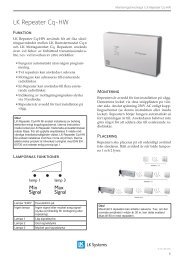
The <strong>LK</strong> Repeater <strong>Cq</strong> is used to increase the transmitting<br />
distance between <strong>LK</strong> <strong>Room</strong> Thermostat<br />
<strong>Cq</strong> and <strong>LK</strong> Receiving Unit <strong>Cq</strong>. The Repeater is<br />
also used when it may be necessary to improve<br />
the quality of transmission, e.g. when affected by<br />
external sources of interference. Place the repeater<br />
in an earthed wall socket. The socket in the repeater<br />
replaces the occupied wall socket. The repeater<br />
will function automatically. The user does<br />
not have to do anything to add the apparatus to<br />
the existing radio links. The repeater should be<br />
located at an appropriate distance from the transmitter.<br />
For more information, see seperate instruction<br />
for <strong>LK</strong> Repeater <strong>Cq</strong>.<br />
<strong>EN.33.C.29</strong>.<br />
4
Assembly instructions | <strong>LK</strong> <strong>Wireless</strong> <strong>Room</strong> <strong>Control</strong> <strong>Cq</strong> 1, 4 & 6 (NC)<br />
Pump control for <strong>Cq</strong> 4 and <strong>Cq</strong> 6<br />
The last channels on the receiver <strong>Cq</strong> 4 (channel 4)<br />
and <strong>Cq</strong> 6 (channel 6) can start or stop a circulating<br />
pump. However, <strong>Cq</strong> 4 becomes 3 channel<br />
and <strong>Cq</strong> 6, 5 channel receiver. Pump control can be<br />
arranged via an external relay for 24/230 V (relay<br />
not supplied by <strong>LK</strong>). The 24 Vside of the relay<br />
should be connected to terminals A and C of the<br />
channels. The channels have a time delay of 10<br />
minutes for pump control.<br />
Range control of radio signal<br />
To determine a connection’s maximum range, the<br />
following check can be carried out:<br />
• First, carry out activation/memorizing as the<br />
instructions.<br />
• Then push the “Reset” button on the receiver<br />
unit at the same time as the button for<br />
“Channel 2”.<br />
• First release “Reset” followed by the “Channel<br />
2” button. The sound signal and the<br />
indicator light will now pulse for about 2<br />
seconds on, 8 seconds off.<br />
• Next move the room thermostat far enough<br />
away from the receiver unit that the pulses<br />
almost stop. This is the maximum distance<br />
for radio connection.<br />
• Finish the check by pressing “Reset” on the<br />
receiver unit.<br />
The room thermostat returns to normal operation<br />
mode after a short time. Other channels are not<br />
affected by the check. If the connection is insufficient,<br />
the radio signal can be strengthened with<br />
<strong>LK</strong> Repeater <strong>Cq</strong>. See separate section, <strong>LK</strong> Repeater<br />
<strong>Cq</strong>.<br />
Heating & Cooling<br />
The equipment is constructed so that it can be<br />
used to heat(under floor heating) and cool. The<br />
functions are changed manually. When supplied,<br />
the components are set for heat. Switching to cool<br />
can be done in two ways.<br />
Alternative 1<br />
Change all room thermostats by moving the<br />
mains switchA to the upper position.<br />
Alternative 2<br />
Changing the whole installation by reprogramming<br />
the receiver unit as follows:<br />
Change to cool (summer operation):<br />
• Press the “Reset” button and the button for<br />
”Channel 3” at the same time.<br />
• First release “Reset” followed by “Channel<br />
3”.<br />
Change to heat (winter operation):<br />
• Press the “Reset” button and the button for<br />
”Channel 4” at the same time.<br />
• First release “Reset” followed by ”Channel<br />
4”.<br />
NOTE:<br />
For the <strong>Cq</strong> 1 unit, the change is made on the room thermostat.<br />
Alarm<br />
When a fault occurs, the indicator light begins to<br />
flash with an irregular time interval and a sound<br />
signal is heard. During signal disruption, the affected<br />
channel will deliver approximately 30%<br />
heat output.<br />
Temporary interruption<br />
If no signal is received from the room thermostat<br />
(transmitter) for a period between 1 to 10 hours,<br />
the indicator light on the receiver unit will display<br />
short flashes, but no sound signal. Acknowledgment<br />
of the alarm occurs automatically if the<br />
transmitter signal reoccurs.<br />
Prolonged interruption<br />
If no signal is received from the room thermostat<br />
(transmitter) for a period of more than 10 hours,<br />
the indicator light on the receiver unit will display<br />
short flashes and a sound signal is emitted.<br />
Acknowledgment of the alarm occurs automatically<br />
if the transmitter signal is regained. In the<br />
event of a loss of power in the receiver unit, no<br />
programming will be affected. Operation will<br />
continue as normal once power is restored.<br />
<strong>EN.33.C.29</strong>.<br />
5
Assembly instructions | <strong>LK</strong> <strong>Wireless</strong> <strong>Room</strong> <strong>Control</strong> <strong>Cq</strong> 1, 4 & 6 (NC)<br />
Acknowledgment of the alarm<br />
To acknowledge a disruption, interrupt “Memorizing”,<br />
or end a connection test, press “Reset” on<br />
the receiver unit. The output will return to the basic<br />
position. When the next control signal comes<br />
after approximately 10 - 20 minutes, the output<br />
will return to its correct position. Any radio connection<br />
established will not be affected.<br />
Valve exercising<br />
The actuator disconnects once a day for 3 minutes<br />
and opens the valve on the heating circuit<br />
distributor. This function prevents valves from<br />
sticking, for instance, during the summer period.<br />
If valve exercising is not required, this function<br />
can be disconnected using vertical 1 in the room<br />
thermometer. Remove the temperature dial, loosen<br />
the screw and liftthe cover. Remove vertical 1,<br />
which is marked with BR1 on the printed circuit<br />
card.<br />
Description of functions - room thermostat<br />
<strong>Control</strong> occurs using pulse width modulation<br />
(PBM), whichis intended for actuators. The control<br />
signal, which is calcu-lated from the difference<br />
between the actual temperatureand the temperature<br />
entered, is emitted in the form of asignal<br />
with different pulse and rest ratios. The sum of<br />
the signal and rest period is always 10 minutes.<br />
With large temperature variations, the thermostat<br />
is constantly switching on or off.<br />
Changing the batteries on the room thermostat<br />
When the indicator light flashes with 15-second<br />
intervals, the batteries should be changed within<br />
a few days. The batteries are located under the<br />
battery cover. For information about battery type,<br />
see “Technical data.”<br />
Connection check<br />
After using the receiver unit’s “Reset” function,<br />
the respective channel’s indicator light will indicate,<br />
by a shortflash, that the connection has been<br />
established.<br />
Technical data for receiver<br />
<strong>Cq</strong>1, <strong>Cq</strong>4 & <strong>Cq</strong>6<br />
Supply voltage<br />
AC 230 V + 24 V, 50/60 HZ<br />
Power requirement Approx. 3 VA for <strong>Cq</strong> 4 - 6<br />
Approx. 12 VA for <strong>Cq</strong> 1<br />
Operating temperature 0 - +50 °C<br />
Storage temperature -20 - +60 °C<br />
Disconnecting sound signal Vertical BR1 for <strong>Cq</strong> 4 - 6<br />
Vertical J2 for <strong>Cq</strong> 1<br />
Aerial<br />
Internal<br />
Reception frequency 868 MHz<br />
Protection mode IP 40<br />
Protection class 2<br />
Output signal, type Relay, 1 alternating potential<br />
free<br />
AC 24 V - 230 V for<br />
<strong>Cq</strong> 4 - 6<br />
AC 24 V - 230 V for<br />
<strong>Cq</strong> 1<br />
Number of actuators<br />
AC 24 V 2-3 VA NC, which<br />
can be controlled per relay<br />
output<br />
Maximum number of actuators<br />
within same receiver<br />
unit<br />
Max 8 A cos φ = 1<br />
Max 2 A cos φ = 0,6<br />
Max 16 A cos φ = 1<br />
Max 2 A cos φ = 0,6<br />
For <strong>Cq</strong> 4 - 6 = 4<br />
For <strong>Cq</strong> 1 = 8<br />
NOTE:<br />
Trouble free operation cannot always be guaranteed due<br />
to possible external interference sources.<br />
16<br />
After changing the batteries, the thermostat will<br />
continue to operate according to the chosen mode<br />
of operation. With depleted batteries, the receiver<br />
channel will continuously deliver 30 % heat output.<br />
<strong>EN.33.C.29</strong>.<br />
6
Assembly instructions | <strong>LK</strong> <strong>Wireless</strong> <strong>Room</strong> <strong>Control</strong> <strong>Cq</strong> 1, 4 & 6 (NC)<br />
Technical data for transmitter<br />
Type designation<br />
Setting range +5 - +30 °C<br />
<strong>LK</strong> <strong>Room</strong> Thermostat <strong>Cq</strong><br />
Supply voltage 2 x 1.5V batteries = 3V,<br />
alkaline (LR03)<br />
Battery life<br />
Approximately 3 years<br />
<strong>Control</strong> function<br />
PBM (optional 2 point)<br />
Cycle time<br />
Approximately 10 minutes<br />
(total on and off time)<br />
Measurement interval Approximately 10 minutes<br />
Type<br />
Heat/Cool<br />
Valve exercising<br />
Once a day for 3 minutes<br />
(can be switched off, BR1)<br />
Temperature sensor NTC<br />
Transfer frequency 868 MHz<br />
Modulation<br />
FM<br />
Aerial<br />
Intern<br />
Transmission interval < 10 minutes<br />
Range (typical) 100 metres free air or 2<br />
floors or 3 walls<br />
Protection mode IP 40<br />
Protection class 2<br />
Operating temperature -25 - +40 °C<br />
Storage temperature -25 - +70 °C<br />
Temperature limit<br />
On the adjustment dial<br />
4<br />
60<br />
75<br />
27,1<br />
<strong>LK</strong> <strong>Room</strong> Thermostat <strong>Cq</strong>.<br />
71 26,8<br />
4<br />
60<br />
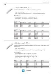
Measurements<br />
<strong>LK</strong> Receiver Unit <strong>Cq</strong> 1.<br />
2,2<br />
50,2<br />
40<br />
4,3<br />
62,5<br />
372<br />
247<br />
2,5<br />
57<br />
<strong>LK</strong> Receiver Unit <strong>Cq</strong> 4.<br />
2,2<br />
50,2<br />
40<br />
4,3<br />
97,5<br />
452<br />
252<br />
2,5<br />
57<br />
<strong>LK</strong> Receiver Unit <strong>Cq</strong> 6.<br />
<strong>EN.33.C.29</strong>.<br />
7