a literature survey on z-source inverter - vsrd international journals ...
a literature survey on z-source inverter - vsrd international journals ...
a literature survey on z-source inverter - vsrd international journals ...

You also want an ePaper? Increase the reach of your titles
YUMPU automatically turns print PDFs into web optimized ePapers that Google loves.
VSRD Internati<strong>on</strong>al Journal of Electrical, Electr<strong>on</strong>ics & Communicati<strong>on</strong> Engineering, Vol. 2 No. 11 November 2012 / 889<br />
ISSN No. 2231-3346 (Online), 2319-2232 (Print) © VSRD Internati<strong>on</strong>al Journals : www.<strong>vsrd</strong><strong>journals</strong>.com<br />
REVIEW ARTICLE<br />
A LITERATURE SURVEY ON Z-SOURCE INVERTER<br />
1Vrushali Suresh Neve, 2 P.H. Zope* and 3 S.R. Suralkar<br />
1Research Scholar, 2 Professor, 3 Professor &HOD, 1,2,3 Department of Electr<strong>on</strong>ics & Tele-Communicati<strong>on</strong> Engineering,<br />
SSBT’s College of Engineering & Technology, Jalga<strong>on</strong>, Maharashtra, INDIA.<br />
*Corresp<strong>on</strong>ding Author : phzope@gmail.com<br />
ABSTRACT<br />
This paper presents an impedance-<strong>source</strong> (or impedance-fed) power c<strong>on</strong>verter (abbreviated as Z-<strong>source</strong> c<strong>on</strong>verter) (ZSC) and its c<strong>on</strong>trol<br />
method for implementing dc-to-ac, ac-to-dc, ac-to-ac, and dc-to-dc power c<strong>on</strong>versi<strong>on</strong>. The Z-<strong>source</strong> c<strong>on</strong>verter employs a unique impedance<br />
network (or circuit) to couple the c<strong>on</strong>verter main circuit to the power <strong>source</strong>, thus providing unique features that cannot be obtained in the<br />
traditi<strong>on</strong>al voltage-<strong>source</strong> (or voltage-fed) c<strong>on</strong>verter (VSC) and current-<strong>source</strong> (or current-fed) c<strong>on</strong>verter (CSC) where a capacitor and<br />
inductor are used, respectively. The Z-<strong>source</strong> c<strong>on</strong>verter (ZSC) overcomes the c<strong>on</strong>ceptual and theoretical barriers and limitati<strong>on</strong>s of the<br />
traditi<strong>on</strong>al voltage-<strong>source</strong> c<strong>on</strong>verter (abbreviated as V-<strong>source</strong> c<strong>on</strong>verter) and current-<strong>source</strong> c<strong>on</strong>verter (abbreviated as I-<strong>source</strong> c<strong>on</strong>verter)<br />
and provides a novel power c<strong>on</strong>versi<strong>on</strong> c<strong>on</strong>cept. The Z-<strong>source</strong> c<strong>on</strong>cept can be applied to all dc-to-ac, ac-to-dc, ac-to-ac, and dc-to-dc power<br />
c<strong>on</strong>versi<strong>on</strong>.<br />
Keywords : Voltage Source Inverter, Current Source Inverter, Z-Source Inverter.<br />
1. INTRODUCTION<br />
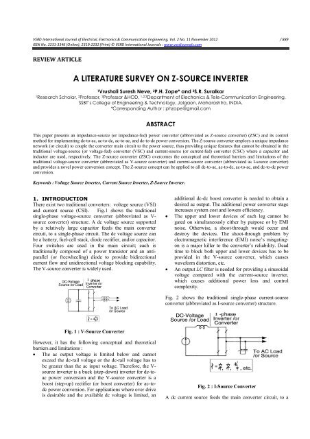
There exist two traditi<strong>on</strong>al c<strong>on</strong>verters: voltage <strong>source</strong> (VSI)<br />
and current <strong>source</strong> (CSI). Fig.1 shows the traditi<strong>on</strong>al<br />
single-phase voltage-<strong>source</strong> c<strong>on</strong>verter (abbreviated as V-<br />
<strong>source</strong> c<strong>on</strong>verter) structure. A dc voltage <strong>source</strong> supported<br />
by a relatively large capacitor feeds the main c<strong>on</strong>verter<br />
circuit, to a single-phase circuit. The dc voltage <strong>source</strong> can<br />
be a battery, fuel-cell stack, diode rectifier, and/or capacitor.<br />
Four switches are used in the main circuit; each is<br />
traditi<strong>on</strong>ally composed of a power transistor and an antiparallel<br />
(or freewheeling) diode to provide bidirecti<strong>on</strong>al<br />
current flow and unidirecti<strong>on</strong>al voltage blocking capability.<br />
The V-<strong>source</strong> c<strong>on</strong>verter is widely used.<br />
<br />
<br />
additi<strong>on</strong>al dc-dc boost c<strong>on</strong>verter is needed to obtain a<br />
desired ac output. The additi<strong>on</strong>al power c<strong>on</strong>verter stage<br />
increases system cost and lowers efficiency.<br />
The upper and lower devices of each leg cannot be<br />
gated <strong>on</strong> simultaneously either by purpose or by EMI<br />
noise. Otherwise, a shoot-through would occur and<br />
destroy the devices. The shoot-through problem by<br />
electromagnetic interference (EMI) noise’s misgating<strong>on</strong><br />
is a major killer to the c<strong>on</strong>verter’s reliability. Dead<br />
time to block both upper and lower devices has to be<br />
provided in the V-<strong>source</strong> c<strong>on</strong>verter, which causes<br />
waveform distorti<strong>on</strong>, etc.<br />
An output LC filter is needed for providing a sinusoidal<br />
voltage compared with the current-<strong>source</strong> <strong>inverter</strong>,<br />
which causes additi<strong>on</strong>al power loss and c<strong>on</strong>trol<br />
complexity.<br />
Fig. 2 shows the traditi<strong>on</strong>al single-phase current-<strong>source</strong><br />
c<strong>on</strong>verter (abbreviated as I-<strong>source</strong> c<strong>on</strong>verter) structure.<br />
Fig. 1 : V-Source C<strong>on</strong>verter<br />
However, it has the following c<strong>on</strong>ceptual and theoretical<br />
barriers and limitati<strong>on</strong>s :<br />
The ac output voltage is limited below and cannot<br />
exceed the dc-rail voltage or the dc-rail voltage has to<br />
be greater than the ac input voltage. Therefore, the V-<br />
<strong>source</strong> <strong>inverter</strong> is a buck (step-down) <strong>inverter</strong> for dc-toac<br />
power c<strong>on</strong>versi<strong>on</strong> and the V-<strong>source</strong> c<strong>on</strong>verter is a<br />
boost (step-up) rectifier (or boost c<strong>on</strong>verter) for ac-todc<br />
power c<strong>on</strong>versi<strong>on</strong>. For applicati<strong>on</strong>s where over drive<br />
is desirable and the available dc voltage is limited, an<br />
Fig. 2 : I-Source C<strong>on</strong>verter<br />
A dc current <strong>source</strong> feeds the main c<strong>on</strong>verter circuit, to a
Vrushali Suresh Neve, P.H. Zope and S.R. Suralkar VSRDIJEECE, Vol. II (XI), 2012 / 890<br />
single-phase. The dc current <strong>source</strong> can be a relatively large<br />
dc inductor fed by a voltage <strong>source</strong> such as a battery, fuelcell<br />
stack, diode rectifier, or thyristor c<strong>on</strong>verter. Four<br />
switches are used in the main circuit; each is traditi<strong>on</strong>ally<br />
composed of a semic<strong>on</strong>ductor switching device with reverse<br />
block capability such as a gate-turn-off thyristor (GTO) and<br />
SCR or a power transistor with a series diode to provide<br />
unidirecti<strong>on</strong>al current flow and bidirecti<strong>on</strong>al voltage<br />
blocking.<br />
However, the I-<strong>source</strong> c<strong>on</strong>verter has the following<br />
c<strong>on</strong>ceptual and theoretical barriers and limitati<strong>on</strong>s :<br />
The ac output voltage has to be greater than the original<br />
dc voltage that feeds the dc inductor or the dc voltage<br />
produced is always smaller than the ac input voltage.<br />
Therefore, the I-<strong>source</strong> <strong>inverter</strong> is a boost <strong>inverter</strong> for<br />
dc-to-ac power c<strong>on</strong>versi<strong>on</strong> and the I-<strong>source</strong> c<strong>on</strong>verter is<br />
a buck rectifier (or buck c<strong>on</strong>verter) for ac-to-dc power<br />
c<strong>on</strong>versi<strong>on</strong>. For applicati<strong>on</strong>s where a wide voltage<br />
range is desirable, an additi<strong>on</strong>al dc–dc buck (or boost)<br />
c<strong>on</strong>verter is needed. The additi<strong>on</strong>al power c<strong>on</strong>versi<strong>on</strong><br />
stage increases system cost and lowers efficiency.<br />
At least <strong>on</strong>e of the upper devices and <strong>on</strong>e of the lower<br />
devices have to be gated <strong>on</strong> and maintained <strong>on</strong> at any<br />
time. Otherwise, an open circuit of the dc inductor<br />
would occur and destroy the devices. The open-circuit<br />
problem by EMI noise’s misgating-off is a major<br />
c<strong>on</strong>cern of the c<strong>on</strong>verter’s reliability. Overlap time for<br />
safe current commutati<strong>on</strong> is needed in the I-<strong>source</strong><br />
c<strong>on</strong>verter, which also causes waveform distorti<strong>on</strong>, etc.<br />
The main switches of the I-<strong>source</strong> c<strong>on</strong>verter have to<br />
block reverse voltage that requires a series diode to be<br />
used in combinati<strong>on</strong> with high-speed and highperformance<br />
transistors such as insulated gate bipolar<br />
transistors (IGBTs). This prevents the direct use of lowcost<br />
and high-performance IGBT modules and<br />
intelligent power modules (IPMs).<br />
In additi<strong>on</strong>, both the V-<strong>source</strong> c<strong>on</strong>verter and the I-<strong>source</strong><br />
c<strong>on</strong>verter have the following comm<strong>on</strong> problems :<br />
1. They are either a boost or a buck c<strong>on</strong>verter and<br />
cannot be a buck–boost c<strong>on</strong>verter. That is, their obtainable<br />
output voltage range is limited to either greater or smaller<br />
than the input voltage.<br />
2. Their main circuits cannot be interchangeable. In<br />
other words, neither the V-<strong>source</strong> c<strong>on</strong>verter main circuit can<br />
be used for the I-<strong>source</strong> c<strong>on</strong>verter, nor vice versa.<br />
3. They are vulnerable to EMI noise in terms of<br />
reliability.<br />
impedance-fed) power c<strong>on</strong>verter (abbreviated as Z-<strong>source</strong><br />
c<strong>on</strong>verter) and its c<strong>on</strong>trol method for implementing dc-toac,<br />
ac-to-dc, ac-to-ac, and dc-to-dc power c<strong>on</strong>versi<strong>on</strong>. Fig.3<br />
shows the general Z-<strong>source</strong> c<strong>on</strong>verter structure. It employs<br />
a unique impedance network (or circuit) to couple the<br />
c<strong>on</strong>verter main circuit to the power <strong>source</strong>, load, or another<br />
c<strong>on</strong>verter, for providing unique features that cannot be<br />
observed in the traditi<strong>on</strong>al Voltage and current <strong>source</strong><br />
c<strong>on</strong>verters where a capacitor and inductor are used,<br />
respectively. The Z-<strong>source</strong> c<strong>on</strong>verter overcomes limitati<strong>on</strong>s<br />
of the traditi<strong>on</strong>al voltage <strong>source</strong> c<strong>on</strong>verter and current<br />
<strong>source</strong> c<strong>on</strong>verter and provides a novel power c<strong>on</strong>versi<strong>on</strong><br />
c<strong>on</strong>cept.<br />
Fig. 3 : General Structure of the Z-Source C<strong>on</strong>verter<br />
Fig. 4 : Z-Source C<strong>on</strong>verter Structure Using the Anti-<br />
Parallel Combinati<strong>on</strong> of Switching Device and Diode<br />
2. Z-SOURCE CONVERTER<br />
The Z-<strong>source</strong> c<strong>on</strong>verter (ZSC) is a newly proposed power<br />
c<strong>on</strong>versi<strong>on</strong> c<strong>on</strong>cept that is very promising in the above<br />
menti<strong>on</strong>ed areas of power c<strong>on</strong>diti<strong>on</strong>ing especially in<br />
alternative energy <strong>source</strong>s and distributed generati<strong>on</strong>. To<br />
overcome the problems of the traditi<strong>on</strong>al voltage <strong>source</strong> and<br />
current <strong>source</strong> c<strong>on</strong>verters, in this an impedance-<strong>source</strong> (or<br />
Fig. 5 : Z-Source C<strong>on</strong>verter Structure Using the Series<br />
Combinati<strong>on</strong> of Switching Device and Diode
Vrushali Suresh Neve, P.H. Zope and S.R. Suralkar VSRDIJEECE, Vol. II (XI), 2012 / 891<br />
In Fig.3, a two-port network that c<strong>on</strong>sists of a split-inductor<br />
L1 and L2 and capacitors C1 and C2 and c<strong>on</strong>nected in X<br />
shape is employed to provide an impedance <strong>source</strong> (Z<strong>source</strong>)<br />
coupling the c<strong>on</strong>verter (or <strong>inverter</strong>) to the dc <strong>source</strong>,<br />
load, or another c<strong>on</strong>verter. The dc <strong>source</strong>/or load can be<br />
either a voltage or a current <strong>source</strong>/or load. Therefore, the<br />
dc <strong>source</strong> can be a battery, diode rectifier, thyristor<br />
c<strong>on</strong>verter, fuel cell, an inductor, a capacitor, or a<br />
combinati<strong>on</strong> of those. Switches used in the c<strong>on</strong>verter can be<br />
a combinati<strong>on</strong> of switching devices and diodes such as the<br />
anti-parallel combinati<strong>on</strong> as shown in Fig.4, the series<br />
combinati<strong>on</strong> as shown in Fig.5 As examples, Fig 4 & 5.<br />
Shows two single-phase Z-<strong>source</strong> <strong>inverter</strong> c<strong>on</strong>figurati<strong>on</strong>s.<br />
The inductance and capacitance can be provided through a<br />
split inductor or two separate inductors. The Z-<strong>source</strong><br />
c<strong>on</strong>cept can be applied to all dc-to-ac, ac-to-dc, ac-to-ac,<br />
and dc-to-dc power c<strong>on</strong>versi<strong>on</strong>.<br />
3. Z-SOURCE INVERTER<br />
Z-<strong>source</strong> <strong>inverter</strong> (ZSI) which is based <strong>on</strong> Z-<strong>source</strong> network<br />
can buck and boost the output AC voltage, which is not<br />
possible using traditi<strong>on</strong>al voltage <strong>source</strong> or current <strong>source</strong><br />
<strong>inverter</strong>s.<br />
Also the ZSI has the unique ability to allow the dc-link of<br />
the <strong>inverter</strong> to be shorted, which is not possible in the<br />
traditi<strong>on</strong>al voltage <strong>source</strong> <strong>inverter</strong>s. This improves the<br />
reliability of the circuit .Actually c<strong>on</strong>cept of boosting the<br />
input voltage is based <strong>on</strong> the ratio of “shoot-through” time<br />
to the whole switching period.<br />
Z-<strong>source</strong> c<strong>on</strong>verter is shown in Fig.6 where an impedance<br />
network is placed between d.c. link and <strong>inverter</strong>. Z-<strong>source</strong><br />
<strong>inverter</strong> (ZSI) provides a greater voltage than the d.c. link<br />
voltage. It reduces the inrush current & horm<strong>on</strong>ics in the<br />
current because of two inductors in z <strong>source</strong> network. It<br />
forms a sec<strong>on</strong>d order filter &handles the undesirable voltage<br />
sags of the d.c. voltage <strong>source</strong>.<br />
Fig. 7 : Single Phase Z-Source Inverter<br />
Fig. 7 shows a topology of the single phase Z-<strong>source</strong><br />
<strong>inverter</strong>, where the impedance network is placed between<br />
the power <strong>source</strong> and the single phase <strong>inverter</strong> .The<br />
presence of 2 inductors & 2 capacitors in Z-<strong>source</strong> network,<br />
allows both switches of same phase leg ON state<br />
simultaneously, called as shoot-through state & gives<br />
boosting capability to the <strong>inverter</strong> without damaging the<br />
switching devices. During shoot through state energy is<br />
transferred From capacitor To inductor & hence Z-<strong>source</strong><br />
<strong>inverter</strong>( ZSI) gains the voltage boosting capability .Diode is<br />
required to prevent the discharge of overcharged Capacitor<br />
through the <strong>source</strong>.<br />
4. SWITCHING STATES OF A SINGLE<br />
PHASE Z-SOURCE INVERTER<br />
Switching<br />
Output<br />
S1 S2 S3 S4<br />
States<br />
Voltage<br />
Active<br />
States<br />
Zero<br />
States<br />
1 0 0 1 Finite<br />
0 1 1 0 Voltage<br />
1 0 1 0<br />
0 1 0 1<br />
Zero<br />
Shoot<br />
Through<br />
States<br />
1 1 S3 S4<br />
S1 S2 1 1<br />
1 1 1 1<br />
Zero<br />
Fig. 6 : Z-Source Inverter<br />
As shown in table, a single phase Z-<strong>source</strong> <strong>inverter</strong> has five<br />
possible switching states: two active states (vectors) when<br />
the dc voltage is c<strong>on</strong>nected across the load, two zero states<br />
(vectors) when the load terminals are shorted through either<br />
the lower or the upper two switches and <strong>on</strong>e shoot through<br />
state (vector) when the load terminals are shorted through<br />
both the upper and the lower switches of any <strong>on</strong>e leg or two<br />
legs. These switching states and their combinati<strong>on</strong>s<br />
introduce a new PWM method for the Z- Source <strong>inverter</strong> [2,<br />
7, 12].
Vrushali Suresh Neve, P.H. Zope and S.R. Suralkar VSRDIJEECE, Vol. II (XI), 2012 / 892<br />
Fig.8 shows the operating states of the single phase Z-<br />
<strong>source</strong> <strong>inverter</strong> in shoot through states that two switches of<br />
<strong>on</strong>e phase leg or two phase legs are turned <strong>on</strong><br />
simultaneously.<br />
v i = V c -V L = 2V C - V dc … (4)<br />
Therefore the average DC-link voltage across the <strong>inverter</strong><br />
bridge over <strong>on</strong>e switching cycle (T) is:<br />
… (5)<br />
By applying T 1 = T -T O in Eq.5:<br />
… (6)<br />
Where Do is the shoot through duty cycle and Vd, is the<br />
input voltage <strong>source</strong>.<br />
5. SINGLE-PHASE Z-SOURCE INVERTER<br />
TOPOLOGY<br />
There are two basic Z-<strong>source</strong> c<strong>on</strong>verter topologies,<br />
including voltage-fed and current-fed, as shown in Fig.9.<br />
The Z-<strong>source</strong> networks are symmetric in these topologies. S 1<br />
and S 2 are turned <strong>on</strong> and off in complement. Defining the<br />
duty ratio of S 1 as D, then we can get the relati<strong>on</strong>ship<br />
between voltage ratio and D of voltage-fed and current-fed<br />
topologies, respectively:<br />
Fig. 8 : Operating Modes of a Single Phase Z-Source<br />
Inverter (A) Shoot through Zero State (B) N<strong>on</strong> Shoot<br />
through States<br />
… (7)<br />
In Fig.8-a, a diode placed at the input side is reverse biased<br />
and the capacitors charge the inductors [9] and the voltage<br />
across the inductors is:<br />
V L1 = V C1 , V L2 =V C2 … (1)<br />
With the assumpti<strong>on</strong> of symmetric impedance network (C 1 =<br />
C 2 =C and L 1 =L 2 =L), it can be observed that V L1 = V L2 = V L<br />
and I L1 = I L2 =I L and the DC-link voltage across the <strong>inverter</strong><br />
bridge during a shoot through interval (To ) is:<br />
v i = 0 … (2)<br />
Fig.8-b shows the Z-<strong>source</strong> <strong>inverter</strong> in the traditi<strong>on</strong>al active<br />
and null states and due to a symmetric Z-network, inductors<br />
current (I L1 , I L2 ) and capacitors current (I C1 , I C2 ) are equal.<br />
The diode at the input side is turned <strong>on</strong> and the voltage<br />
across the inductors is:<br />
V L = V dc - V C … (3)<br />
The DC-link voltage across the <strong>inverter</strong> bridge during a n<strong>on</strong>shoot<br />
through interval (Ti ) is:<br />
Fig. 9 : Basic Topologies of Z-Source C<strong>on</strong>verter<br />
Fig.10 shows the voltage gain versus D of voltage-fed and
Vrushali Suresh Neve, P.H. Zope and S.R. Suralkar VSRDIJEECE, Vol. II (XI), 2012 / 893<br />
current-fed topologies, respectively. For voltage-fed<br />
topology, it clearly shows that there are two disc<strong>on</strong>tinuous<br />
operati<strong>on</strong> regi<strong>on</strong>s. For current-fed topology, we can see that<br />
the output voltage vary c<strong>on</strong>tinuously. When D is less than<br />
0.5, output voltage is in-phase with input voltage. When D<br />
is greater than 0.5, output voltage is out-of-phase with input<br />
voltage. This unique feature can be utilized to realize DC-<br />
AC power c<strong>on</strong>versi<strong>on</strong>, as shown in Fig.11.<br />
Fig. 11 : Single-Phase Z-Source Inverter Topology<br />
6. OPERATING PRINCIPLE OF SINGLE-<br />
PHASE Z-SOURCE INVERTER<br />
The duty ratio of S<br />
1<br />
is D and the coupled inductor of L<br />
1<br />
and<br />
L<br />
2<br />
is M. Two states exist in <strong>on</strong>e switching period, and Fig.12<br />
shows their equivalent circuits. In state 1, switch S<br />
1<br />
is turned<br />
<strong>on</strong> and S<br />
2<br />
is turned off. The time interval in this state is DT,<br />
where T is the switching period, as shown in Fig. 12 (a). We<br />
can get<br />
Fig. 10 : Voltage Gain Versus D of Two Basic Topologies<br />
Fig.11 (a) shows the basic single-phase Z-<strong>source</strong> <strong>inverter</strong><br />
topology. v i = v c can be derived easily in steady state from<br />
Fig.11(a), then we can get the improved topology with input<br />
and output sharing the same ground, as shown in Fig.11(b).<br />
The unsymmetrical Z-<strong>source</strong> network is composed of input<br />
voltage <strong>source</strong> v i , capacitor C, and inductors L<br />
1<br />
, L<br />
2<br />
, where<br />
L<br />
1<br />
and L<br />
2<br />
can be coupled inductors with any coupled factor.
Vrushali Suresh Neve, P.H. Zope and S.R. Suralkar VSRDIJEECE, Vol. II (XI), 2012 / 894<br />
In steady state, we get,<br />
Fig. 12 : Equivalent Circuits in One Switching Period<br />
Suppose, v 0 = V sin ωt .substituting to (11), we get :<br />
While A=V/v i<br />
Substituting (12) to (11), we get :<br />
i L2 = i o (1- A sin ωt) … (13)<br />
In state 2, S<br />
2<br />
is turned <strong>on</strong> and S<br />
1<br />
is turned off. The time<br />
interval in this state is (1-D)T, as shown in Fig. 12 (b). We<br />
can get,<br />
The voltage stress across the switches is :<br />
V ds1 = V ds2 =2V i + V … (14)<br />
The peak current across the switches is :<br />
Î p1 = Î p2 = Î L1 + Î L2 = Î 0 / D … (15)<br />
where Î L1, Î L2 , Î 0 are peak values of iL1, iL2, io,<br />
respectively.<br />
As can be seen from Fig.12 (b), in the interval (1-D)T, iL1<br />
charges C, so the Z-<strong>source</strong> capacitor voltage ripple can be<br />
expressed as :<br />
From (8) and (9), we can get the averaged equati<strong>on</strong><br />
i L1 can be expressed as :<br />
By instituting (12) and (17) in (16) ,we get :<br />
From (18), we can see that are there is the fundamental and<br />
its double frequency in the Z-<strong>source</strong> capacitor voltage<br />
ripple. The input current can be expressed as :
Vrushali Suresh Neve, P.H. Zope and S.R. Suralkar VSRDIJEECE, Vol. II (XI), 2012 / 895<br />
where K =1/k T s =1.<br />
7. ONE-CYCLE CONTROL STRATEGY<br />
The realizati<strong>on</strong> of the <strong>on</strong>e-cycle c<strong>on</strong>trolled single-phase Z-<br />
<strong>source</strong> <strong>inverter</strong> is shown in Fig..13 Fig.14 shows the<br />
principle waveforms in steady state.<br />
In steady state, the average voltage across inductor L 1 is 0.<br />
We get :<br />
From (22) and (23), we get :<br />
Therefore :<br />
Fig. 13 : One-Cycle C<strong>on</strong>trolled Single-Phase Z-Source<br />
Inverter<br />
Fig. 14 : Principle Waveforms<br />
When the clock signal arrives, S1 is turned off and S2 is<br />
turned <strong>on</strong>. Then Vds(S1) is integrated from zero. The<br />
integrati<strong>on</strong> value is :<br />
CSI VSI ZSI<br />
As inductor is used<br />
in the d.c link, the<br />
<strong>source</strong> impedance<br />
As capacitor is<br />
used in the d.c<br />
link, it acts as a<br />
As capacitor &<br />
inductor is used<br />
in the d.c link, it<br />
is high. It acts as a low impedance acts as a c<strong>on</strong>stant<br />
c<strong>on</strong>stant current voltage <strong>source</strong>. high impedance<br />
<strong>source</strong>.<br />
A CSI is capable of<br />
withstanding short<br />
circuit across any<br />
two of its output<br />
terminals. Hence<br />
momentary short<br />
circuit <strong>on</strong> load and<br />
misfiring of<br />
switches are<br />
acceptable.<br />
Power loss should<br />
be high because of<br />
filter.<br />
Lower efficiency<br />
because<br />
of high power loss.<br />
A VSI is more<br />
dangerous<br />
situati<strong>on</strong> as the<br />
parallel capacitor<br />
feeds more<br />
powering to the<br />
fault.<br />
Power loss is<br />
high.<br />
Efficiency<br />
should be low<br />
because of<br />
power loss high.<br />
Voltage <strong>source</strong>.<br />
In ZSI misfiring<br />
of the switches<br />
sometimes are<br />
also acceptable.<br />
Power loss should<br />
be low.<br />
Higher efficiency<br />
because of less<br />
power loss.<br />
Where k is the integrati<strong>on</strong> factor, when the integrati<strong>on</strong> value<br />
reaches Vi-v ref , the integrator resets. S1 is then turned <strong>on</strong> and<br />
S2 is turned off. D is determined as :<br />
The main circuits<br />
cannot be<br />
interchangeable.<br />
This is used in <strong>on</strong>ly<br />
buck or boost<br />
operati<strong>on</strong> of<br />
<strong>inverter</strong>.<br />
The main circuit<br />
cannot be<br />
interchangeable<br />
here also.<br />
This is also used<br />
in <strong>on</strong>ly a buck or<br />
boost operati<strong>on</strong><br />
of <strong>inverter</strong>.<br />
Here the main<br />
circuits are<br />
Interchangeable.<br />
This is used in<br />
both buck and<br />
boost operati<strong>on</strong> of<br />
<strong>inverter</strong>.<br />
The average value of Vds(S1) is :
Vrushali Suresh Neve, P.H. Zope and S.R. Suralkar VSRDIJEECE, Vol. II (XI), 2012 / 896<br />
8. CONCLUSION<br />
Z-Source C<strong>on</strong>verter is a novel c<strong>on</strong>cept which helps to<br />
implement all dc-to-ac, ac-to-dc, ac-to-ac, and dc-to-dc<br />
power c<strong>on</strong>versi<strong>on</strong> in a significant low cost system as<br />
compared to traditi<strong>on</strong>al <strong>inverter</strong>.ZSI can be used in buck and<br />
boost operati<strong>on</strong> From Study, Z-Source C<strong>on</strong>verter having<br />
more reliability and Higher Efficiency than traditi<strong>on</strong>al<br />
c<strong>on</strong>verters.<br />
9. REFERENCES<br />
[1] T. Chandrashekhar , M. Veerachary “C<strong>on</strong>trol of Single-Phase<br />
Z-<strong>source</strong> Inverter for a Grid C<strong>on</strong>nected System”, 2009 Third<br />
Internati<strong>on</strong>al C<strong>on</strong>ference <strong>on</strong> Power Systems, Kharagpur,<br />
INDIA December 27-29<br />
[2] S.W.Mohod, P.H.Zope, Modeling & Simulati<strong>on</strong> Of Signal<br />
Phase Switch-Mode Inverter For Utility Interface ICSCI<br />
2007. Held At Hyderabad<br />
[3] S.W.Mohod, P.H.Zope, Modeling And Simulati<strong>on</strong> Of Single<br />
Phase Switch –Mode Inverter For Utility Interface., Nati<strong>on</strong>al<br />
IEEE C<strong>on</strong>ference NCDSP 07, Bandra, Mumbai<br />
[4] M. Shen, F. Z. Peng "Operating modes and characteristics of<br />
the Z-<strong>source</strong> <strong>inverter</strong> with small inductance" In proc. EEE<br />
IAS, 2005.<br />
[5] P. C. Loh, D. M. Vilathgamuwa, Y. S. Lai , G. T. Chua, et al,<br />
“Pulse-width modulati<strong>on</strong> of Z-<strong>source</strong> <strong>inverter</strong>s,” IEEE Trans.<br />
<strong>on</strong> Power Electr<strong>on</strong>ics, vol. 20, no. 6, pp. 1346-1355,<br />
November 2005.<br />
[6] X. P. Fang,Z. M. Qian and F. Z. Peng, “Single-phase Z-<br />
Source PWM AC-AC c<strong>on</strong>verters,” IEEE Power Electr<strong>on</strong>ics<br />
Letters, vol.3, no.4, pp.121-124, December 2005.<br />
[7] Jafar Adabi, Firuz Zare, "Dynamic Analysis of a Z-<strong>source</strong><br />
<strong>inverter</strong>", ICEE2006, Tehran, Iran, May 2006.<br />
[8] Jafar Adabi, Firuz Zare, "Unipolar Hysteresis Current C<strong>on</strong>trol<br />
for a Single Phase Z-Source Inverter", AUPEC 2006,<br />
Melbourne, Nov 2006.<br />
[9] M. S. Shen, J. Wang, A. Joseph, F. Z. Peng, et al, “C<strong>on</strong>stant<br />
Boost c<strong>on</strong>trol of the Z-<strong>source</strong> <strong>inverter</strong> to minimize current<br />
ripple and voltage stress,” IEEE Trans. <strong>on</strong> Industry<br />
Applicati<strong>on</strong>s, vol. 42, no. 3, pp. 770-777, May/June 2006.<br />
[10] Jafar Adabi, Firuz Zare," Transient Analysis of a Z-<strong>source</strong><br />
Inverter with an Asymmetrical Impedance Network", AUPEC<br />
2006, Melbourne, Nov 2006.<br />
[11] Miaosen Shen, Alan Joseph, Jin Wang, Fang Z. Peng, and<br />
D<strong>on</strong>ald J. Adams "Comparis<strong>on</strong> of Traditi<strong>on</strong>al Inverters and Z-<br />
Source Inverter for Fuel Cell Vehicles", In proc. WEEE<br />
IAS'04, 2004.<br />
[12] F. Z. Peng, M. Shen, A. Joseph, L. M. Tolbert, D. J. Adams,<br />
"Maximum C<strong>on</strong>stant Boost C<strong>on</strong>trol of the Z- Source Inverter"<br />
In proc. EEE IAS'04, 2004.<br />
[13] Y. S. Xue, L. C. Chang, S. B. Kjær, “Topologies of singlephase<br />
<strong>inverter</strong>s for small distributed power generators: an<br />
overview,” IEEE Trans. <strong>on</strong> Power Electr<strong>on</strong>ics, vol.19, no.5,<br />
pp.1305-1314, September 2004.<br />
[14] P.C. Loh, D. M. Vilathgamuwa, Y. S. Lai, G. T. Lai, Y. Li,<br />
"Pulse- Width Modulati<strong>on</strong> of Z- Source Inverters", In proc.<br />
EEE IAS'04, 2004.<br />
[15] F. Z. Peng, M. Shen, Z- Qian, "Maximum Boost C<strong>on</strong>trol of Z-<br />
Source Inverter", In Proc. of EEE PESC 2004.<br />
[16] F. Z. Peng, "Z- Source Inverter for Motor Drives", in proc,<br />
of EEE PESC 2004.<br />
[17] F. Z. Peng, “Z-<strong>source</strong> <strong>inverter</strong>,” IEEE Trans. <strong>on</strong> Industry<br />
Applicati<strong>on</strong>s, vol. 39, no. 2, pp. 504-510, March/April 2003.<br />
[18] B. K. Bose, Modern Power Electr<strong>on</strong>ics and AC Drives.<br />
Upper Saddle River, NJ: Prentice-Hall PTR, 2002.<br />
[19] N. Vázquez, J. Almazan, J. Álvarez, C. Aguilar, and J. Arau,<br />
“Analysis and experimental study of the buck, boost and<br />
buck-boost <strong>inverter</strong>s,” IEEE PESC, Charlest<strong>on</strong>, SC, 1999, pp.<br />
801–806.<br />
[20] N. Kasa, T. Iida, and H. Iwamoto, “An <strong>inverter</strong> using buckboost<br />
type chopper circuits for popular small-scale<br />
photovoltaic power system,” IEEE IECON, San Jose, CA,<br />
1999, pp. 185–190.<br />
[21] K. M. Smedley and S. Cuk, “One-cycle c<strong>on</strong>trol of switching<br />
c<strong>on</strong>verters,” IEEE Trans. <strong>on</strong> Power Electr<strong>on</strong>ics, vol.10, no. 6,<br />
pp. 625-633, November 1995.<br />
[22] K. M. Smedley and S. Cuk, “Dynamics of <strong>on</strong>e-cycle<br />
c<strong>on</strong>trolled Cuk c<strong>on</strong>verter,” IEEE Trans. <strong>on</strong> Power<br />
Electr<strong>on</strong>ics, vol. 10, no. 6, pp: 634-639, November 1995.<br />
[23] N. Mohan, W.P.Robbin and T.Undeland, Power Electr<strong>on</strong>ics:<br />
C<strong>on</strong>verters, Applicati<strong>on</strong>s and Design, 2nd Ed. New York:<br />
Wiley, 1995.<br />
[24] Muhammad H. Rashid, 1993. Power Electr<strong>on</strong>ics Circuits<br />
Devices and Applicati<strong>on</strong>s. 2nd Edn. Englewood Cliffs, N.J.,<br />
Prentice Hall.<br />
[25] I .J. Holtz, "Pulse Width Modulati<strong>on</strong>- a <str<strong>on</strong>g>survey</str<strong>on</strong>g>", EEE Trans.<br />
Ind. Electr<strong>on</strong>, Vol. 39, pp. 410-420, Dec. 1992.<br />
[26] K.Torborg , Power Electr<strong>on</strong>ics ,Prentice Hall Internati<strong>on</strong>al<br />
(U.K.) Ltd.,L<strong>on</strong>dan 1988.<br />
•••