ULTRASONIC FLOWMETER
ULTRASONIC FLOWMETER
ULTRASONIC FLOWMETER

You also want an ePaper? Increase the reach of your titles
YUMPU automatically turns print PDFs into web optimized ePapers that Google loves.
CLAMP-ON TYPE<br />
UL320<br />
<strong>ULTRASONIC</strong> <strong>FLOWMETER</strong><br />
OUTLINE<br />
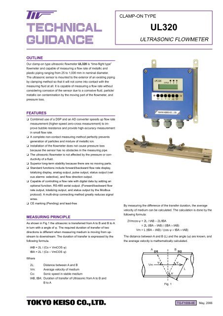
Our clamp-on type ultrasonic flowmeter UL320 is “time-flight type”<br />
flowmeter and capable of measuring a flow rate of metallic and<br />
plastic piping ranging from 25 to 1,000 mm in nominal diameter.<br />
The ultrasonic sensor is mounted to the exterior of an existing piping<br />
by clamping method so that it will not come into contact with the<br />
measuring fluid at all. It is capable of measuring a flow rate without<br />
considering corrosion of the sensor due to a corrosive fluid, particle/<br />
metallic ion contamination by the moving part of the flowmeter, and<br />
pressure loss.<br />
FEATURES<br />
❏ Combined use of a DSP and an AD converter speeds up flow rate<br />
measurement (higher-speed zero-cross measurement) to improve<br />
bubble resistance and provide high-accuracy measurement<br />
in small flow rate.<br />
❏ A complete non-contact measuring method perfectly prevents<br />
generation of particles and mixture of metallic ion.<br />
❏ Installation of the flowmeter does not cause pressure loss<br />
because the sensor has no obstacles in the measuring pipe.<br />
❏ The ultrasonic flowmeter is not affected by the pressure or conductivity<br />
of a fluid.<br />
❏ Superior long-term stability because there are no moving parts.<br />
❏ Standard functions include forward/backward flow rate display,<br />
totalizing display, analog output, pulse output, status output (vari<br />
ous alarms: selective), and flow direction output.<br />
❏ Capable of controlling a flow rate with digital data by adding an<br />
optional function, RS-485 serial output. (Forward/backward flow<br />
rate output, totalizing output, and status output by the Modbus<br />
protocol) A multi-drop connecting method greatly reduces signal<br />
wires.<br />
❏ CE marking (Pending) and lead-free<br />
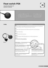
MEASURING PRINCIPLE<br />
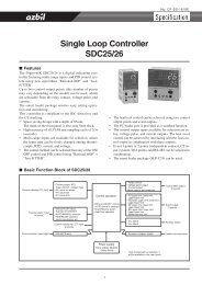
As shown in Fig.1 the ultrasonic is transferred from A to B and B to A<br />
in turn with a angle of ψ. The required duration of transfer of two<br />
directions is different when measuring medium is moving from upstream<br />
to downstream. The duration of transfer is expressed by the<br />
following formula.<br />
By measuring the difference of the transfer duration, the average<br />
velocity of medium can be calculated. The calculation is done by the<br />
following formula:<br />
2Vmcos ψ = 2L / tAB – 2L/tBA<br />
ψ = 2L (tBA – tAB) / (tBA × tAB)<br />
Vm = L (tBA – tAB) / (cos ψ × tBA × tAB)<br />
The distance between A and B (L) and the angle (ψ) are known, and<br />
the average velocity is mathematically calculated.<br />
tAB = 2L / (Co + VmCOS ψ)<br />
tBA = 2L / (Co – VmCOS ψ)<br />
A<br />
B<br />
Where<br />
2L: Distance between A and B<br />
Vm: Average velocity of medium<br />
Co: Sonic speed in stable medium<br />
tAB, tBA: Duration of transfer of Ultrasonic from A to B and<br />
B to A<br />
Vm<br />
ψ<br />
ψ<br />
Fig. 1<br />
ψ<br />
L<br />
TG-F1006-0E May, 2006
UL320 <strong>ULTRASONIC</strong> <strong>FLOWMETER</strong><br />
STANDARD SPECIFICATION<br />
● Measuring method : Ultrasonic time-flight type (Ultrasonic path<br />
Reflex mode/ V path or Diagonal mode/ Z<br />
path)<br />
● Construction : Sensor, Converter, Exclusive coaxial cable<br />
with BNC connector, and Sensor fixing rail)<br />
● Sensor mounting : Piping clamp-on type<br />
● Measuring fluid : Liquids which can be penetrated with ultrasonic<br />
waves (Not suitable for liquids containing<br />
many bubbles and slurry and high<br />
viscosity liquids).<br />
● Measurable fluid ultrasonic range (viscosity)<br />
: 1,000 to 2,500 m/s (0.30 to 40.00 mm 2 /s)<br />
● Fluid temperature : Up to 90ºC (Piping surface temperature)<br />
● Measurable piping materials<br />
: SGP, Stainless steel, PVC, PVDF, PP, and<br />
PE (Materials which can be penetrated with<br />
ultrasonic waves.)<br />
● Measurable nominal piping diameter<br />
: 25mm (Min.) to 1,000mm (Max.) (Rater to<br />
Table 1 for sensor selection and its mount<br />
ing method)<br />
● Measurable flow velocity range<br />
: 0.3 m/s (At minimum settable full scale<br />
flow rate)<br />
10 m/s (At maximum settable full scale<br />
flow rate)<br />
● Accuracy<br />
: At flow velocity of 1 m/s or more; Reynolds<br />
number Re = 10,000 or more, Indication<br />
value +/- 2.0%<br />
At flow velocity of less than 1 m/s; Flow<br />
velocity error = +/-2 cm/s<br />
● Display<br />
: 16-digit, 2-line alphanumeric LCD (with<br />
backlight) and status display LEDs (3<br />
pieces)<br />
Display data : Flow rate, totalizing flow rate, various<br />
status, forward and backward flow direc<br />
tions<br />
● Power supply : AC type;100 to 240 V AC, 50/60 Hz (Operating<br />
voltage range: 85 to 264 V AC, 50/60<br />
Hz),<br />
DC type; 24 V DC +/- 10%<br />
● Power consumption : AC type; 10 VA or less,<br />
DC type; 8 W or less<br />
● Cable entry : For power/output (M20 x 1.5, 3 pieces);<br />
With waterproof cable gland (Applicable<br />
cable diameter: ø8.0 to ø13.0)<br />
For sensor; Waterproof BNC connector (2<br />
pieces)<br />
● Outputs<br />
1) Analog output : 4 to 20 mA DC or 0 to 20 mA DC (Selec<br />
tive), Load resistance: 500Ω or less<br />
2) Pulse output : Open collector output: Load rating: 30 V DC,<br />
50mA<br />
Pulse width: 0.5 ms/1000PPS, 0.5ms/100PPS,<br />
50ms/ 10PPS, 500ms/1pps,<br />
1000ms 0.5PPS (Selective)<br />
3) Status output : Status 1/2: 2 kinds selectable out of Flow<br />
rate alarm H, Flow rate alarm L, Preset A,<br />
Preset B, and Error alarm<br />
Status 3: Flow direction (fixed)<br />
Common to Status 1 to 3: Open collector,<br />
Load resistance : 30 V DC, 50 mA,<br />
Operation mode : NO/NC (Selective)<br />
4) Serial output : RS-485 serial output (option), Modbus protocol<br />
Transmission speed/distance — 2,400, 4,800,<br />
9,600 or 19,200 PPS, 1.2 km (Max. total dist<br />
ance at the time of multi-drop connection)<br />
Slave addresses: 1 to 31, Hard (DIP) setting<br />
(optionally settable)<br />
* For details of a data format, consult our factory.<br />
● Damping setting : 0 to 100 s (Settable in increments of 1s step)<br />
*Valid for display, analog output and pulse output.<br />
There is a response delay of 0.1 s, even if damping is<br />
set to 0 s.<br />
● Low cutoff setting<br />
: 0 to 30% of the maximum flow rate<br />
(Settable in increments of 1%)<br />
* Valid for display, analog output and pulse output.<br />
● Parameter setting : Set with the key switches on the<br />
converter’s front panel.<br />
● Other additional functions<br />
1) Analog and pulse simulation output function (For loop check)<br />
2) Forward/backward direction measuring function<br />
● Painting of converter : Epoxy resin painting (Blue/Light gray)<br />
● Converter mounting method : Mounted onto the wall or 2B pipe<br />
● Enclosure<br />
: Converter / IP65 Jet-proof,<br />
Sensor / IP65 Jet-proof (BNC connector<br />
guaranteed in the coupled condition)<br />
● Material<br />
: Sensor housing / ABS<br />
Sensor mounting rail / Aluminum<br />
Converter housing / Aluminum alloy<br />
● Converter ambient temperature and humidity<br />
: -20 to 50ºC, 10 to 90% RH (No dew<br />
condensation)<br />
● Sensor signal cable : Standard 10 m (Up to 60 m)<br />
Table 1. Sensor choice table<br />
Nominal pipe<br />
Pipe material<br />
size (D)<br />
Resin<br />
(PVC • PE etc.)<br />
Resin<br />
(PVDF • PP etc.)<br />
Metal<br />
25AD50A<br />
65AD150A<br />
200AD450A<br />
500AD1000A<br />
25AD50A<br />
65AD150A<br />
200AD400A<br />
25AD150A<br />
200AD450A<br />
500AD1000A<br />
Sensor installation Sensor rail length Support rail<br />
V<br />
V<br />
V<br />
Z<br />
V<br />
V<br />
Z<br />
V<br />
V<br />
Z<br />
3201 pc<br />
3201 pc<br />
6201 pc<br />
6202 pcs<br />
3201 pc<br />
3201 pc<br />
3202 pcs<br />
3201 pc<br />
6201 pc<br />
6202 pcs<br />
3201 pc<br />
Not provided<br />
Not provided<br />
Not provided<br />
3201 pc<br />
Not provided<br />
Not provided<br />
Not provided<br />
Not provided<br />
Not provided<br />
Code of sensor<br />
combination<br />
1<br />
2<br />
3<br />
4<br />
1<br />
2<br />
5<br />
2<br />
3<br />
4<br />
Note 1.: For unspecified resin piping, consult our factory.<br />
Note 2.: Metallic piping materials are stainless steel. (For schedule 80 or above, consult our factory in advance)<br />
Note 3.: The sensor mounting method V path to the reflex mode and Z path to the Diagonal mode.<br />
Note 4.: If the installed piping nominal diameter is unknown (100mm or more) or if the mounting piping may be changed, select Sensor Rails Length<br />
“620 mm1 pc or 620 mm2 pcs” Type: Combination code.<br />
Note 5.: A reinforcement rail is used for the resin piping whose nominal diameter is 50mm or less.<br />
Note 6. Refer to MODEL CODE.<br />
2 TOKYO KEISO CO., LTD. TG-F1006-0E
25<br />
25<br />
25<br />
25<br />
50<br />
50<br />
75<br />
75 50<br />
75<br />
75 50<br />
10<br />
0<br />
10<br />
0<br />
15<br />
0<br />
15<br />
0<br />
25<br />
25<br />
50<br />
75<br />
75 50<br />
10<br />
0<br />
12<br />
5<br />
15<br />
0<br />
UL320 <strong>ULTRASONIC</strong> <strong>FLOWMETER</strong><br />
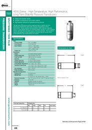
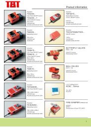
DIMENSIONS<br />
CONVERTER<br />
● Wall mount type<br />
● 2" pipe mount<br />
160<br />
140<br />
4-9<br />
90 15<br />
160<br />
(135)<br />
UFC320<br />
STATUS<br />
UFC320<br />
STATUS<br />
190<br />
(210)<br />
160<br />
MENU<br />
[ENT.]<br />
ZERO MEAS.<br />
[BACK] [SET]<br />
MENU<br />
[ENT.]<br />
ZERO MEAS.<br />
[BACK] [SET]<br />
TOKYO KEISO<br />
CO.,LTD.<br />
TOKYO KEISO<br />
CO.,LTD.<br />
(28)<br />
SENSOR<br />
● Reflex mode (V path: Nominal diameter D: 25A D 450A)<br />
● Diagonal mode (Z path: Nominal diameter D: 500A D)<br />
L<br />
(135)<br />
620 (205)<br />
15<br />
0<br />
10<br />
0<br />
38<br />
38<br />
15<br />
0<br />
12<br />
5<br />
10<br />
0<br />
Support rail *<br />
320<br />
(160)<br />
*Reflex mode (V path) Rail length<br />
Nominal pipe size: D (mm) L (mm)<br />
25A D 150A 320mm<br />
200A D 450A 620mm<br />
*Support rail is to be used for the resin pipe<br />
from 25 to 50mm.<br />
38<br />
15<br />
0<br />
10<br />
0<br />
FLOW RATE RANGE/SIZE<br />
Nominal diameter<br />
(mm)<br />
25<br />
32<br />
40<br />
50<br />
65<br />
80<br />
100<br />
125<br />
150<br />
200<br />
250<br />
300<br />
350<br />
400<br />
500<br />
600<br />
700<br />
800<br />
900<br />
1000<br />
TG-F1006-0E<br />
Possible scale range (m 3 /h)<br />
Minimum<br />
Maximum<br />
0.684<br />
22.80<br />
1.167<br />
38.91<br />
1.568<br />
52.27<br />
2.556<br />
85.21<br />
4.192<br />
139.7<br />
5.857<br />
195.2<br />
9.948<br />
331.6<br />
15.00<br />
500.1<br />
21.28<br />
709.4<br />
36.80<br />
1226<br />
57.07<br />
1902<br />
81.25<br />
2708<br />
101.3<br />
3377<br />
133.2<br />
4442<br />
209.5<br />
6984<br />
0.301(km 3 /h)<br />
10.06(km 3 /h)<br />
0.409(km 3 /h)<br />
13.66(km 3 /h)<br />
0.538(km 3 /h)<br />
17.95(km 3 /h)<br />
0.684(km 3 /h)<br />
22.82(km 3 /h)<br />
0.843(km 3 /h)<br />
28.10(km 3 /h)<br />
[Note] The above-mentioned flow rates have been calculated for the SUS Sch. 10s<br />
pipes, at the minimum range flow velocity of 0.3 m/s and maximum range<br />
flow velocity of 10 m/s.<br />
(The flow rate range may differ slightly, depending on the piping standard.)<br />
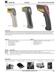
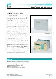
ELECTRICAL CONNECTION<br />
TB1(3P) TB2(10P) TB3(3P)<br />
Analog<br />
External Status output Serial output<br />
Power supply output Pulse<br />
(AC/DC) DC4 to<br />
totalization Status Status<br />
RS-485<br />
output<br />
com<br />
Status<br />
20mA<br />
reset 1 2<br />
3 (Option)<br />
(3P) (2P) (2P) (2P) (4P) (3P)<br />
L1<br />
(+)<br />
L2<br />
(-)<br />
G<br />
1<br />
+<br />
2<br />
-<br />
3<br />
+<br />
4<br />
-<br />
5<br />
+<br />
Note: The AC type does not have the polarities L1 and L2.<br />
Note: For Status 1 and 2, you may select two out of flow rate alarms H and L,<br />
presets A and B, and error alarm. Status 3 is for flow direction (fixed).<br />
6<br />
-<br />
7<br />
+<br />
8<br />
+<br />
9 0<br />
com +<br />
A<br />
+<br />
B<br />
-<br />
C<br />
SG<br />
TOKYO KEISO CO., LTD. 3
UL320 <strong>ULTRASONIC</strong> <strong>FLOWMETER</strong><br />
MODEL CODE<br />
Sensor<br />
UFS320<br />
Sensor combination<br />
Cable length<br />
Additional functions<br />
Converter<br />
Model code<br />
A<br />
1 Short sensor rail 1 pc, Support rail 1 pc<br />
2 Short sensor rail 1 pc<br />
3 Long sensor rail 1 pc<br />
4 Long sensor rail 2 pcs<br />
5 Short sensor rail 2 pcs<br />
1 10m (Standard)<br />
2 20m<br />
3 30m<br />
4 40m<br />
5 50m<br />
6 60m<br />
(Blank) NA<br />
/Z Provided<br />
Description<br />
Converter Model code<br />
UFC320 A<br />
Power supply<br />
Mounting<br />
Serial output<br />
Additional functions<br />
A<br />
Description<br />
100 to 240 V AC 50/60Hz<br />
- -<br />
1 Wall mount type<br />
2 2“ pipe mount type<br />
1 Standard<br />
2 Modbus specification (With serial output RS-485)<br />
(Blank) NA<br />
/Z Provided<br />
PRECAUTION FOR USE<br />
* To ensure accurate flow rate measurement, straight pipes are required in the upstream and downstream of the sensor mounting position.<br />
(Generally, 10D or more on the upstream side and 5D or more on the downstream side; D = nominal piping diameter), (For details, refer to<br />
the Instruction manual or JEMIS-032)<br />
* Mount the sensor to the piping which is always filled with liquid. When used for a liquid containing bubbles, mount it to the position where they<br />
do not stay in the piping.<br />
* Except a ball valve (reduced type excluded) or gate valve used in the fully closed condition, mount to the downstream side of the sensor.<br />
* When installing outdoors for use, it is recommended to attach a waterproof cover to the sensor in order to prevent deterioration of sensor<br />
grease.<br />
* Specification subject to change without notice<br />
Head Office : Shiba Toho Building, 1 – 7 – 24 Shibakoen, Minato-ku, Tokyo 105 – 8558<br />
Tel : 03 – 3431 – 1625 (KEY) ; Fax : 03 – 3433 – 4922<br />
e-mail : overseas.sales@tokyokeiso.co.jp ; URL : http://www.tokyokeiso.co.jp<br />
4 TG-F1006-0E